bulb YAMAHA VIKING 2014 Owners Manual
[x] Cancel search | Manufacturer: YAMAHA, Model Year: 2014, Model line: VIKING, Model: YAMAHA VIKING 2014Pages: 180, PDF Size: 3.78 MB
Page 9 of 180

Wheel removal .............................. 8-39
Tire replacement ........................... 8-40
Wheel installation .......................... 8-41
Battery ........................................... 8-41
Jump-starting ................................ 8-45
Fuse replacement ......................... 8-47
Replacing a headlight bulb ........... 8-49
Headlight beam adjustment .......... 8-52
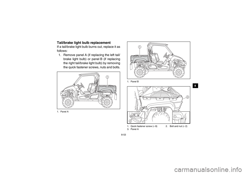
Tail/brake light bulb replacement ................................ 8-53
Troubleshooting ............................ 8-55
Troubleshooting charts ................. 8-56
CLEANING AND STORAGE............ 9-1 Cleaning .......................................... 9-1
Storage............................................ 9-2
SPECIFICATIONS.......................... 10-1
CONSUMER INFORMATION ........ 11-1 Identification number records ....... 11-1
910111XP7B_EE.book Page 4 Tuesday, February 4, 2014 3:40 PM
Page 159 of 180
8-49
1
2
3
4
5
6
78
9
10
11
12
13
14
4. Turn the key to “ ” (on) and turn on theelectrical circuit in question to check if the
device operates. If the fuse blows again
immediately, have a Yamaha dealer
check the electrical system.
5. Install the hood.
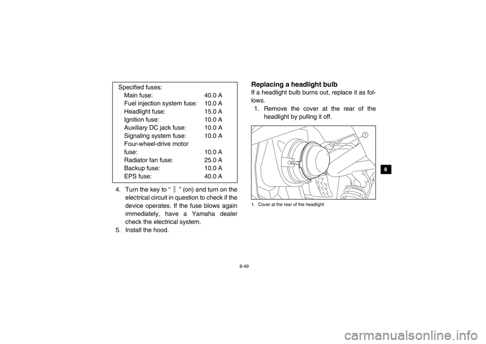
EVU01670Replacing a headlight bulbIf a headlight bulb burns out, replace it as fol-
lows. 1. Remove the cover at the rear of the headlight by pulling it off.1. Cover at the rear of the headlight
Specified fuses:Main fuse: 40.0 A
Fuel injection system fuse: 10.0 A
Headlight fuse: 15.0 A
Ignition fuse: 10.0 A
Auxiliary DC jack fuse: 10.0 A
Signaling system fuse: 10.0 A
Four-wheel-drive motor
fuse: 10.0 A
Radiator fan fuse: 25.0 A
Backup fuse: 10.0 A
EPS fuse: 40.0 A
1
1XP7B_EE.book Page 49 Tuesday, February 4, 2014 3:40 PM
Page 160 of 180
8-50
8
9
10
11
12
13
14
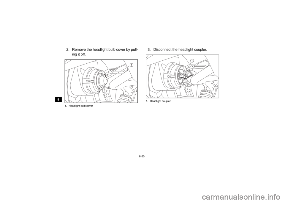
2. Remove the headlight bulb cover by pull- ing it off.1. Headlight bulb cover
3. Disconnect the headlight coupler.1. Headlight coupler
1
1
1XP7B_EE.book Page 50 Tuesday, February 4, 2014 3:40 PM
Page 161 of 180
8-51
1
2
3
4
5
6
78
9
10
11
12
13
14
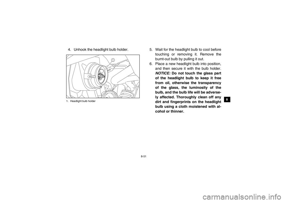
4. Unhook the headlight bulb holder.1. Headlight bulb holder
5. Wait for the headlight bulb to cool beforetouching or removing it. Remove the
burnt-out bulb by pulling it out.
6. Place a new headlight bulb into position, and then secure it with the bulb holder.
NOTICE: Do not touch the glass part
of the headlight bulb to keep it free
from oil, otherwise the transparency
of the glass, the luminosity of the
bulb, and the bulb life will be adverse-
ly affected. Thoroughly clean off any
dirt and fingerprints on the headlight
bulb using a cloth moistened with al-
cohol or thinner.
1
1XP7B_EE.book Page 51 Tuesday, February 4, 2014 3:40 PM
Page 162 of 180
8-52
8
9
10
11
12
13
14
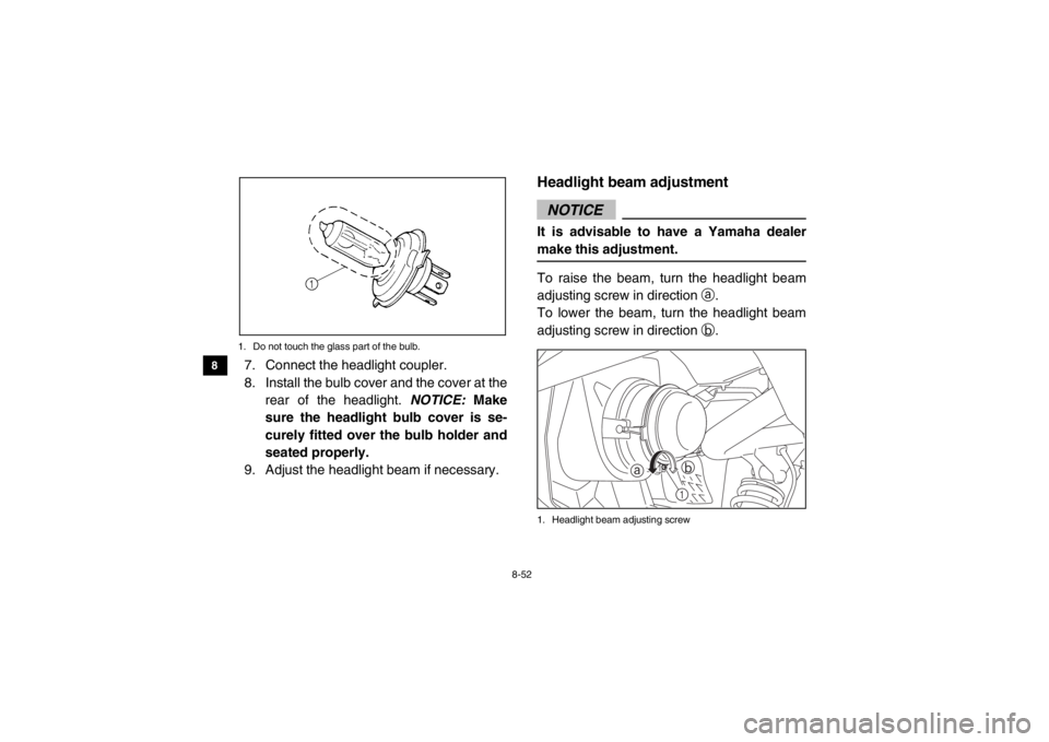
1. Do not touch the glass part of the bulb.7. Connect the headlight coupler.
8. Install the bulb cover and the cover at the rear of the headlight. NOTICE: Make
sure the headlight bulb cover is se-
curely fitted over the bulb holder and
seated properly.
9. Adjust the headlight beam if necessary.
EVU00990Headlight beam adjustmentNOTICEIt is advisable to have a Yamaha dealer
make this adjustment.To raise the beam, turn the headlight beam
adjusting screw in direction a.
To lower the beam, turn the headlight beam
adjusting screw in direction b.1. Headlight beam adjusting screw
1
a
b
1XP7B_EE.book Page 52 Tuesday, February 4, 2014 3:40 PM
Page 163 of 180
8-53
1
2
3
4
5
6
78
9
10
11
12
13
14
EVU01000Tail/brake light bulb replacementIf a tail/brake light bulb burns out, replace it as
follows:1. Remove panel A (if replacing the left tail/ brake light bulb) or panel B (if replacing
the right tail/brake light bulb) by removing
the quick fastener screws, nuts and bolts.1. Panel A 1. Panel B
1. Quick fastener screw (
× 8) 2. Bolt and nut ( × 2)
3. Panel A
1
1
1
3
2 1
1XP7B_EE.book Page 53 Tuesday, February 4, 2014 3:40 PM
Page 164 of 180
8-54
8
9
10
11
12
13
14
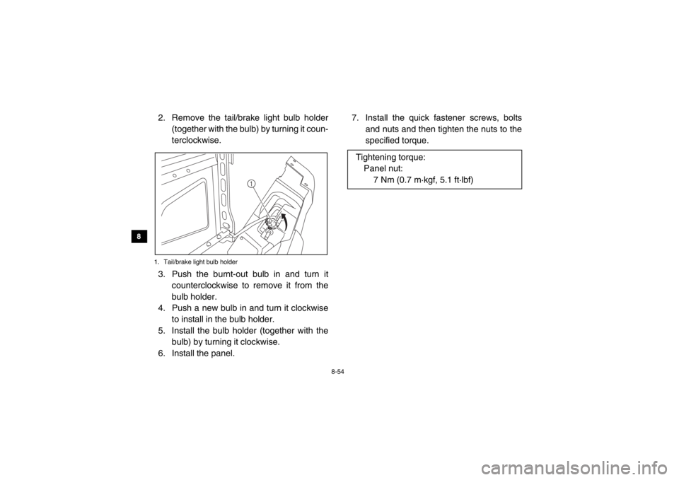
2. Remove the tail/brake light bulb holder (together with the bulb) by turning it coun-
terclockwise.1. Tail/brake light bulb holder3. Push the burnt-out bulb in and turn itcounterclockwise to remove it from the
bulb holder.
4. Push a new bulb in and turn it clockwise to install in the bulb holder.
5. Install the bulb holder (together with the bulb) by turning it clockwise.
6. Install the panel. 7. Install the quick fastener screws, bolts
and nuts and then tighten the nuts to the
specified torque.
1
Tightening torque:Panel nut: 7 Nm (0.7 m·kgf, 5.1 ft·lbf)
1XP7B_EE.book Page 54 Tuesday, February 4, 2014 3:40 PM
Page 174 of 180

10-4
10
11
12
13
14
Vehicle load: 300 kg – maximum (661 lb – maximum):
Front:70.0 kPa (0.700 kgf/cm
2, 10 psi)
Rear:
120.0 kPa (1.200 kgf/cm2, 17 psi)
Front wheel:Wheel type:Cast wheel
Rim size:
12 × 6.0ATRear wheel:Wheel type:
Cast wheel
Rim size:
12 × 7.5ATFront brake:Type:
Disc brake
Operation:
Unified brake
Recommended fluid: DOT 4Rear brake:Type:
Disc brake
Operation: Unified brake
Recommended fluid: DOT 4
Front suspension:Type:Double wishbone
Spring/shock absorber type:
Coil spring/gas-oil damper
Wheel travel: 205 mm (8.1 in)Rear suspension:Type:
Double wishbone
Spring/shock absorber type: Coil spring/gas-oil damper
Wheel travel: 205 mm (8.1 in)Electrical system:Ignition system:TCI
Charging system: AC magnetoBattery:Model:U1-H11L
Voltage, capacity: 12 V, 28.0 AhHeadlight:Bulb type:Halogen bulbBulb voltage, wattage
× quantity:
Headlight:
12 V, 35.0/35.0 W × 2
Tail/brake light: 12 V, 5.0/21.0 W × 2
1XP7B_EE.book Page 4 Tuesday, February 4, 2014 3:40 PM