check engine light YAMAHA VMAX 2001 Owners Manual
[x] Cancel search | Manufacturer: YAMAHA, Model Year: 2001, Model line: VMAX, Model: YAMAHA VMAX 2001Pages: 110, PDF Size: 11.88 MB
Page 17 of 110
INSTRUMENT AND CONTROL FUNCTIONS
3-2
3
EAU00083
Fuel level warning light “ ”
This warning light comes on when the
fuel level drops below approximately
3 L. When this occurs, set the fuel re-
serve switch to the “RES” position and
refuel as soon as possible.
EAU00063
High beam indicator light “ ”
This indicator light comes on when the
high beam of the headlight is switched
on.
EAU03285
Oil level warning light “ ”
This warning light comes on when the
engine oil level is low.
The electrical circuit of the warning light
can be checked according to the fol-
lowing procedure.
1. Turn the key to “ON”.
2. If the warning light does not come
on, have a Yamaha dealer check
the electrical circuit.NOTE:@ Even if the oil level is sufficient, the
warning light may flicker when riding on
a slope or during sudden acceleration
or deceleration, but this is not a mal-
function. @
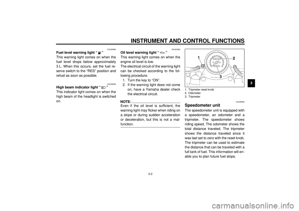
EAU00095
Speedometer unit The speedometer unit is equipped with
a speedometer, an odometer and a
tripmeter. The speedometer shows
riding speed. The odometer shows the
total distance traveled. The tripmeter
shows the distance traveled since it
was last set to zero with the reset knob.
The tripmeter can be used to estimate
the distance that can be traveled with a
full tank of fuel. This information will en-
able you to plan future fuel stops.1. Tripmeter reset knob
2. Odometer
3. Tripmeter
E_3lr.book Page 2 Wednesday, November 22, 2000 4:10 PM
Page 38 of 110
5-1
5
EAU00372
5-OPERATION AND IMPORTANT RIDING POINTS
EAU00373
WARNING
@ l
Become thoroughly familiar
with all operating controls and
their functions before riding.
Consult a Yamaha dealer re-
garding any control or function
that you do not thoroughly un-
derstand.
l
Never start the engine or oper-
ate it in a closed area for any
length of time. Exhaust fumes
are poisonous, and inhaling
them can cause loss of con-
sciousness and death within a
short time. Always make sure
that there is adequate ventila-
tion.
l
Before starting out, make sure
that the sidestand is up. If the
sidestand is not raised com-
pletely, it could contact the
ground and distract the opera-
tor, resulting in a possible loss
of control.
@
EAU01627
Starting a cold engine In order for the ignition circuit cut-off
system to enable starting, one of the
following conditions must be met:l
The transmission is in the neutral
position.
l
The transmission is in gear with
the clutch lever pulled and the
sidestand up.
EW000054
WARNING
@ l
Before starting the engine,
check the function of the igni-
tion circuit cut-off system ac-
cording to the procedure
described on page 3-16.
l
Never ride with the sidestand
down.
@1. Turn the key to “ON” and make
sure that the engine stop switch is
set to “ ”.
EC000035
CAUTION:@ If the fuel level warning light comes
on, check the fuel level, and, if nec-
essary, refuel as soon as possible. @2. Shift the transmission into the neu-
tral position.NOTE:@ When the transmission is in the neutral
position, the neutral indicator light
should be on, otherwise have a
Yamaha dealer check the electrical cir-
cuit. @3. Turn the starter (choke) on and
completely close the throttle. (See
page 3-8 for starter (choke) opera-
tion.)
4. Start the engine by pushing the
start switch.
E_3lr.book Page 1 Wednesday, November 22, 2000 4:10 PM
Page 39 of 110
OPERATION AND IMPORTANT RIDING POINTS
5-2
5
NOTE:@ If the engine fails to start, release the
start switch, wait a few seconds, and
then try again. Each starting attempt
should be as short as possible to pre-
serve the battery. Do not crank the en-
gine more than 10 seconds on any one
attempt. @
EC000038
CAUTION:@ l
The oil level warning light and
fuel level warning light should
come on when the start switch
is pushed, and they should go
off when the start switch is re-
leased.
l
If the oil level warning light flick-
ers or remains on after starting,
immediately stop the engine,
and then check the engine oil
level and the vehicle for oil leak-
age. If necessary, add engine
oil, and then check the warning
light again. If the warning light
does not come on when push-
ing the start switch, or if it doesnot go off after starting with suf-
ficient engine oil, have a
Yamaha dealer check the elec-
trical circuit.
l
If the fuel level warning light re-
mains on after starting, stop the
engine, and then check the fuel
level. If necessary, refuel as
soon as possible, and then
check the warning light again. If
the warning light does not come
on when pushing the start
switch, or if it does not go off af-
ter starting with sufficient fuel,
have a Yamaha dealer check the
electrical circuit.
@5. After starting the engine, move the
starter (choke) lever back halfway.
ECA00045
CAUTION:@ For maximum engine life, never ac-
celerate hard when the engine is
cold! @
6. When the engine is warm, turn the
starter (choke) off.NOTE:@ The engine is warm when it responds
normally to the throttle with the starter
(choke) turned off. @
E_3lr.book Page 2 Wednesday, November 22, 2000 4:10 PM
Page 43 of 110
6
PERIODIC MAINTENANCE AND MINOR REPAIR
Owner’s tool kit .................................................... 6-1
Periodic maintenance and lubrication chart ......... 6-3
Removing and installing cowlings and panels ..... 6-6
Checking the spark plugs .................................... 6-7
Engine oil and oil filter cartridge .......................... 6-9
Final gear oil ...................................................... 6-13
Coolant .............................................................. 6-14
Cleaning the air filter element ............................ 6-19
Adjusting the carburetors ................................... 6-20
Adjusting the engine idling speed ...................... 6-20
Adjusting the throttle cable free play .................. 6-21
Adjusting the valve clearance ............................ 6-21
Tires ................................................................... 6-21
Cast wheels ....................................................... 6-24
Clutch lever free play ......................................... 6-24
Adjusting the brake lever free play ..................... 6-25
Adjusting the brake pedal position ..................... 6-25
Adjusting the rear brake light switch .................. 6-26
Checking the front and rear brake pads ............. 6-26
Checking the brake fluid level ............................ 6-27
Changing the brake fluid .................................... 6-28
Checking and lubricating the cables .................. 6-28Checking and lubricating the throttle
grip and cable ................................................. 6-29
Checking and lubricating the brake and
shift pedals ...................................................... 6-29
Checking and lubricating the brake and
clutch levers .................................................... 6-30
Checking and lubricating the centerstand and
sidestand......................................................... 6-30
Lubricating the rear suspension ........................ 6-31
Checking the front fork ...................................... 6-31
Checking the steering ....................................... 6-32
Checking the wheel bearings ............................ 6-33
Battery ............................................................... 6-33
Replacing the fuses .......................................... 6-37
Replacing the headlight bulb ............................. 6-38
Replacing a turn signal light bulb or the tail/
brake light bulb ................................................ 6-39
Front wheel ....................................................... 6-40
Rear wheel ........................................................ 6-41
Troubleshooting ................................................. 6-44
Troubleshooting charts ...................................... 6-45
E_3lr.book Page 1 Wednesday, November 22, 2000 4:10 PM
Page 51 of 110

PERIODIC MAINTENANCE AND MINOR REPAIR
6-8
6 2. Remove the spark plug as shown,
with the spark plug wrench includ-
ed in the owner’s tool kit.
To check the spark plugs
1. Check that the porcelain insulator
around the center electrode on
each spark plug is a medium-to-
light tan (the ideal color when the
motorcycle is ridden normally).
2. Check that all spark plugs installed
in the engine have the same color.
NOTE:@ If any spark plug shows a distinctly dif-
ferent color, the engine could be defec-
tive. Do not attempt to diagnose such
problems yourself. Instead, have a
Yamaha dealer check the motorcycle. @3. Check each spark plug for elec-
trode erosion and excessive car-
bon or other deposits, and replace
it if necessary.
To install a spark plug
1. Measure the spark plug gap with a
wire thickness gauge and, if nec-
essary, adjust the gap to specifica-
tion.
2. Clean the surface of the spark
plug gasket and its mating sur-
face, and then wipe off any grime
from the spark plug threads.
3. Install the spark plug with the
spark plug wrench, and then tight-
en it to the specified torque.
1. Spark plug wrench
Specified spark plug:
DPR8EA-9/NGK or
X24EPR-U9/DENSO
a. Spark plug gapSpark plug gap:
0.8–0.9 mm
E_3lr.book Page 8 Wednesday, November 22, 2000 4:10 PM
Page 52 of 110
PERIODIC MAINTENANCE AND MINOR REPAIR
6-9
6
NOTE:@ If a torque wrench is not available when
installing a spark plug, a good estimate
of the correct torque is 1/4–1/2 turn
past finger tight. However, the spark
plug should be tightened to the speci-
fied torque as soon as possible. @4. Install the spark plug cap.
EAU02938
Engine oil and oil filter
cartridge The engine oil level should be checked
before each ride. In addition, the oil
must be changed and the oil filter car-
tridge replaced at the intervals speci-
fied in the periodic maintenance and
lubrication chart.
To check the engine oil level
1. Place the motorcycle on the cen-
terstand.NOTE:@ Make sure that the motorcycle is posi-
tioned straight up when checking the oil
level. A slight tilt to the side can result in
a false reading. @2. Start the engine, warm it up for
several minutes, and then turn it
off.3. Wait a few minutes until the oil set-
tles, and then check the oil level
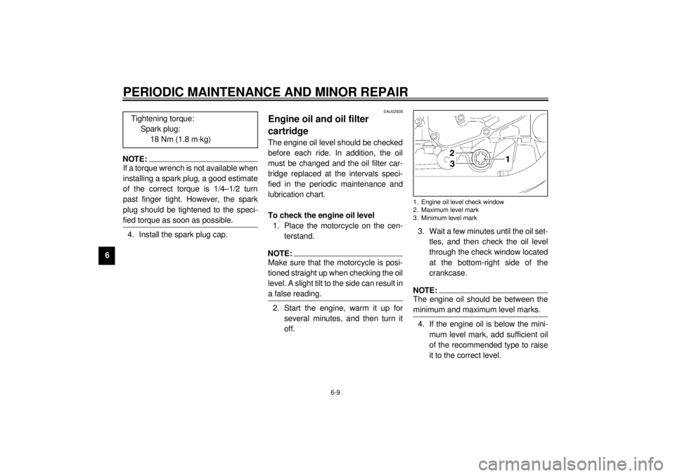
through the check window located
at the bottom-right side of the
crankcase.
NOTE:@ The engine oil should be between the
minimum and maximum level marks. @4. If the engine oil is below the mini-
mum level mark, add sufficient oil
of the recommended type to raise
it to the correct level. Tightening torque:
Spark plug:
18 Nm (1.8 m·kg)1. Engine oil level check window
2. Maximum level mark
3. Minimum level mark
E_3lr.book Page 9 Wednesday, November 22, 2000 4:10 PM
Page 55 of 110
PERIODIC MAINTENANCE AND MINOR REPAIR
6-12
6
EC000072
CAUTION:@ l
In order to prevent clutch slip-
page (since the engine oil also
lubricates the clutch), do not
mix any chemical additives with
the oil or use oils of a higher
grade than “CD”. In addition, do
not use oils labeled “ENERGY
CONSERVING II” or higher.
l
Make sure that no foreign mate-
rial enters the crankcase.
@9. Start the engine, and then let it idle
for several minutes while checking
it for oil leakage. If oil is leaking,
immediately turn the engine off
and check for the cause.NOTE:@ After the engine is started, the engine
oil level warning light should go off if the
oil level is sufficient. @
EC000067
CAUTION:@ If the oil level warning light flickers
or remains on, immediately turn the
engine off and have a Yamaha deal-
er check the vehicle. @10. Turn the engine off, and then
check the oil level and correct it if
necessary.
E_3lr.book Page 12 Wednesday, November 22, 2000 4:10 PM
Page 57 of 110
PERIODIC MAINTENANCE AND MINOR REPAIR
6-14
6
EAU03416
Coolant The coolant level should be checked
before each ride. In addition, the cool-
ant must be changed at the intervals
specified in the periodic maintenance
and lubrication chart.
If the engine overheats, see page 6-46
for further instructions.
To check the coolant level
1. Place the motorcycle on a level
surface and hold it in an upright
position.
2. Remove cowling A. (See page 6-6
for cowling removal and installa-
tion procedures.)
NOTE:@ l
The coolant level must be checked
on a cold engine since the level
varies with engine temperature.
l
Make sure that the motorcycle is
positioned straight up when
checking the coolant level. A slight
tilt to the side can result in a false
reading.
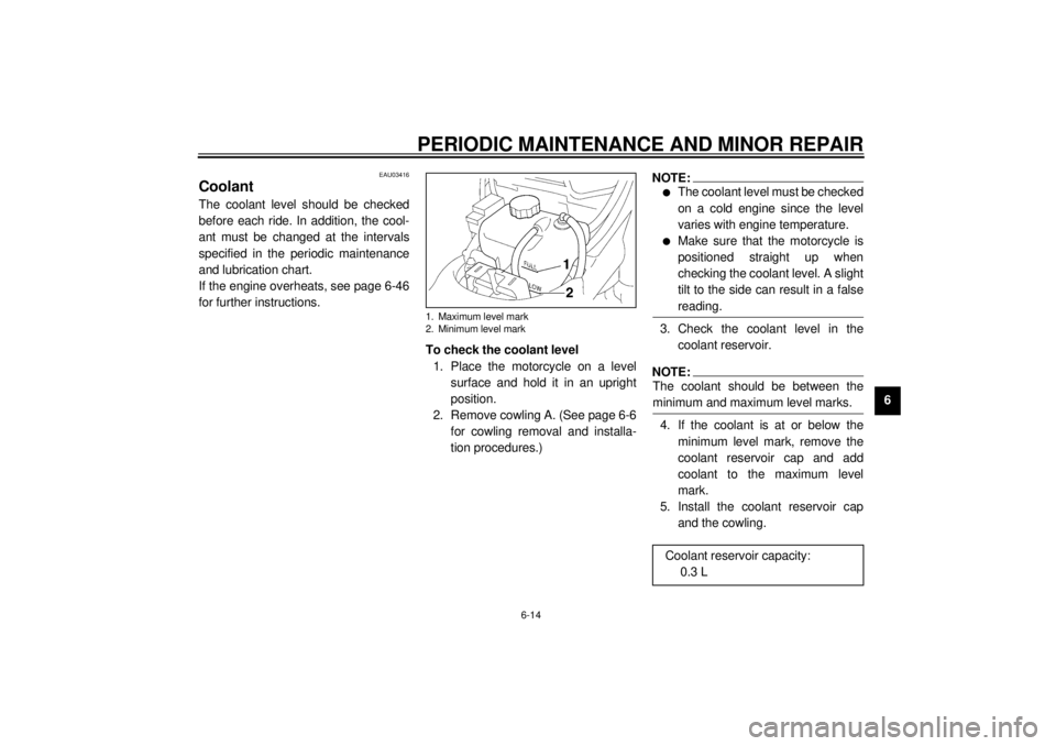
@3. Check the coolant level in the
coolant reservoir.NOTE:@ The coolant should be between the
minimum and maximum level marks. @4. If the coolant is at or below the
minimum level mark, remove the
coolant reservoir cap and add
coolant to the maximum level
mark.
5. Install the coolant reservoir cap
and the cowling.
1. Maximum level mark
2. Minimum level mark
Coolant reservoir capacity:
0.3 L
E_3lr.book Page 14 Wednesday, November 22, 2000 4:10 PM
Page 79 of 110
PERIODIC MAINTENANCE AND MINOR REPAIR
6-36
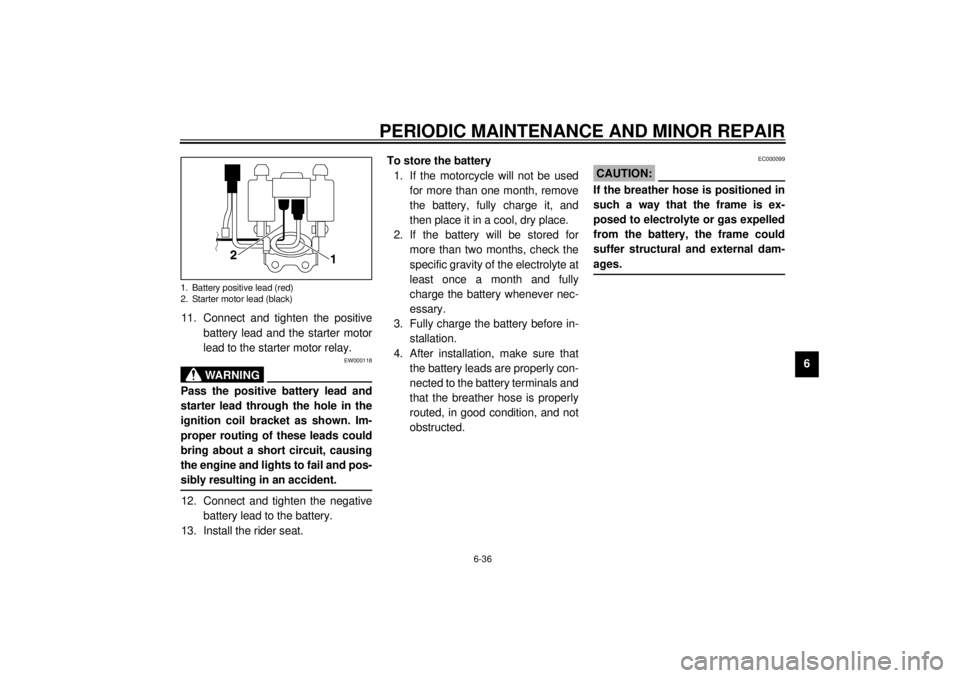
6 11. Connect and tighten the positive
battery lead and the starter motor
lead to the starter motor relay.
EW000118
WARNING
@ Pass the positive battery lead and
starter lead through the hole in the
ignition coil bracket as shown. Im-
proper routing of these leads could
bring about a short circuit, causing
the engine and lights to fail and pos-
sibly resulting in an accident. @12. Connect and tighten the negative
battery lead to the battery.
13. Install the rider seat.To store the battery
1. If the motorcycle will not be used
for more than one month, remove
the battery, fully charge it, and
then place it in a cool, dry place.
2. If the battery will be stored for
more than two months, check the
specific gravity of the electrolyte at
least once a month and fully
charge the battery whenever nec-
essary.
3. Fully charge the battery before in-
stallation.
4. After installation, make sure that
the battery leads are properly con-
nected to the battery terminals and
that the breather hose is properly
routed, in good condition, and not
obstructed.
EC000099
CAUTION:@ If the breather hose is positioned in
such a way that the frame is ex-
posed to electrolyte or gas expelled
from the battery, the frame could
suffer structural and external dam-
ages. @
1. Battery positive lead (red)
2. Starter motor lead (black)
E_3lr.book Page 36 Wednesday, November 22, 2000 4:10 PM
Page 106 of 110
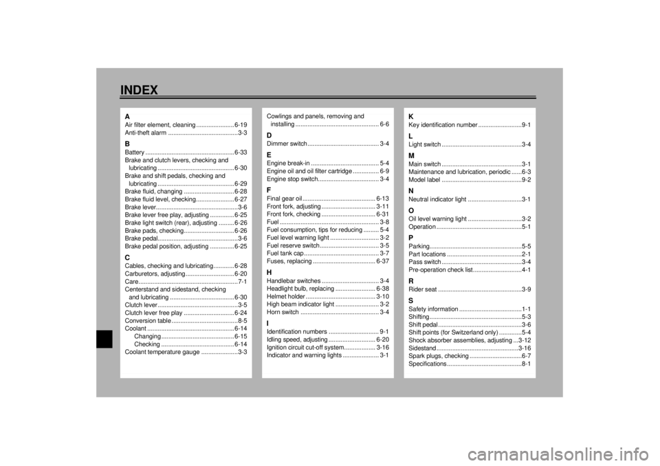
10-INDEXAAir filter element, cleaning ...................... 6-19
Anti-theft alarm ........................................3-3BBattery ................................................... 6-33
Brake and clutch levers, checking and
lubricating ............................................ 6-30
Brake and shift pedals, checking and
lubricating ............................................ 6-29
Brake fluid, changing ............................. 6-28
Brake fluid level, checking...................... 6-27
Brake lever...............................................3-6
Brake lever free play, adjusting .............. 6-25
Brake light switch (rear), adjusting ......... 6-26
Brake pads, checking............................. 6-26
Brake pedal..............................................3-6
Brake pedal position, adjusting .............. 6-25CCables, checking and lubricating............ 6-28
Carburetors, adjusting............................ 6-20
Care.........................................................7-1
Centerstand and sidestand, checking
and lubricating ..................................... 6-30
Clutch lever ..............................................3-5
Clutch lever free play ............................. 6-24
Conversion table ......................................8-5
Coolant .................................................. 6-14
Changing .......................................... 6-15
Checking .......................................... 6-14
Coolant temperature gauge .....................3-3
Cowlings and panels, removing and
installing................................................ 6-6DDimmer switch ......................................... 3-4EEngine break-in ....................................... 5-4
Engine oil and oil filter cartridge ............... 6-9
Engine stop switch................................... 3-4FFinal gear oil .......................................... 6-13
Front fork, adjusting ............................... 3-11
Front fork, checking ............................... 6-31
Fuel ......................................................... 3-8
Fuel consumption, tips for reducing ......... 5-4
Fuel level warning light ............................ 3-2
Fuel reserve switch.................................. 3-5
Fuel tank cap ........................................... 3-7
Fuses, replacing .................................... 6-37HHandlebar switches ................................. 3-4
Headlight bulb, replacing ....................... 6-38
Helmet holder ........................................ 3-10
High beam indicator light ......................... 3-2
Horn switch ............................................. 3-4IIdentification numbers ............................. 9-1
Idling speed, adjusting ........................... 6-20
Ignition circuit cut-off system.................. 3-16
Indicator and warning lights ..................... 3-1
KKey identification number .........................9-1LLight switch ..............................................3-4MMain switch ..............................................3-1
Maintenance and lubrication, periodic ......6-3
Model label ..............................................9-2NNeutral indicator light ...............................3-1OOil level warning light ...............................3-2
Operation .................................................5-1PParking.....................................................5-5
Part locations ...........................................2-1
Pass switch ..............................................3-4
Pre-operation check list ............................4-1RRider seat ................................................3-9SSafety information ....................................1-1
Shifting .....................................................5-3
Shift pedal ................................................3-6
Shift points (for Switzerland only) .............5-4
Shock absorber assemblies, adjusting ...3-12
Sidestand ...............................................3-16
Spark plugs, checking ..............................6-7
Specifications ...........................................8-1
E_3lr.book Page 1 Wednesday, November 22, 2000 4:10 PM