brake light YAMAHA VMAX 2012 Owners Manual
[x] Cancel search | Manufacturer: YAMAHA, Model Year: 2012, Model line: VMAX, Model: YAMAHA VMAX 2012Pages: 110, PDF Size: 3.09 MB
Page 6 of 110

TABLE OF CONTENTSSAFETY INFORMATION ..................1-1
DESCRIPTION ..................................2-1
Left view ..........................................2-1
Right view ........................................2-2
Controls and instruments.................2-3
INSTRUMENT AND CONTROL
FUNCTIONS .......................................3-1
Immobilizer system .........................3-1
Main switch/steering lock ................3-2
Indicator lights and warning lights ..............................3-4
Speedometer unit ...........................3-7
Multi-function display ......................3-8
Anti-theft alarm (optional) .............3-17
Handlebar switches ......................3-18
Clutch lever ...................................3-19
Shift pedal .....................................3-20
Brake lever ...................................3-20
Brake pedal ..................................3-21
ABS ..............................................3-21
Fuel tank cap ................................3-22
Fuel ...............................................3-23
Fuel tank breather hose and overflow hose ............................3-24
Catalytic converters ......................3-25
Seats ............................................3-25
Adjusting the front fork ..................3-27
Adjusting the shock absorber assembly ...................................3-29 Luggage strap holders ................. 3-31
EXUP system ............................... 3-31
Sidestand ..................................... 3-31
Ignition circuit cut-off system ........ 3-32
FOR YOUR SAFETY –
PRE-OPERATION CHECKS ............. 4-1
OPERATION AND IMPORTANT
RIDING POINTS ................................. 5-1
Starting the engine ......................... 5-1
Shifting ........................................... 5-2
Tips for reducing fuel consumption ............................... 5-3
Engine break-in .............................. 5-3
Parking ........................................... 5-4
PERIODIC MAINTENANCE AND
ADJUSTMENT ................................... 6-1
Owner’s tool kit ............................... 6-2
Periodic maintenance chart for
the emission control system ....... 6-3
General maintenance and
lubrication chart .......................... 6-4
Removing and installing the cowling and panels ............... 6-8
Checking the spark plugs ............. 6-10
Engine oil and oil filter cartridge ... 6-11
Final gear oil ................................. 6-14
Coolant ......................................... 6-16
Air filter element ........................... 6-19 Checking the engine idling
speed ........................................ 6-19
Checking the throttle grip free play ........................................... 6-20
Valve clearance ........................... 6-20
Tires ............................................. 6-20
Cast wheels ................................. 6-23
Clutch lever .................................. 6-23
Checking the brake lever free
play ........................................... 6-23
Brake light switches ..................... 6-24
Checking the front and
rear brake pads ........................ 6-24
Checking the brake fluid level ...... 6-25
Changing the brake and
clutch fluids ............................... 6-26
Checking and lubricating
the cables ................................. 6-27
Checking and lubricating the throttle grip and cable ......... 6-27
Checking and lubricating the brake and shift pedals ........ 6-27
Checking and lubricating
the brake and clutch levers ...... 6-28
Checking and lubricating the sidestand ............................ 6-29
Lubricating the swingarm pivots ........................................ 6-29
Checking the front fork ................. 6-29
Checking the steering .................. 6-30
Checking the wheel bearings ....... 6-30U2S3E3E0.book Page 1 Monday, September 19, 2011 8:42 AM
Page 7 of 110

TABLE OF CONTENTS
Battery .......................................... 6-31
Replacing the fuses ...................... 6-33
Replacing the headlight bulb ........ 6-35
Tail/brake light .............................. 6-36
Replacing a turn signal light bulb ........................................... 6-37
Replacing a license plate light bulb ........................................... 6-37
Replacing the auxiliary light bulb ........................................... 6-39
Supporting the motorcycle ............ 6-39
Troubleshooting ............................ 6-40
Troubleshooting charts ................. 6-41
MOTORCYCLE CARE AND
STORAGE .......................................... 7-1
Matte color caution ......................... 7-1
Care ................................................ 7-1
Storage ...........................................7-4
SPECIFICATIONS ............................. 8-1
CONSUMER INFORMATION ............. 9-1
Identification numbers .................... 9-1
U2S3E3E0.book Page 2 Monday, September 19, 2011 8:42 AM
Page 15 of 110
DESCRIPTION
2-3
2
EAU10430
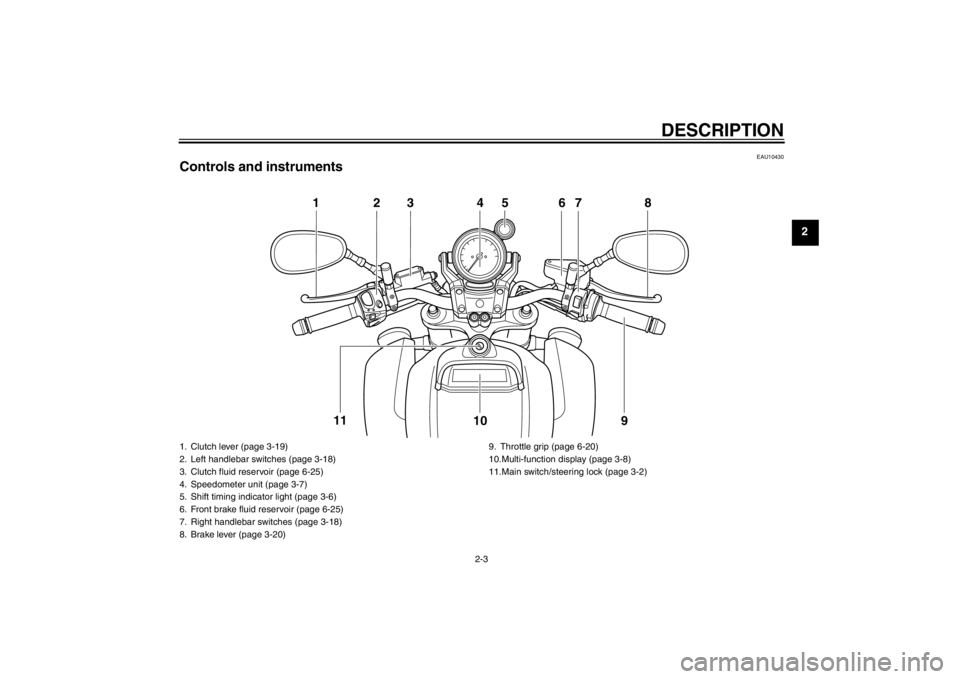
Controls and instruments
123 4 67 89
10
11
5
1. Clutch lever (page 3-19)
2. Left handlebar switches (page 3-18)
3. Clutch fluid reservoir (page 6-25)
4. Speedometer unit (page 3-7)
5. Shift timing indicator light (page 3-6)
6. Front brake fluid reservoir (page 6-25)
7. Right handlebar switches (page 3-18)
8. Brake lever (page 3-20) 9. Throttle grip (page 6-20)
10.Multi-function display (page 3-8)
11.Main switch/steering lock (page 3-2)
U2S3E3E0.book Page 3 Monday, September 19, 2011 8:42 AM
Page 19 of 110
INSTRUMENT AND CONTROL FUNCTIONS
3-4
3
EAU49391
Indicator lights and warning
lights
EAU11030
Turn signal indicator lights “ ”
and “ ”
The corresponding indicator light flash-
es when the turn signal switch is
pushed to the left or right.
EAU11060
Neutral indicator light “ ”
This indicator light comes on when the
transmission is in the neutral position.
EAU11080
High beam indicator light “ ”
This indicator light comes on when the
high beam of the headlight is switched
on.
EAU46565
Oil level warning light “ ”
This warning light comes on if the en-
gine oil level is low.
To check the electrical circuit of the
warning light, place the vehicle on a
level surface, set the engine stop
switch to “ ” and turn the key from
“OFF” to “ON”.
If the warning light does not come on
for a few seconds and then go off, have
a Yamaha dealer check the electrical
circuit.If the warning light stays on, proceed as
follows.
1. Set the engine stop switch to “ ”.
2. Turn the key to “OFF”, wait two minutes, and then turn the key to
“ON”.
3. If the warning light comes on and does not go off, check the engine
oil level. (See page 6-11.) If the
warning light still stays on after
confirming the oil level is correct,
have a Yamaha dealer check the
vehicle.
TIP●
This warning light will not come
on: when the engine is idling
when riding
if the engine has stalled and the key has not been turned from
“ON” to “OFF” and then back to
“ON”
However , if the warning light is on
when the engine is started, it will
stay on until the key is turned to
“OFF”.
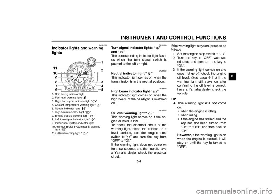
1. Shift timing indicator light
2. Fuel level warning light “ ”
3. Right turn signal indicator light “ ”
4. Coolant temperature warning light “ ”
5. Neutral indicator light “ ”
6. High beam indicator light “ ”
7. Engine trouble warning light “ ”
8. Left turn signal indicator light “ ”
9. Immobilizer system indicator light
10.Anti-lock Brake System (ABS) warning light “ ”
11.Oil level warning light “ ”11
10 2
1
9
3
4
5
8
7
6
ABS
U2S3E3E0.book Page 4 Monday, September 19, 2011 8:42 AM
Page 21 of 110
INSTRUMENT AND CONTROL FUNCTIONS
3-6
3
If the warning light does not come on
initially when the key is turned to “ON”,
or if the warning light remains on, have
a Yamaha dealer check the electrical
circuit.
EAU51661
ABS warning light “ ”
In normal operation, the ABS warning
light comes on when the key is turned
to “ON”, and goes off after traveling at a
speed of 10 km/h (6 mi/h) or higher.
If the ABS warning light:●
does not come on when the key is
turned to “ON”
●
comes on or flashes while riding
●
does not go off after traveling at a
speed of 10 km/h (6 mi/h) or higher
The ABS may not work correctly. If any
of the above occurs, have a Yamaha
dealer check the system as soon as
possible. (See page 3-21 for an expla-
nation of the ABS.)WARNING
EWA16040
If the ABS warning light does not go
off after traveling at a speed of 10
km/h (6 mi/h) or higher, or if the
warning light comes on or flashes while riding, the brake system re-
verts to conventional braking. If ei-
ther of the above occurs, or if the
warning light does not come on at
all, use extra caution to avoid possi-
ble wheel lock during emergency
braking. Have a Yamaha dealer
check the brake system and electri-
cal circuits as soon as possible.
TIPIf the start switch is pushed while the
engine is running, the ABS warning
light will come on, but this is not a mal-
function.
EAU48520
Shift timing indicator light
This indicator light can be set to come
on and go off at the desired engine
speeds and is used to inform the rider
when it is time to shift to the next higher
gear.
The electrical circuit of the indicator
light can be checked by turning the key
to “ON”. The indicator light should
come on for a few seconds, and then
go off.
If the indicator light does not come on
initially when the key is turned to “ON”,
or if the indicator light remains on, have
a Yamaha dealer check the electrical
circuit. (See page 3-10 for a detailed
explanation of the function of this indi-
cator light and on how to set it.)
EAU38624
Immobilizer system indicator light
The electrical circuit of the indicator
light can be checked by turning the key
to “ON”. The indicator light should
come on for a few seconds, and then
go off.
If the indicator light does not come on
initially when the key is turned to “ON”,
or if the indicator light remains on, have
a Yamaha dealer check the electrical
circuit.
When the key is turned to “OFF” and 30
seconds have passed, the indicator
light will start flashing indicating the im-
mobilizer system is enabled. After 24
hours have passed, the indicator light
will stop flashing, however the immobi-
lizer system is still enabled.
ABS
U2S3E3E0.book Page 6 Monday, September 19, 2011 8:42 AM
Page 36 of 110
INSTRUMENT AND CONTROL FUNCTIONS
3-21
3
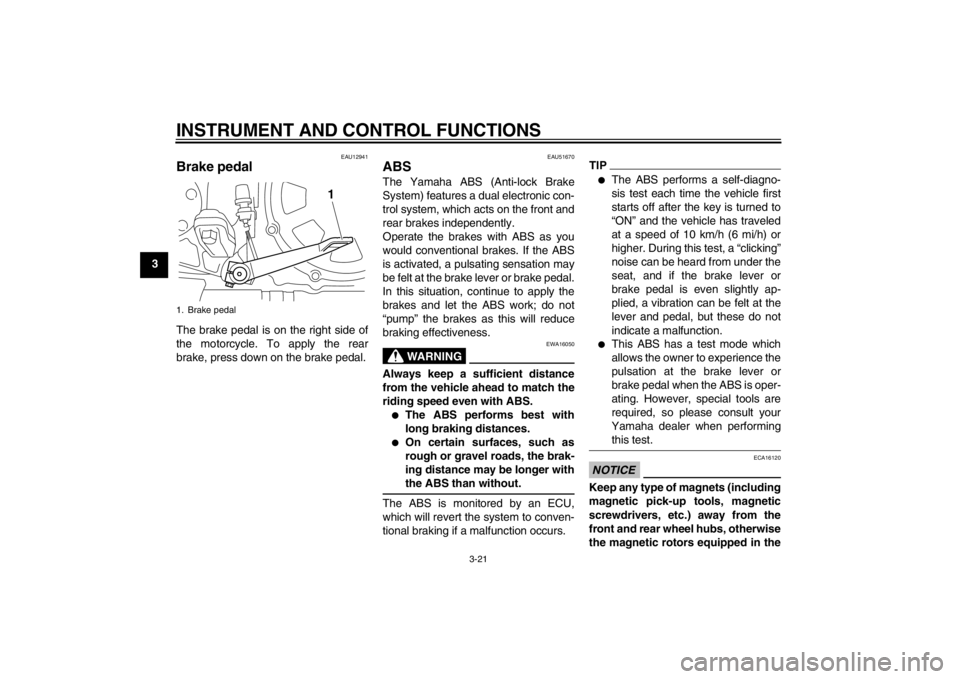
EAU12941
Brake pedal The brake pedal is on the right side of
the motorcycle. To apply the rear
brake, press down on the brake pedal.
EAU51670
ABS The Yamaha ABS (Anti-lock Brake
System) features a dual electronic con-
trol system, which acts on the front and
rear brakes independently.
Operate the brakes with ABS as you
would conventional brakes. If the ABS
is activated, a pulsating sensation may
be felt at the brake lever or brake pedal.
In this situation, continue to apply the
brakes and let the ABS work; do not
“pump” the brakes as this will reduce
braking effectiveness.
WARNING
EWA16050
Always keep a sufficient distance
from the vehicle ahead to match the
riding speed even with ABS.●
The ABS performs best with
long braking distances.
●
On certain surfaces, such as
rough or gravel roads, the brak-
ing distance may be longer with
the ABS than without.
The ABS is monitored by an ECU,
which will revert the system to conven-
tional braking if a malfunction occurs.
TIP●
The ABS performs a self-diagno-
sis test each time the vehicle first
starts off after the key is turned to
“ON” and the vehicle has traveled
at a speed of 10 km/h (6 mi/h) or
higher. During this test, a “clicking”
noise can be heard from under the
seat, and if the brake lever or
brake pedal is even slightly ap-
plied, a vibration can be felt at the
lever and pedal, but these do not
indicate a malfunction.
●
This ABS has a test mode which
allows the owner to experience the
pulsation at the brake lever or
brake pedal when the ABS is oper-
ating. However, special tools are
required, so please consult your
Yamaha dealer when performing
this test.
NOTICE
ECA16120
Keep any type of magnets (including
magnetic pick-up tools, magnetic
screwdrivers, etc.) away from the
front and rear wheel hubs, otherwise
the magnetic rotors equipped in the
1. Brake pedal
1
U2S3E3E0.book Page 21 Monday, September 19, 2011 8:42 AM
Page 50 of 110

FOR YOUR SAFETY – PRE-OPERATION CHECKS
4-2
4
Rear brake Check operation.
If soft or spongy, have Yamaha dealer bleed hydraulic system.
Check brake pads for wear.
Replace if necessary.
Check fluid level in reservoir.
If necessary, add specified brake fluid to specified level.
Check hydraulic system for leakage. 6-24, 6-25
Clutch Check operation.
If soft or spongy, have Yamaha dealer bleed hydraulic system.
Check hydraulic system for leakage. 6-23
Throttle grip Make sure that operation is smooth.
Check throttle grip free play.
If necessary, have Yamaha dealer adjust throttle grip free play and lubricate cable
and grip housing. 6-20, 6-27
Control cables Make sure that operation is smooth.
Lubricate if necessary. 6-27
Wheels and tires Check for damage.
Check tire condition and tread depth.
Check air pressure.
Correct if necessary.
6-20, 6-23
Brake and shift pedals Make sure that operation is smooth.
Lubricate pedal pivoting points if necessary.
6-27
Brake and clutch levers Make sure that operation is smooth.
Lubricate lever pivoting points if necessary. 6-28
Sidestand Make sure that operation is smooth.
Lubricate pivot if necessary.
6-29
Chassis fasteners Make sure that all nuts, bolts and screws are properly tightened.
Tighten if necessary.
—
Instruments, lights, signals
and switches Check operation.
Correct if necessary.
—
ITEM CHECKS PAGE
U2S3E3E0.book Page 2 Monday, September 19, 2011 8:42 AM
Page 62 of 110
PERIODIC MAINTENANCE AND ADJUSTMENT
6-7
6
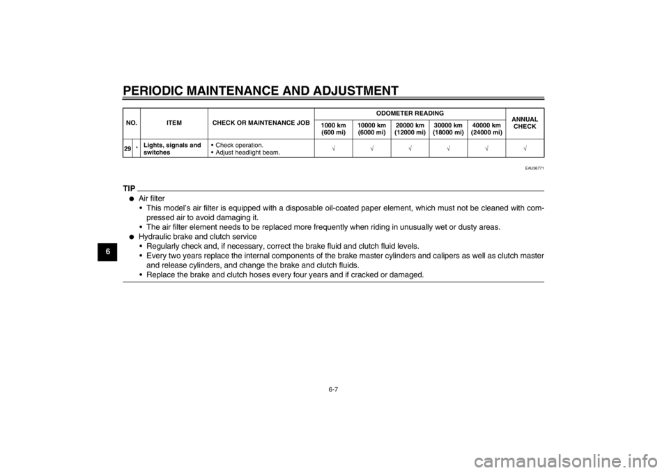
EAU36771
TIP●
Air filter This model’s air filter is equipped with a disposable oil-coated paper element, which must not be cleaned with com- pressed air to avoid damaging it.
The air filter element needs to be replaced more frequently when riding in unusually wet or dusty areas.
●
Hydraulic brake and clutch service Regularly check and, if necessary, correct the brake fluid and clutch fluid levels.
Every two years replace the internal components of the brake master cylinders and calipers as well as clutch master and release cylinders, and change the brake and clutch fluids.
Replace the brake and clutch hoses every four years and if cracked or damaged.
29 *Lights, signals and
switches Check operation.
Adjust headlight beam.
√√√√√√
NO. ITEM CHECK OR MAINTENANCE JOB
ODOMETER READING
ANNUAL
CHECK
1000 km
(600 mi) 10000 km
(6000 mi) 20000 km
(12000 mi) 30000 km
(18000 mi) 40000 km
(24000 mi)U2S3E3E0.book Page 7 Monday, September 19, 2011 8:42 AM
Page 79 of 110

PERIODIC MAINTENANCE AND ADJUSTMENT
6-24
6
braking performance, which may re-
sult in loss of control and an acci-
dent.
EAU36503
Brake light switches The brake light, which is activated by
the brake pedal and brake lever, should
come on just before braking takes ef-
fect. If necessary, have a Yamaha deal-
er adjust the brake light switches.
EAU22392
Checking the front and rear
brake pads The front and rear brake pads must be
checked for wear at the intervals spec-
ified in the periodic maintenance and
lubrication chart.
EAU43062
Front brake pads
The front brake calipers are equipped
with two sets of brake pads.
Each front brake pad is provided with
one or two wear indicator grooves,
which allow you to check the brake pad
wear without having to disassemble the
brake. To check the brake pad wear,
check the wear indicator grooves. If a
brake pad has worn to the point that a1. Brake pad wear indicator groove
1
1
U2S3E3E0.book Page 24 Monday, September 19, 2011 8:42 AM
Page 91 of 110

PERIODIC MAINTENANCE AND ADJUSTMENT
6-36
6
3. Unhook the headlight bulb holder,
and then remove the burnt-out
bulb.
4. Place a new headlight bulb into po- sition, and then secure it with the
bulb holder. 5. Install the headlight bulb cover,
and then connect the coupler.
6. Install the headlight unit by install- ing the bolts.
7. Have a Yamaha dealer adjust the headlight beam if necessary.
EAU24181
Tail/brake light This model is equipped with an LED-
type tail/brake light.
If the tail/brake light does not come on,
have a Yamaha dealer check it.
1. Headlight coupler
2. Headlight bulb cover
1. Headlight bulb holder
1
2
1
U2S3E3E0.book Page 36 Monday, September 19, 2011 8:42 AM