check engine YAMAHA VMAX 2015 User Guide
[x] Cancel search | Manufacturer: YAMAHA, Model Year: 2015, Model line: VMAX, Model: YAMAHA VMAX 2015Pages: 112, PDF Size: 3.16 MB
Page 31 of 112
INSTRUMENT AND CONTROL FUNCTIONS
3-16
3
Pushing “RESET” displays the
Normal mode for five seconds.
Pushing “SELECT” and “RESET”
for at least three seconds, chang-
es the display to the Normal
mode.
To perform further multi-function
display settings, enter the Select
mode again by pushing and hold-
ing “SELECT” and “RESET” for at
least three seconds.
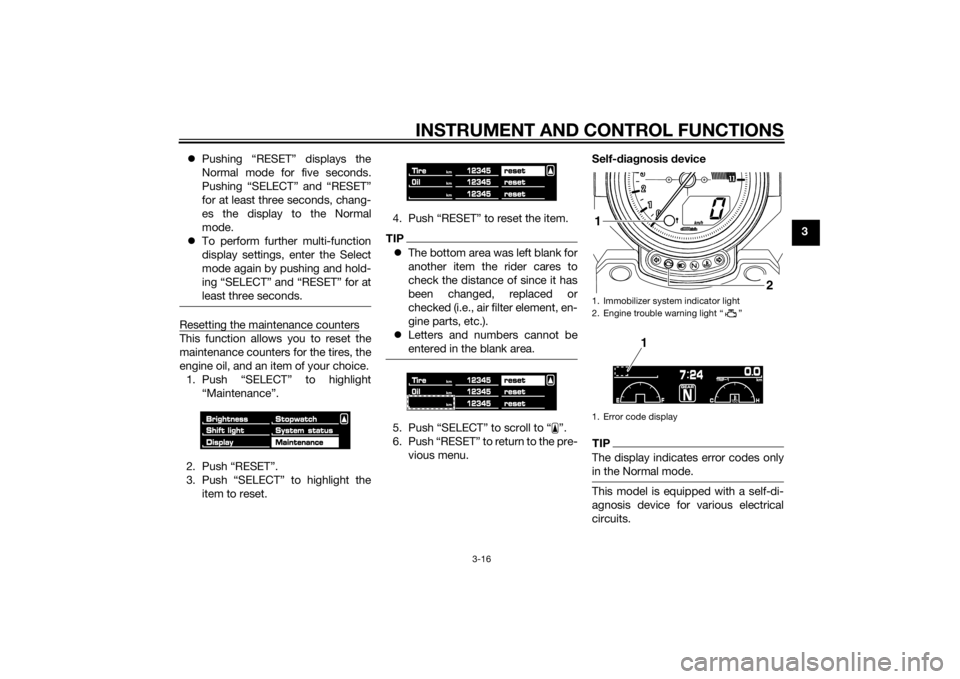
Resetting the maintenance countersThis function allows you to reset the
maintenance counters for the tires, the
engine oil, and an item of your choice.
1. Push “SELECT” to highlight “Maintenance”.
2. Push “RESET”.
3. Push “SELECT” to highlight the item to reset. 4. Push “RESET” to reset the item.
TIP
The bottom area was left blank for
another item the rider cares to
check the distance of since it has
been changed, replaced or
checked (i.e., air filter element, en-
gine parts, etc.).
Letters and numbers cannot be
entered in the blank area.5. Push “SELECT” to scroll to “ ”.
6. Push “RESET” to return to the pre-
vious menu. Self-d
iagnosis device
TIPThe display indicates error codes only
in the Normal mode.This model is equipped with a self-di-
agnosis device for various electrical
circuits.1. Immobilizer system indicator light
2. Engine trouble warning light “ ”
1. Error code display
2
1
1
U2CEE0E0.book Page 16 Wednesday, August 27, 2014 11:11 AM
Page 32 of 112
INSTRUMENT AND CONTROL FUNCTIONS
3-17
3If a problem is detected in any of those
circuits, the engine trouble warning
light comes on and the display indi-
cates an error code.
If the display indicates any error codes,
note the code number, and then have
a Yamaha dealer check the vehicle.
The self-diagnosis device also detects
problems in the immobilizer system
circuits.
If a problem is detected in any of the
immobilizer system circuits, the immo-
bilizer system indicator light flashes
and the display indicates an error
code.
TIPIf the display indicates error code 52,
this could be caused by transponder
interference. If this error code appears,
try the following.1. Use the code re-registering key to
start the engine.TIPMake sure there are no other immobi-
lizer keys close to the main switch, and
do not keep more than one immobilizer
key on the same key ring! Immobilizer system keys may cause signal interfer-
ence, which may prevent the engine
from starting.
2. If the engine starts, turn it off and
try starting the engine with the
standard keys.
3. If one or both of the standard keys do not start the engine, take the
vehicle, the code re-registering
key and both standard keys to a
Yamaha dealer and have the stan-
dard keys re-registered.NOTICE
ECA11591
If the display in dicates an error
co de, the vehicle shoul d b e checked
as soon as possi ble in or der to avoi d
en gine damag e.
EAU1234H
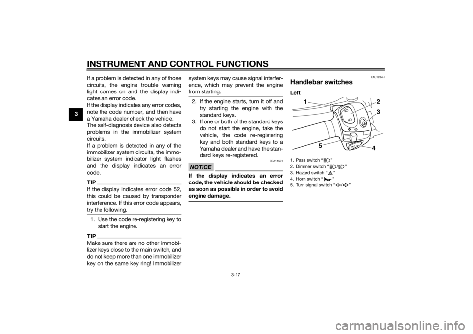
Handle bar switchesLeft1. Pass switch “ ”
2. Dimmer switch “ / ”
3. Hazard switch “ ”
4. Horn switch “ ”
5. Turn signal switch “ / ”
5
43
2
1
U2CEE0E0.book Page 17 Wednesday, August 27, 2014 11:11 AM
Page 46 of 112
INSTRUMENT AND CONTROL FUNCTIONS
3-31
3
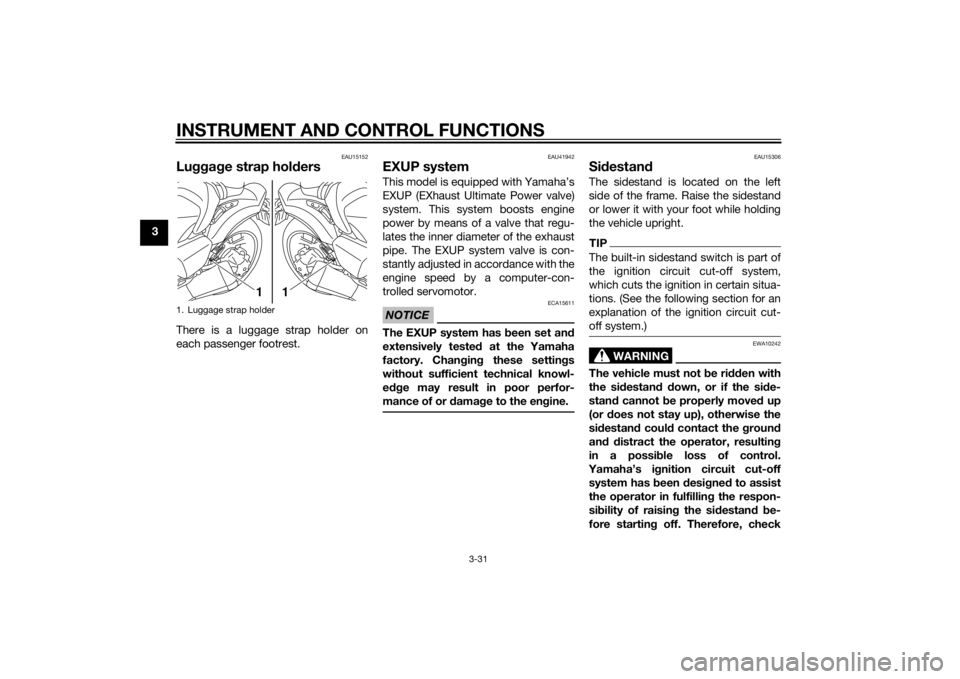
EAU15152
Luggage strap hol dersThere is a luggage strap holder on
each passenger footrest.
EAU41942
EXUP systemThis model is equipped with Yamaha’s
EXUP (EXhaust Ultimate Power valve)
system. This system boosts engine
power by means of a valve that regu-
lates the inner diameter of the exhaust
pipe. The EXUP system valve is con-
stantly adjusted in accordance with the
engine speed by a computer-con-
trolled servomotor.NOTICE
ECA15611
The EXUP system has been set an d
extensively teste d at the Yamaha
factory. Chan gin g these settin gs
without sufficient technical knowl-
e dge may result in poor perfor-
mance of or damag e to the en gine.
EAU15306
Si destan dThe sidestand is located on the left
side of the frame. Raise the sidestand
or lower it with your foot while holding
the vehicle upright.TIPThe built-in sidestand switch is part of
the ignition circuit cut-off system,
which cuts the ignition in certain situa-
tions. (See the following section for an
explanation of the ignition circuit cut-
off system.)
WARNING
EWA10242
The vehicle must not be ri dden with
the si destan d d own, or if the si de-
stan d cannot b e properly moved up
(or does not stay up), otherwise the
si destan d coul d contact the groun d
an d d istract the operator, resultin g
in a possi ble loss of control.
Yamaha’s i gnition circuit cut-off
system has been desi gne d to assist
the operator in fulfillin g the respon-
si bility of raisin g the si destan d b e-
fore startin g off. Therefore, check
1. Luggage strap holder
1
1
U2CEE0E0.book Page 31 Wednesday, August 27, 2014 11:11 AM
Page 47 of 112

INSTRUMENT AND CONTROL FUNCTIONS
3-32
3
this system re
gularly an d have a
Yamaha dealer repair it if it does not
function properly.
EAU44893
I g nition circuit cut-off systemThe ignition circuit cut-off system
(comprising the sidestand switch,
clutch switch and neutral switch) has
the following functions.
It prevents starting when the
transmission is in gear and the
sidestand is up, but the clutch le-
ver is not pulled.
It prevents starting when the
transmission is in gear and the
clutch lever is pulled, but the side-
stand is still down.
It cuts the running engine when
the transmission is in gear and the
sidestand is moved down.
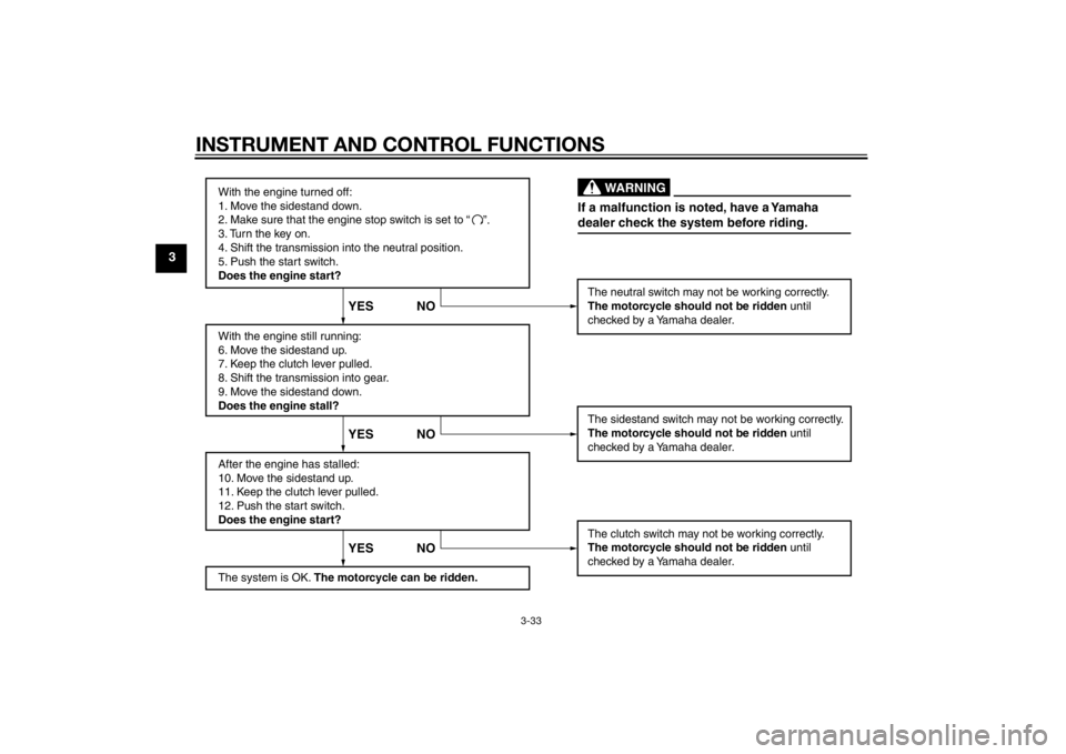
Periodically check the operation of the
ignition circuit cut-off system accord-
ing to the following procedure.
U2CEE0E0.book Page 32 Wednesday, August 27, 2014 11:11 AM
Page 48 of 112
INSTRUMENT AND CONTROL FUNCTIONS
3-33
3
With the engine turned off:
1. Move the sidestand down.
2. Make sure that the engine stop switch is set to “
3. Turn the key on.
4. Shift the transmission into the neutral position.
5. Push the start switch.
Does the engine start?
With the engine still running:
6. Move the sidestand up.
7. Keep the clutch lever pulled.
8. Shift the transmission into gear.
9. Move the sidestand down.
Does the engine stall?
After the engine has stalled:
10. Move the sidestand up.
11. Keep the clutch lever pulled.
12. Push the start switch.
Does the engine start?
The system is OK. The motorcycle can be ridden. The neutral switch may not be working correctly.
The motorcycle should not be ridden
until
checked by a Yamaha dealer.
The sidestand switch may not be working correctly.
The motorcycle should not be ridden until
checked by a Yamaha dealer.
The clutch switch may not be working correctly.
The motorcycle should not be ridden until
checked by a Yamaha dealer.
YES NO YES NO YES NO
If a malfunction is noted, have a Yamaha
dealer check the system before riding.
WARNING
”.
U2CEE0E0.book Page 33 Wednesday, August 27, 2014 11:11 AM
Page 49 of 112
FOR YOUR SAFETY – PRE-OPERATION CHECKS
4-1
4
EAU15598
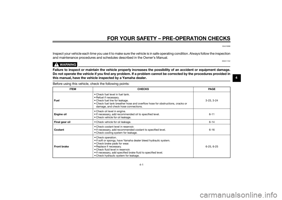
Inspect your vehicle each time you use it to make sure the vehicle is in safe operating condition. Always follow the inspection
and maintenance procedures and schedules described in the Owner’s Manual.
WARNING
EWA11152
Failure to inspect or maintain the vehicle properly increases the possibility of an acci dent or equipment damag e.
Do not operate the vehicle if you fin d any pro blem. If a pro blem cannot be corrected b y the proce dures provi ded in
this manual, have the vehicle inspecte d b y a Yamaha dealer.Before using this vehicle, check the following points:
ITEM CHECKS PAGE
Fuel • Check fuel level in fuel tank.
• Refuel if necessary.
• Check fuel line for leakage.
• Check fuel tank breather hose and overflow hose for obstructions, cracks or
damage, and check hose connections. 3-23, 3-24
En gine oil • Check oil level in engine.
• If necessary, add recommended oil to specified level.
• Check vehicle for oil leakage. 6-11
Final gear oil • Check vehicle for oil leakage. 6-14
Coolant • Check coolant level in reservoir.
• If necessary, add recommended coolant to specified level.
• Check cooling system for leakage. 6-16
Front brake • Check operation.
• If soft or spongy, have Yamaha dealer bleed hydraulic system.
• Check brake pads for wear.
• Replace if necessary.
• Check fluid level in reservoir.
• If necessary, add specified brake fluid to specified level.
• Check hydraulic system for leakage. 6-25, 6-25
U2CEE0E0.book Page 1 Wednesday, August 27, 2014 11:11 AM
Page 53 of 112
OPERATION AND IMPORTANT RIDING POINTS
5-2
5
NOTICE
ECA11834
If a warning or in dicator li ght does
not come on initially when the key is
turne d to “ON”, or if a warnin g or in-
d icator li ght remains on, see pa ge
3-4 for the correspon din g warnin g
an d in dicator li ght circuit check.
The ABS warning light should
come on when the main switch is
turned to “ON” and then go off af-
ter traveling at a speed of 10 km/h
(6 mi/h) or higher.
NOTICE
ECA17682
If the ABS warnin g li ght does not
come on an d then go off as ex-
plaine d a bove, see pa ge 3-4 for the
warnin g li ght circuit check.2. Shift the transmission into the
neutral position. The neutral indi-
cator light should come on. If not,
ask a Yamaha dealer to check the
electrical circuit.
3. Start the engine by pushing the start switch. If the engine fails to start, release
the start switch, wait a few sec-
onds, and then try again. Each
starting attempt should be as
short as possible to preserve the
battery. Do not crank the engine
more than 10 seconds on any one
attempt.
NOTICE
ECA11043
For maximum en
gine life, never ac-
celerate har d when the en gine is
col d!
EAU16673
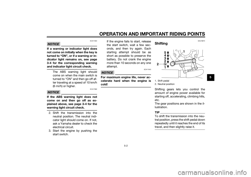
Shiftin gShifting gears lets you control the
amount of engine power available for
starting off, accelerating, climbing hills,
etc.
The gear positions are shown in the il-
lustration.TIPTo shift the transmission into the neu-
tral position, press the shift pedal down
repeatedly until it reaches the end of its
travel, and then slightly raise it.1. Shift pedal
2. Neutral position
1
2
2 3
4 5N1
U2CEE0E0.book Page 2 Wednesday, August 27, 2014 11:11 AM
Page 55 of 112

OPERATION AND IMPORTANT RIDING POINTS
5-4
5
1000–1600 km (600–1000 mi)
Avoid prolonged operation above 5700
r/min.
1600 km (1000 mi) an
d b eyon d
The vehicle can now be operated nor-
mally.
NOTICE
ECA10311
Keep the en gine speed out of
the tachometer re d zone.
If any en gine trou ble shoul d oc-
cur durin g the en gine break-in
period , imme diately have a
Yamaha dealer check the vehi-
cle.
EAU17214
Parkin gWhen parking, stop the engine, and
then remove the key from the main
switch.
WARNING
EWA10312
Since the en gine an d exhaust
system can b ecome very hot,
park in a place where ped estri-
ans or chil dren are not likely to
touch them an d b e burne d.
Do not park on a slope or on soft
groun d, otherwise the vehicle
may overturn, increasin g the
risk of a fuel leak an d fire.
Do not park near grass or other
flamma ble materials which
mi ght catch fire.
U2CEE0E0.book Page 4 Wednesday, August 27, 2014 11:11 AM
Page 65 of 112
PERIODIC MAINTENANCE AND ADJUSTMENT
6-10
6
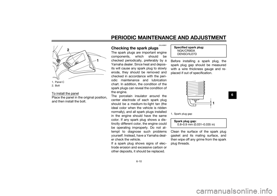
To install the panel
Place the panel in the original position,
and then install the bolt.
EAU46681
Checkin
g the spark plu gsThe spark plugs are important engine
components, which should be
checked periodically, preferably by a
Yamaha dealer. Since heat and depos-
its will cause any spark plug to slowly
erode, they should be removed and
checked in accordance with the peri-
odic maintenance and lubrication
chart. In addition, the condition of the
spark plugs can reveal the condition of
the engine.
The porcelain insulator around the
center electrode of each spark plug
should be a medium-to-light tan (the
ideal color when the vehicle is ridden
normally), and all spark plugs installed
in the engine should have the same
color. If any spark plug shows a dis-
tinctly different color, the engine could
be operating improperly. Do not at-
tempt to diagnose such problems
yourself. Instead, have a Yamaha deal-
er check the vehicle.
If a spark plug shows signs of elec-
trode erosion and excessive carbon or
other deposits, it should be replaced. Before installing a spark plug, the
spark plug gap should be measured
with a wire thickness gauge and re-
placed if out of specification.
Clean the surface of the spark plug
gasket and its mating surface, and
then wipe off any grime from the spark
plug threads.
1. Panel C
2. Bolt
1
2
Specified
spark plu g:
NGK/CR9EIA
DENSO/IU27D
1. Spark plug gap
Spark plu g g ap:
0.8–0.9 mm (0.031–0.035 in)
1
U2CEE0E0.book Page 10 Wednesday, August 27, 2014 11:11 AM
Page 66 of 112
PERIODIC MAINTENANCE AND ADJUSTMENT
6-11
6
TIPIf a torque wrench is not available
when installing a spark plug, a good
estimate of the correct torque is 1/4–
1/2 turn past finger tight. However, the
spark plug should be tightened to the
specified torque as soon as possible.NOTICE
ECA10841
Do not use any tools to remove or in-
stall the spark plug cap, otherwise
the i gnition coil coupler may get
d amag ed . The spark plu g cap may
b e difficult to remove because the
ru bber seal on the en d of the cap fits
ti g htly. To remove the spark plu g
cap, simply twist it b ack and forth
while pullin g it out; to install it, twist
it back an d forth while pushin g it in.
EAU19909
En gine oil an d oil filter car-
tri dgeThe engine oil level should be checked
before each ride. In addition, the oil
must be changed and the oil filter car-
tridge replaced at the intervals speci-
fied in the periodic maintenance and
lubrication chart.
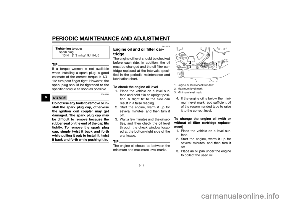
To check the en gine oil level
1. Place the vehicle on a level sur- face and hold it in an upright posi-
tion. A slight tilt to the side can
result in a false reading.
2. Start the engine, warm it up for several minutes, and then turn it
off.
3. Wait a few minutes until the oil set- tles, and then check the oil level
through the check window locat-
ed at the bottom-right side of the
crankcase.TIPThe engine oil should be between the
minimum and maximum level marks.
4. If the engine oil is below the mini-mum level mark, add sufficient oil
of the recommended type to raise
it to the correct level.
To chan ge the en gine oil (with or
without oil filter cartri dge replace-
ment) 1. Place the vehicle on a level sur- face.
2. Start the engine, warm it up for several minutes, and then turn it
off.
3. Place an oil pan under the engine to collect the used oil.
Tightenin g torque:
Spark plug:
13 Nm (1.3 m·kgf, 9.4 ft·lbf)
1. Engine oil level check window
2. Maximum level mark
3. Minimum level mark
23
1
U2CEE0E0.book Page 11 Wednesday, August 27, 2014 11:11 AM