cruise control YAMAHA VX CRUISER 2014 Owners Manual
[x] Cancel search | Manufacturer: YAMAHA, Model Year: 2014, Model line: VX CRUISER, Model: YAMAHA VX CRUISER 2014Pages: 98, PDF Size: 4.01 MB
Page 3 of 98
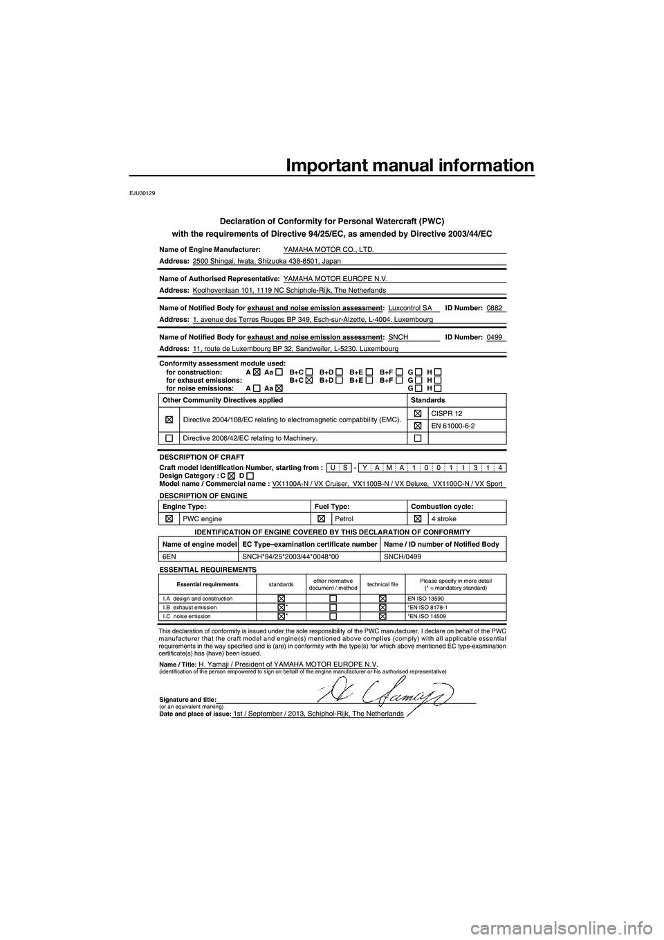
Important manual information
EJU30129
Declaration of Conformity for Personal Watercraft (PWC)
with the requirements of Directive 94/25/EC, as amended by Directive 200\
3/44/EC
Name of Engine Manufacturer: YAMAHA MOTOR CO., LTD.
Name / Title:H. Yamaji / President of YAMAHA MOTOR EUROPE N.V.
Address:
2500 Shingai, Iwata, Shizuoka 438-8501, Japan
Name of Authorised Representative: YAMAHA MOTOR EUROPE N.V.
Address: Koolhovenlaan 101, 1119 NC Schiphole-Rijk, The Netherlands
Name of Notified Body for exhaust and noise emission assessment: Luxcontrol SA
Address: 1. avenue des Terres Rouges BP 349, Esch-sur-Alzette, L-4004. Luxembourg\
Name of Notified Body for exhaust and noise emission assessment: SNCH
VX1100A-N / VX Cruiser, VX1100B-N / VX Deluxe, VX1100C-N / VX Sport
0882
0499
ID Number:
ID Number:
Address: 11, route de Luxembourg BP 32, Sandweiler, L-5230. Luxembourg
US-YAMA1001 I 314
Conformity assessment module used:
for construction:
for exhaust emissions:
for noise emissions:
DESCRIPTION OF CRAFT
DESCRIPTION OF ENGINE A
A
Craft model Identification Number, starting from :
Model name / Commercial name : C
Design Category : Other Community Directives applied
Directive 2004/108/EC relating to electromagnetic compatibility (EMC).\
CISPR 12
Directive 2006/42/EC relating to Machinery. Standards
EN 61000-6-2
D
Aa
AaB+C
B+CB+D
B+D B+E
B+EB+F
B+FG
G
GH
H
H
Engine Type:
PWC engine Combustion cycle:
4 stroke
Fuel Type:
Petrol
ESSENTIAL REQUIREMENTS
IDENTIFICATION OF ENGINE COVERED BY THIS DECLARATION OF CONFORMITY
Name of engine model
6EN Name / ID number of Notified Body
SNCH/0499
EC Type–examination certificate number
SNCH*94/25*2003/44*0048*00
(identification of the person empowered to sign on behalf of the engine\
manufacturer or his authorised representative)
Signature and title:(or an equivalent marking)Date and place of issue:1st / September / 2013, Schiphol-Rijk, The Netherlands
Essential requirements
standardsother normative
document / method technical filePlease specify in more detail
(* = mandatory standard)
I.A design and construction EN ISO 13590
I.B exhaust emission *EN ISO 8178-1
I.C noise emission *EN ISO 14509
*
*
This declaration of conformity is issued under the sole responsibility o\
f the PWC manufacturer. I declare on behalf of the PWC
manufacturer that the craft model and engine(s) mentioned above compli\
es (comply) with all applicable essential
requirements in the way specified and is (are) in conformity with the \
type(s) for which above mentioned EC type-examination
certificate(s) has (have) been issued.
ID Number:
ID Number:
UF2P71E0.book Page 1 Wednesday, July 10, 2013 5:37 PM
Page 5 of 98
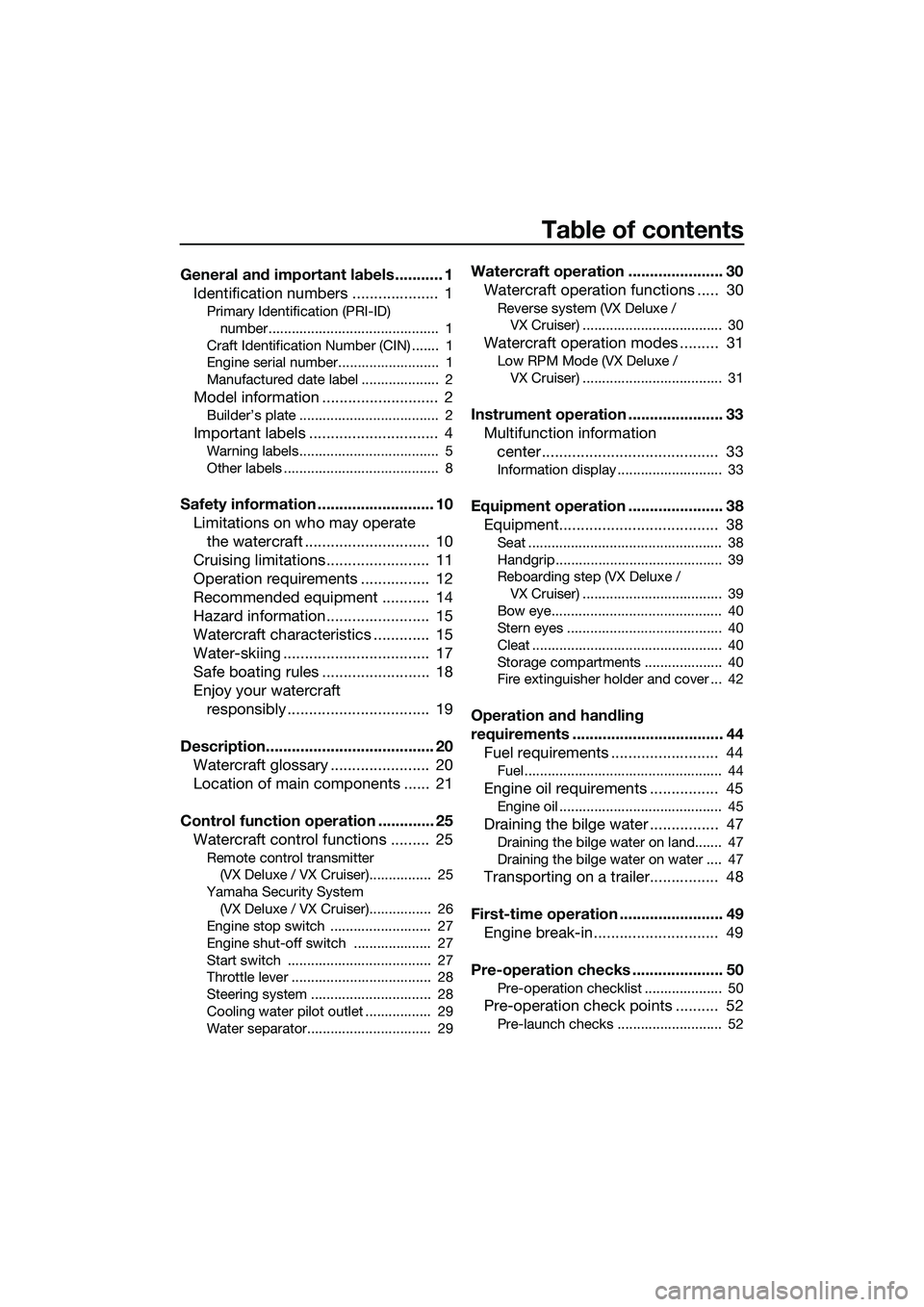
Table of contents
General and important labels ........... 1Identification numbers .................... 1
Primary Identification (PRI-ID)
number............................................ 1
Craft Identification Number (CIN) ....... 1
Engine serial number.......................... 1
Manufactured date label .................... 2
Model information ........................... 2
Builder’s plate .................................... 2
Important labels .............................. 4
Warning labels.................................... 5
Other labels ........................................ 8
Safety information ........................... 10 Limitations on who may operate the watercraft ............................. 10
Cruising limitations ........................ 11
Operation requirements ................ 12
Recommended equipment ........... 14
Hazard information........................ 15
Watercraft characteristics ............. 15
Water-skiing .................................. 17
Safe boating rules ......................... 18
Enjoy your watercraft responsibly ................................. 19
Description....................................... 20 Watercraft glossary ....................... 20
Location of main components ...... 21
Control function operation ............. 25 Watercraft control functions ......... 25
Remote control transmitter
(VX Deluxe / VX Cruiser)................ 25
Yamaha Security System (VX Deluxe / VX Cruiser)................ 26
Engine stop switch .......................... 27
Engine shut-off switch .................... 27
Start switch ..................................... 27
Throttle lever .................................... 28
Steering system ............................... 28
Cooling water pilot outlet ................. 29
Water separator................................ 29
Watercraft operation ...................... 30 Watercraft operation functions ..... 30
Reverse system (VX Deluxe /
VX Cruiser) .................................... 30
Watercraft operation modes ......... 31
Low RPM Mode (VX Deluxe /
VX Cruiser) .................................... 31
Instrument operation ...................... 33Multifunction information center ......................................... 33
Information display ........................... 33
Equipment operation ...................... 38Equipment..................................... 38
Seat .................................................. 38
Handgrip........................................... 39
Reboarding step (VX Deluxe /
VX Cruiser) .................................... 39
Bow eye............................................ 40
Stern eyes ........................................ 40
Cleat ................................................. 40
Storage compartments .................... 40
Fire extinguisher holder and cover ... 42
Operation and handling
requirements ................................... 44 Fuel requirements ......................... 44
Fuel................................................... 44
Engine oil requirements ................ 45
Engine oil .......................................... 45
Draining the bilge water ................ 47
Draining the bilge water on land....... 47
Draining the bilge water on water .... 47
Transporting on a trailer................ 48
First-time operation ........................ 49 Engine break-in............................. 49
Pre-operation checks ..................... 50
Pre-operation checklist .................... 50
Pre-operation check points .......... 52
Pre-launch checks ........................... 52
UF2P71E0.book Page 1 Wednesday, July 10, 2013 5:37 PM
Page 15 of 98
General and important labels
9
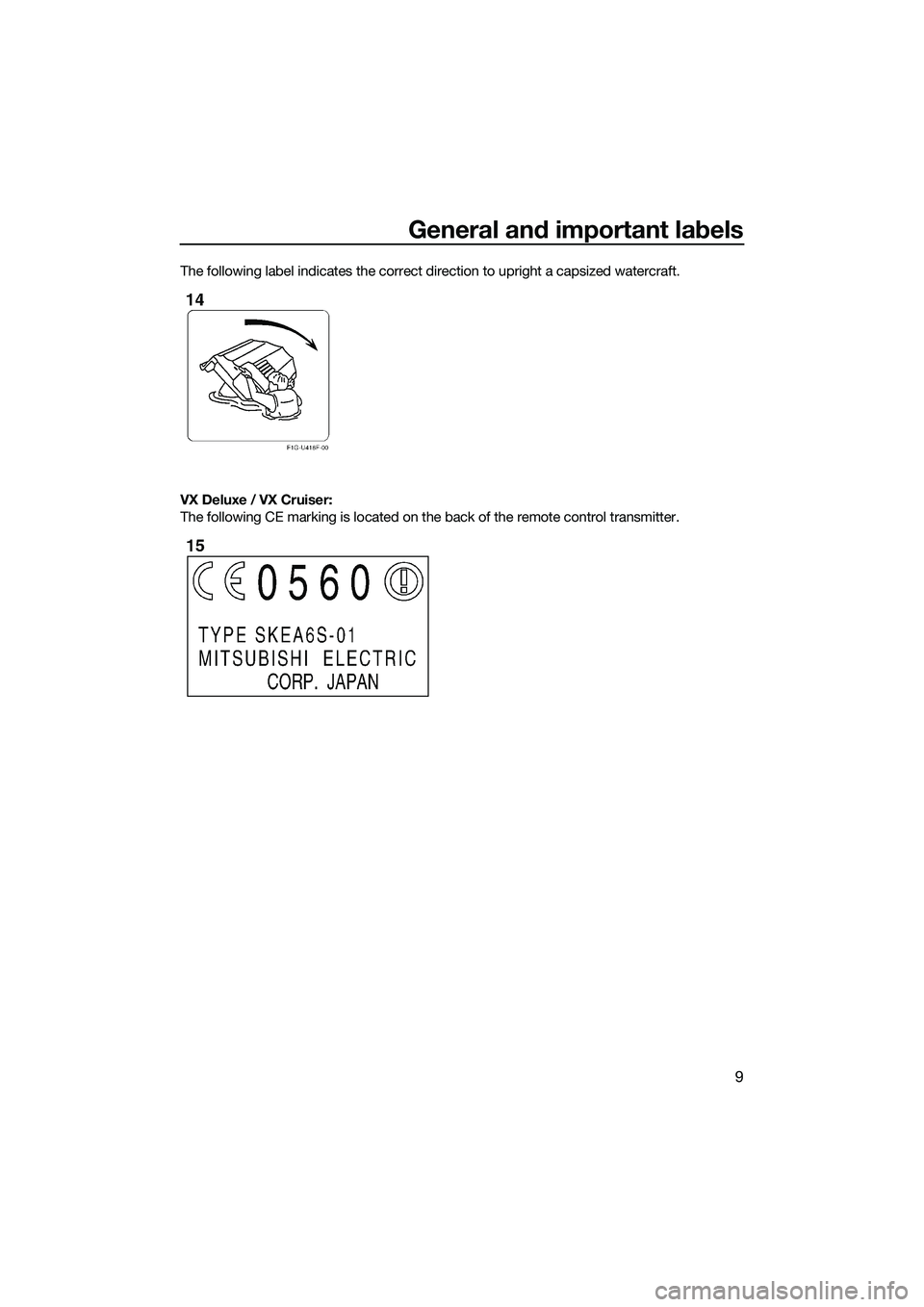
The following label indicates the correct direction to upright a capsized watercraft.
VX Deluxe / VX Cruiser:
The following CE marking is located on the back of the remote control transmitter.
UF2P71E0.book Page 9 Wednesday, July 10, 2013 5:37 PM
Page 22 of 98
Safety information
16
VX Deluxe / VX Cruiser: Do not use the re-
verse function to slow down or stop the
watercraft as it could cause you to lose
control, be ejected, or impact the handle-
bars.
This could increase the risk of back/spinal
injury (paralysis), facial injuries, and broken
legs, ankles, and other bones. You could
also damage the shift mechanism.
VX Deluxe / VX Cruiser: Reverse can be
used to slow down or stop during slow-
speed maneuvering, such as when dock-
ing. Once the engine is idling, shift into re-
verse and gradually increase engine speed.
Make sure that there are no obstacles or
people behind you before shifting into re-
verse.
Keep away from the intake grate while the
engine is on. Items such as long hair, loose
clothing, or PFD straps can become entan-
gled in moving parts, resulting in severe in-
jury or drowning.
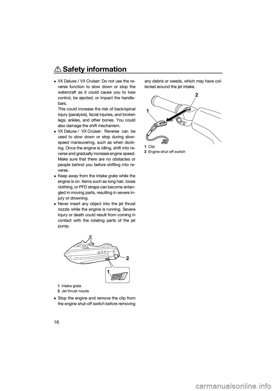
Never insert any object into the jet thrust
nozzle while the engine is running. Severe
injury or death could result from coming in
contact with the rotating parts of the jet
pump.
Stop the engine and remove the clip from
the engine shut-off switch before removingany debris or weeds, which may have col-
lected around the jet intake.
1
Intake grate
2 Jet thrust nozzle
1
2
1Clip
2 Engine shut-off switch
STOP
2
1
UF2P71E0.book Page 16 Wednesday, July 10, 2013 5:37 PM
Page 29 of 98
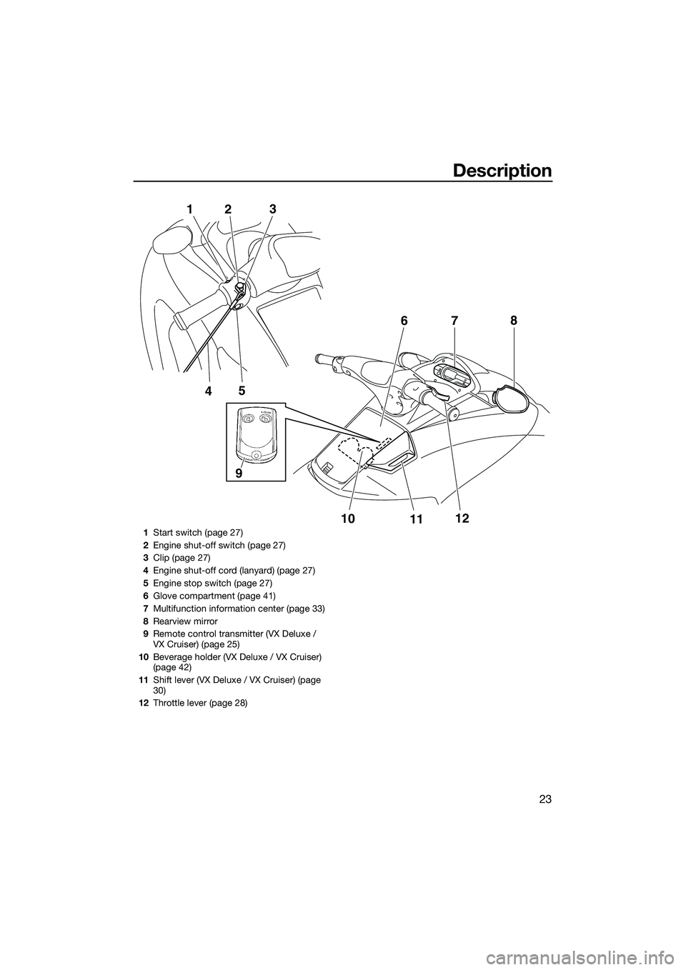
Description
23
5
4
1
2 3
10
1112
7
6
8
9
1
Start switch (page 27)
2 Engine shut-off switch (page 27)
3 Clip (page 27)
4 Engine shut-off cord (lanyard) (page 27)
5 Engine stop switch (page 27)
6 Glove compartment (page 41)
7 Multifunction information center (page 33)
8 Rearview mirror
9 Remote control transmitter (VX Deluxe /
VX Cruiser) (page 25)
10 Beverage holder (VX Deluxe / VX Cruiser)
(page 42)
11 Shift lever (VX Deluxe / VX Cruiser) (page
30)
12 Throttle lever (page 28)
UF2P71E0.book Page 23 Wednesday, July 10, 2013 5:37 PM
Page 31 of 98
Control function operation
25
EJU31025
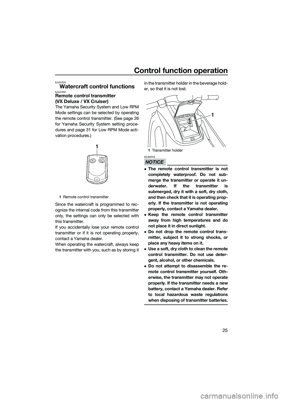
Watercraft control functionsEJU41391Remote control transmitter
(VX Deluxe / VX Cruiser)
The Yamaha Security System and Low RPM
Mode settings can be selected by operating
the remote control transmitter. (See page 26
for Yamaha Security System setting proce-
dures and page 31 for Low RPM Mode acti-
vation procedures.)
Since the watercraft is programmed to rec-
ognize the internal code from this transmitter
only, the settings can only be selected with
this transmitter.
If you accidentally lose your remote control
transmitter or if it is not operating properly,
contact a Yamaha dealer.
When operating the watercraft, always keep
the transmitter with you, such as by storing itin the transmitter holder in the beverage hold-
er, so that it is not lost.
NOTICE
ECJ00753
The remote control transmitter is not
completely waterproof. Do not sub-
merge the transmitter or operate it un-
derwater. If the transmitter is
submerged, dry it with a soft, dry cloth,
and then check that it is operating prop-
erly. If the transmitter is not operating
properly, contact a Yamaha dealer.
Keep the remote control transmitter
away from high temperatures and do
not place it in direct sunlight.
Do not drop the remote control trans-
mitter, subject it to strong shocks, or
place any heavy items on it.
Use a soft, dry cloth to clean the remote
control transmitter. Do not use deter-
gent, alcohol, or other chemicals.
Do not attempt to disassemble the re-
mote control transmitter yourself. Oth-
erwise, the transmitter may not operate
properly. If the transmitter needs a new
battery, contact a Yamaha dealer. Refer
to local hazardous waste regulations
when disposing of transmitter batteries.
1
Remote control transmitter
1Transmitter holder
1
UF2P71E0.book Page 25 Wednesday, July 10, 2013 5:37 PM
Page 32 of 98
Control function operation
26
EJU31385Yamaha Security System (VX Deluxe / VX Cruiser)
The Yamaha Security System functions to
help prevent unauthorized use or theft of the
watercraft. The lock and unlock modes of the
security system can be selected by operating
the remote control transmitter that is included
with this watercraft. The engine cannot be
started if the lock mode of the security sys-
tem is selected. The engine can only be start-
ed if the unlock mode is selected. (See page
25 for information on the remote control
transmitter.)
TIP:
The Yamaha Security System settings can
only be selected while the engine is stopped.
EJU36107Yamaha Security System settings
The Yamaha Security System settings will be
confirmed by the number of beeps when the
remote control transmitter is operated, and
by the “SECURITY” indicator light of the mul-
tifunction information center. (See page 33
for information on the multifunction informa-
tion center.)
TIP:
The beeper sounds two times for the nor-
mal operation mode or three times for the
Low RPM Mode. (See page 31 for Low
RPM Mode activation procedures.)
If the remote control transmitter is operated
while the multifunction information center
is in the standby state, the center will per-
form the initial operation, and then the set-
ting is selected.
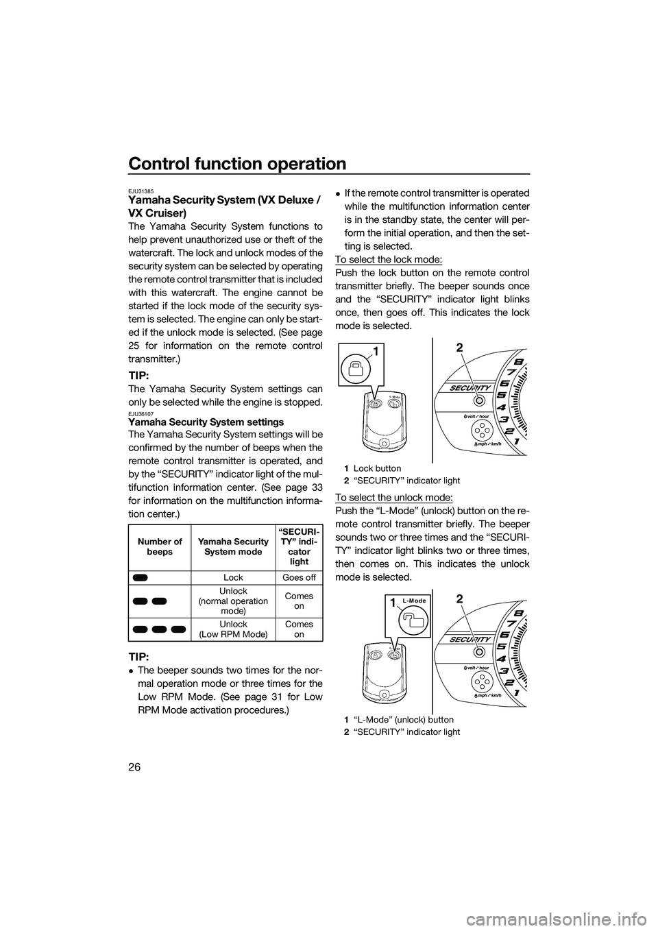
To select the lock mode:
Push the lock button on the remote control
transmitter briefly. The beeper sounds once
and the “SECURITY” indicator light blinks
once, then goes off. This indicates the lock
mode is selected.
To select the unlock mode:
Push the “L-Mode” (unlock) button on the re-
mote control transmitter briefly. The beeper
sounds two or three times and the “SECURI-
TY” indicator light blinks two or three times,
then comes on. This indicates the unlock
mode is selected.
Number of beeps Yamaha Security
System mode “SECURI-
TY” indi- cator light
Lock Goes off
Unlock
(normal operation mode) Comes
on
Unlock
(Low RPM Mode) Comes
on
1 Lock button
2 “SECURITY” indicator light
1 “L-Mode” (unlock) button
2 “SECURITY” indicator light
21
2L-Mode1
UF2P71E0.book Page 26 Wednesday, July 10, 2013 5:37 PM
Page 34 of 98
![YAMAHA VX CRUISER 2014 Owners Manual Control function operation
28
will not start. Also, the starter motor could
be damaged.
[ECJ01041]
The engine will not start under any of the fol-
lowing conditions:
Clip is removed from the engin YAMAHA VX CRUISER 2014 Owners Manual Control function operation
28
will not start. Also, the starter motor could
be damaged.
[ECJ01041]
The engine will not start under any of the fol-
lowing conditions:
Clip is removed from the engin](/img/51/52133/w960_52133-33.png)
Control function operation
28
will not start. Also, the starter motor could
be damaged.
[ECJ01041]
The engine will not start under any of the fol-
lowing conditions:
Clip is removed from the engine shut-off
switch.
Throttle lever is squeezed.
VX Deluxe / VX Cruiser: Lock mode of the
Yamaha Security System has been select- ed. (See page 26 for Yamaha Security Sys-
tem setting procedures.)
EJU31212Throttle lever
The throttle lever increases the engine speed
when the lever is squeezed.
The throttle lever returns automatically to its
fully closed (idle) position when released.
EJU31262Steering system
By turning the handlebars in the direction you
wish to travel, the angle of the jet thrust noz-
zle is changed, and the direction of the water-
craft is changed accordingly.
Since the strength of the jet thrust determines
the speed and degree of a turn, throttle must
always be applied when attempting a turn,
except at trolling speed.
This model is equipped with the Yamaha En-
gine Management System (YEMS) that in-
cludes an off-throttle steering (OTS) system.
It will activate at planing speeds should you
attempt to steer the watercraft after releasing
the throttle lever. The OTS system assists in
turning by continuing to supply some thrust
while the watercraft is decelerating, but you
can turn more sharply if you apply throttle
while turning the handlebars. The OTS sys-
tem does not function below planing speeds
or when the engine is off. Once the engine
slows down, the watercraft will no longer turn
1 Start switch
1 Throttle lever
START
1
1
1Handlebar
2 Jet thrust nozzle
2
1
UF2P71E0.book Page 28 Wednesday, July 10, 2013 5:37 PM
Page 36 of 98

Watercraft operation
30
EJU40012
Watercraft operation functions
EJU40521Reverse system (VX Deluxe /
VX Cruiser)
WARNING
EWJ01231
Do not use the reverse function to slow
down or stop the watercraft as it could
cause you to lose control, be ejected, or
impact the handlebars.
Make sure that there are no obstacles or
people behind you before shifting into
reverse.
Do not touch the reverse gate while the
shift lever is being operated, otherwise
you could be pinched.
When the shift lever is moved to the reverse
position, the reverse gate lowers and deflects
the water jet being discharged from the jet
thrust nozzle. This allows the watercraft to
move in reverse.
To shift into reverse:
(1) Release the throttle lever and let the en-gine speed return to idle.
(2) Pull the shift lever rearward until it stops in the reverse position. The reverse gate will lower and the watercraft will start
moving in reverse at trolling speed.
To shift into forward:
(1) Release the throttle lever and let the en- gine speed return to idle.
(2) Push the shift lever forward until it stops in the forward position. The reverse gate
will rise and the watercraft will start mov-
ing forward at trolling speed.
1Shift lever
2 Reverse position
3 Forward position
1 Reverse gate
2 Forward position
3 Reverse position
1
23
13
2
UF2P71E0.book Page 30 Wednesday, July 10, 2013 5:37 PM
Page 37 of 98
Watercraft operation
31
EJU40001
Watercraft operation modes
EJU31418Low RPM Mode (VX Deluxe /
VX Cruiser)
The Low RPM Mode is a function that limits
the maximum engine speed to approximately
90% of the maximum engine speed in the
normal mode.
The Low RPM Mode can only be activated
and deactivated by operating the remote
control transmitter that is included with this
watercraft. (See page 25 for information on
the remote control transmitter.)
TIP:
The Low RPM Mode can only be activated
when the engine is stopped in the unlock
mode of the Yamaha Security System.
Activating and deactivating the Low RPM
Mode
Activation of the Low RPM Mode will be con-
firmed by the number of beeps when the re-
mote control transmitter is operated, and by
the “L-MODE” indicator light of the multifunc-
tion information center. (See page 33 for in-
formation on the mult ifunction information
center.)
TIP:
If the remote control transmitter is operated
while the multifunction information center is
in the standby state, the center performs the
initial operation, and then the setting is se-
lected.
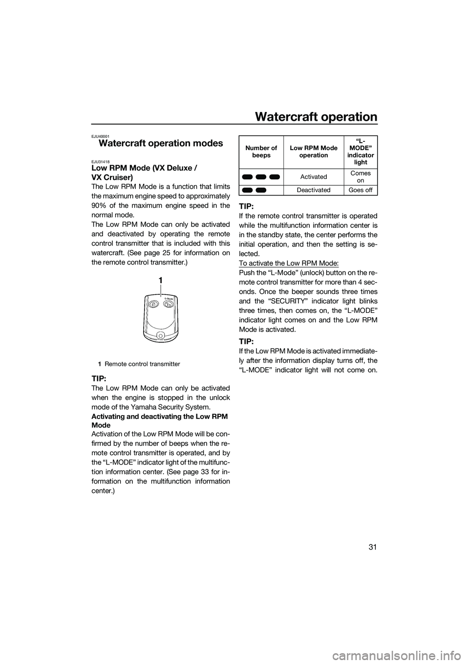
To activate the Low RPM Mode:
Push the “L-Mode” (unlock) button on the re-
mote control transmitter for more than 4 sec-
onds. Once the beeper sounds three times
and the “SECURITY” indicator light blinks
three times, then comes on, the “L-MODE”
indicator light comes on and the Low RPM
Mode is activated.
TIP:
If the Low RPM Mode is activated immediate-
ly after the information display turns off, the
“L-MODE” indicator light will not come on.
1 Remote control transmitter
Number of
beeps Low RPM Mode
operation “L-
MODE”
indicator light
Activated Comes
on
Deactivated Goes off
UF2P71E0.book Page 31 Wednesday, July 10, 2013 5:37 PM