stop start YAMAHA VX CRUISER 2014 Owners Manual
[x] Cancel search | Manufacturer: YAMAHA, Model Year: 2014, Model line: VX CRUISER, Model: YAMAHA VX CRUISER 2014Pages: 98, PDF Size: 4.01 MB
Page 5 of 98
Table of contents
General and important labels ........... 1Identification numbers .................... 1
Primary Identification (PRI-ID)
number............................................ 1
Craft Identification Number (CIN) ....... 1
Engine serial number.......................... 1
Manufactured date label .................... 2
Model information ........................... 2
Builder’s plate .................................... 2
Important labels .............................. 4
Warning labels.................................... 5
Other labels ........................................ 8
Safety information ........................... 10 Limitations on who may operate the watercraft ............................. 10
Cruising limitations ........................ 11
Operation requirements ................ 12
Recommended equipment ........... 14
Hazard information........................ 15
Watercraft characteristics ............. 15
Water-skiing .................................. 17
Safe boating rules ......................... 18
Enjoy your watercraft responsibly ................................. 19
Description....................................... 20 Watercraft glossary ....................... 20
Location of main components ...... 21
Control function operation ............. 25 Watercraft control functions ......... 25
Remote control transmitter
(VX Deluxe / VX Cruiser)................ 25
Yamaha Security System (VX Deluxe / VX Cruiser)................ 26
Engine stop switch .......................... 27
Engine shut-off switch .................... 27
Start switch ..................................... 27
Throttle lever .................................... 28
Steering system ............................... 28
Cooling water pilot outlet ................. 29
Water separator................................ 29
Watercraft operation ...................... 30 Watercraft operation functions ..... 30
Reverse system (VX Deluxe /
VX Cruiser) .................................... 30
Watercraft operation modes ......... 31
Low RPM Mode (VX Deluxe /
VX Cruiser) .................................... 31
Instrument operation ...................... 33Multifunction information center ......................................... 33
Information display ........................... 33
Equipment operation ...................... 38Equipment..................................... 38
Seat .................................................. 38
Handgrip........................................... 39
Reboarding step (VX Deluxe /
VX Cruiser) .................................... 39
Bow eye............................................ 40
Stern eyes ........................................ 40
Cleat ................................................. 40
Storage compartments .................... 40
Fire extinguisher holder and cover ... 42
Operation and handling
requirements ................................... 44 Fuel requirements ......................... 44
Fuel................................................... 44
Engine oil requirements ................ 45
Engine oil .......................................... 45
Draining the bilge water ................ 47
Draining the bilge water on land....... 47
Draining the bilge water on water .... 47
Transporting on a trailer................ 48
First-time operation ........................ 49 Engine break-in............................. 49
Pre-operation checks ..................... 50
Pre-operation checklist .................... 50
Pre-operation check points .......... 52
Pre-launch checks ........................... 52
UF2P71E0.book Page 1 Wednesday, July 10, 2013 5:37 PM
Page 6 of 98
Table of contents
Post-launch checks ......................... 58
Operation ......................................... 59Operating your watercraft ............. 59
Getting to know your watercraft ...... 59
Learning to operate your
watercraft ...................................... 59
Riding position ................................. 60
Launching the watercraft ................. 60
Starting the engine on water ............ 60
Stopping the engine ......................... 61
Leaving the watercraft...................... 61
Operating the watercraft .................. 61
Turning the watercraft ...................... 62
Stopping the watercraft ................... 64
Operating the watercraft in reverse (VX Deluxe / VX Cruiser)................ 64
Boarding the watercraft ................... 65
Starting off........................................ 68
Capsized watercraft ......................... 69
Beaching and docking the watercraft ...................................... 70
Operating in weeded areas .............. 70
After removing the watercraft from
the water ....................................... 71
Care and storage............................. 72Post-operation care ...................... 72
Flushing the cooling water
passages....................................... 72
Cleaning the watercraft .................... 73
Battery care ...................................... 73
Long-term storage ........................ 76
Cleaning ........................................... 76
Lubrication ....................................... 76
Rustproofing..................................... 77
Maintenance .................................... 78 Maintenance.................................. 78
Tool kit.............................................. 78
Periodic maintenance chart ............. 79
Engine oil and oil filter ...................... 80
Specifications .................................. 81Specifications ............................... 81
Trouble recovery ............................. 82 Troubleshooting ............................ 82
Troubleshooting chart ...................... 82
Emergency procedures ................ 85
Cleaning the jet intake and
impeller ......................................... 85
Jumping the battery ......................... 86
Replacing the fuses .......................... 86
Towing the watercraft....................... 88
Submerged watercraft ..................... 88
UF2P71E0.book Page 2 Wednesday, July 10, 2013 5:37 PM
Page 29 of 98
Description
23
5
4
1
2 3
10
1112
7
6
8
9
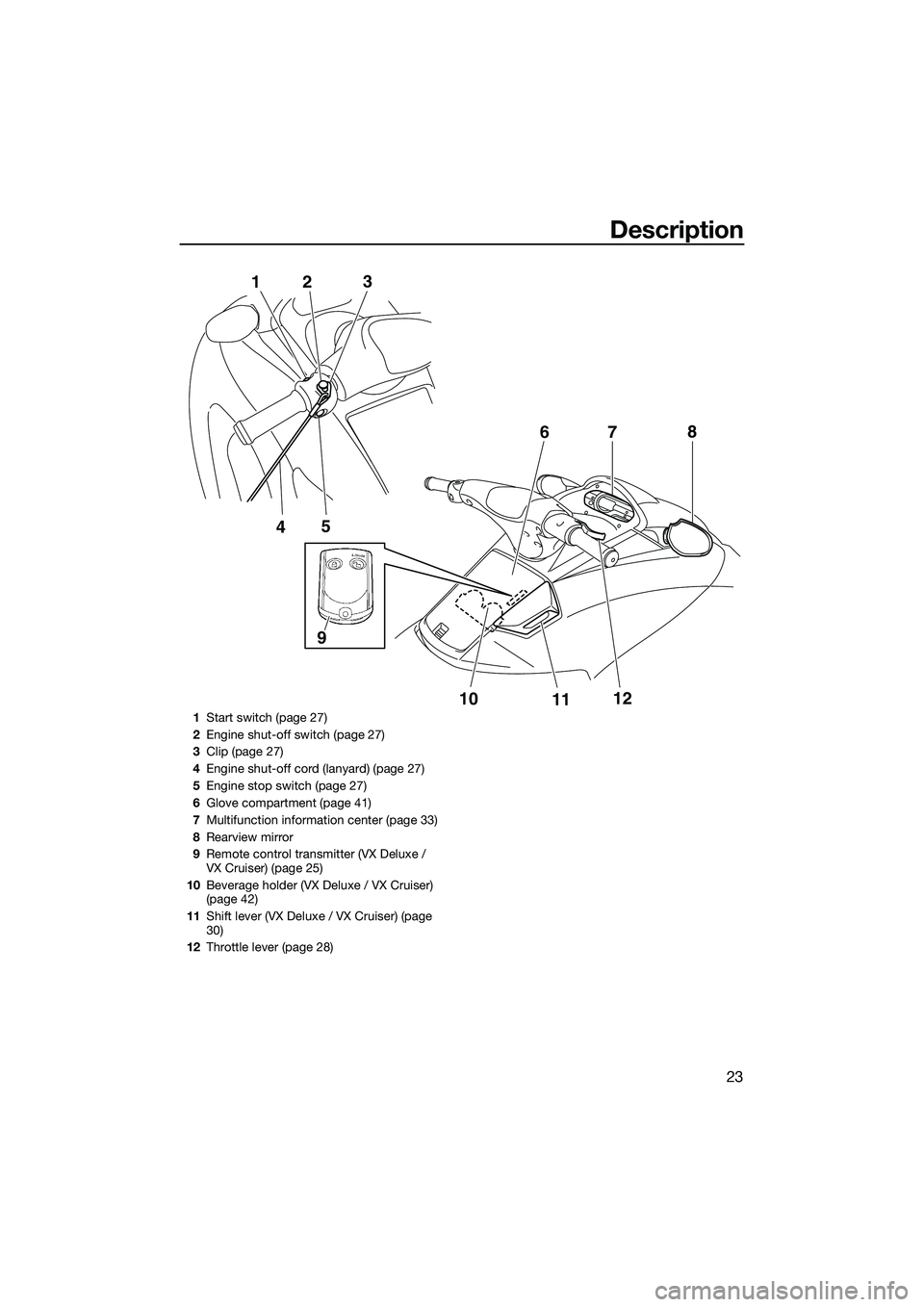
1
Start switch (page 27)
2 Engine shut-off switch (page 27)
3 Clip (page 27)
4 Engine shut-off cord (lanyard) (page 27)
5 Engine stop switch (page 27)
6 Glove compartment (page 41)
7 Multifunction information center (page 33)
8 Rearview mirror
9 Remote control transmitter (VX Deluxe /
VX Cruiser) (page 25)
10 Beverage holder (VX Deluxe / VX Cruiser)
(page 42)
11 Shift lever (VX Deluxe / VX Cruiser) (page
30)
12 Throttle lever (page 28)
UF2P71E0.book Page 23 Wednesday, July 10, 2013 5:37 PM
Page 32 of 98
Control function operation
26
EJU31385Yamaha Security System (VX Deluxe / VX Cruiser)
The Yamaha Security System functions to
help prevent unauthorized use or theft of the
watercraft. The lock and unlock modes of the
security system can be selected by operating
the remote control transmitter that is included
with this watercraft. The engine cannot be
started if the lock mode of the security sys-
tem is selected. The engine can only be start-
ed if the unlock mode is selected. (See page
25 for information on the remote control
transmitter.)
TIP:
The Yamaha Security System settings can
only be selected while the engine is stopped.
EJU36107Yamaha Security System settings
The Yamaha Security System settings will be
confirmed by the number of beeps when the
remote control transmitter is operated, and
by the “SECURITY” indicator light of the mul-
tifunction information center. (See page 33
for information on the multifunction informa-
tion center.)
TIP:
The beeper sounds two times for the nor-
mal operation mode or three times for the
Low RPM Mode. (See page 31 for Low
RPM Mode activation procedures.)
If the remote control transmitter is operated
while the multifunction information center
is in the standby state, the center will per-
form the initial operation, and then the set-
ting is selected.
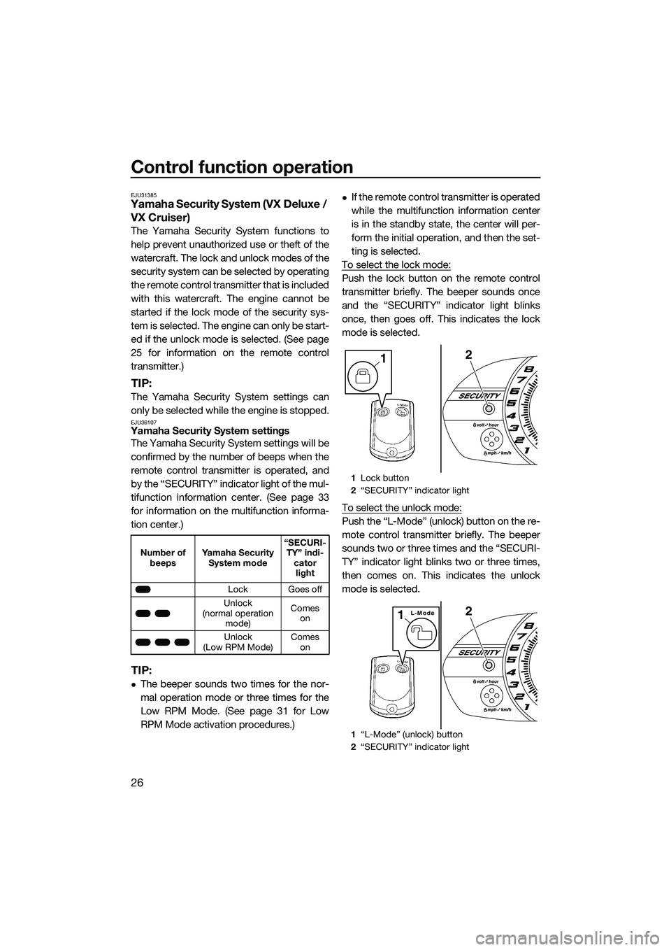
To select the lock mode:
Push the lock button on the remote control
transmitter briefly. The beeper sounds once
and the “SECURITY” indicator light blinks
once, then goes off. This indicates the lock
mode is selected.
To select the unlock mode:
Push the “L-Mode” (unlock) button on the re-
mote control transmitter briefly. The beeper
sounds two or three times and the “SECURI-
TY” indicator light blinks two or three times,
then comes on. This indicates the unlock
mode is selected.
Number of beeps Yamaha Security
System mode “SECURI-
TY” indi- cator light
Lock Goes off
Unlock
(normal operation mode) Comes
on
Unlock
(Low RPM Mode) Comes
on
1 Lock button
2 “SECURITY” indicator light
1 “L-Mode” (unlock) button
2 “SECURITY” indicator light
21
2L-Mode1
UF2P71E0.book Page 26 Wednesday, July 10, 2013 5:37 PM
Page 33 of 98
Control function operation
27
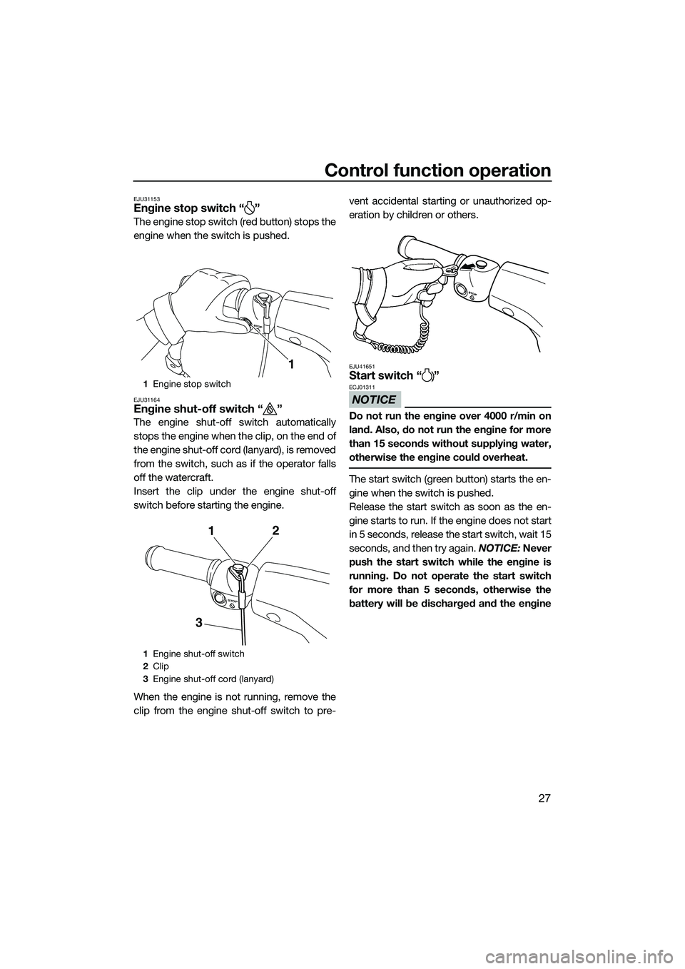
EJU31153Engine stop switch “ ”
The engine stop switch (red button) stops the
engine when the switch is pushed.
EJU31164Engine shut-off switch “ ”
The engine shut-off switch automatically
stops the engine when the clip, on the end of
the engine shut-off cord (lanyard), is removed
from the switch, such as if the operator falls
off the watercraft.
Insert the clip under the engine shut-off
switch before starting the engine.
When the engine is not running, remove the
clip from the engine shut-off switch to pre-vent accidental starting or unauthorized op-
eration by children or others.
EJU41651Start switch “ ”
NOTICE
ECJ01311
Do not run the engine over 4000 r/min on
land. Also, do not run the engine for more
than 15 seconds without supplying water,
otherwise the engine could overheat.
The start switch (green button) starts the en-
gine when the switch is pushed.
Release the start switch as soon as the en-
gine starts to run. If the engine does not start
in 5 seconds, release the start switch, wait 15
seconds, and then try again.
NOTICE: Never
push the start switch while the engine is
running. Do not operate the start switch
for more than 5 seconds, otherwise the
battery will be discharged and the engine
1 Engine stop switch
1 Engine shut-off switch
2 Clip
3 Engine shut-off cord (lanyard)
1
STOP
31
2
UF2P71E0.book Page 27 Wednesday, July 10, 2013 5:37 PM
Page 35 of 98
Control function operation
29
in response to handlebar input until you apply
throttle again or you reach trolling speed.
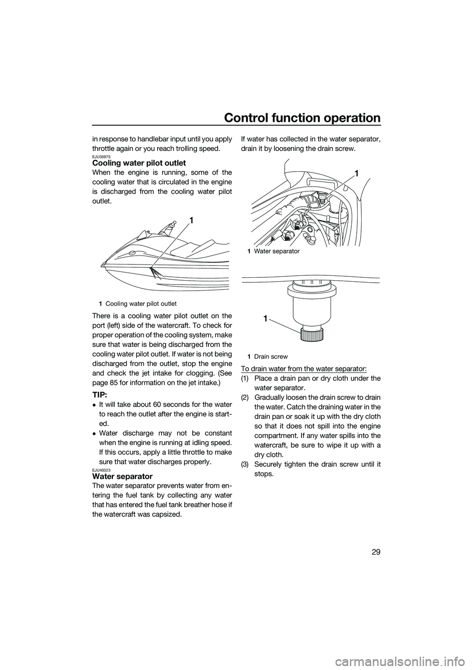
EJU35975Cooling water pilot outlet
When the engine is running, some of the
cooling water that is circulated in the engine
is discharged from the cooling water pilot
outlet.
There is a cooling water pilot outlet on the
port (left) side of the watercraft. To check for
proper operation of the cooling system, make
sure that water is being discharged from the
cooling water pilot outlet. If water is not being
discharged from the outlet, stop the engine
and check the jet intake for clogging. (See
page 85 for information on the jet intake.)
TIP:
It will take about 60 seconds for the water
to reach the outlet after the engine is start-
ed.
Water discharge may not be constant
when the engine is running at idling speed.
If this occurs, apply a little throttle to make
sure that water discharges properly.
EJU40323Water separator
The water separator prevents water from en-
tering the fuel tank by collecting any water
that has entered the fuel tank breather hose if
the watercraft was capsized.If water has collected in the water separator,
drain it by loosening the drain screw.
To drain water from the water separator:
(1) Place a drain pan or dry cloth under the
water separator.
(2) Gradually loosen the drain screw to drain the water. Catch the draining water in the
drain pan or soak it up with the dry cloth
so that it does not spill into the engine
compartment. If any water spills into the
watercraft, be sure to wipe it up with a
dry cloth.
(3) Securely tighten the drain screw until it stops.
1Cooling water pilot outlet
1
1Water separator
1 Drain screw
1
1
UF2P71E0.book Page 29 Wednesday, July 10, 2013 5:37 PM
Page 36 of 98

Watercraft operation
30
EJU40012
Watercraft operation functions
EJU40521Reverse system (VX Deluxe /
VX Cruiser)
WARNING
EWJ01231
Do not use the reverse function to slow
down or stop the watercraft as it could
cause you to lose control, be ejected, or
impact the handlebars.
Make sure that there are no obstacles or
people behind you before shifting into
reverse.
Do not touch the reverse gate while the
shift lever is being operated, otherwise
you could be pinched.
When the shift lever is moved to the reverse
position, the reverse gate lowers and deflects
the water jet being discharged from the jet
thrust nozzle. This allows the watercraft to
move in reverse.
To shift into reverse:
(1) Release the throttle lever and let the en-gine speed return to idle.
(2) Pull the shift lever rearward until it stops in the reverse position. The reverse gate will lower and the watercraft will start
moving in reverse at trolling speed.
To shift into forward:
(1) Release the throttle lever and let the en- gine speed return to idle.
(2) Push the shift lever forward until it stops in the forward position. The reverse gate
will rise and the watercraft will start mov-
ing forward at trolling speed.
1Shift lever
2 Reverse position
3 Forward position
1 Reverse gate
2 Forward position
3 Reverse position
1
23
13
2
UF2P71E0.book Page 30 Wednesday, July 10, 2013 5:37 PM
Page 39 of 98
Instrument operation
33
EJU31459
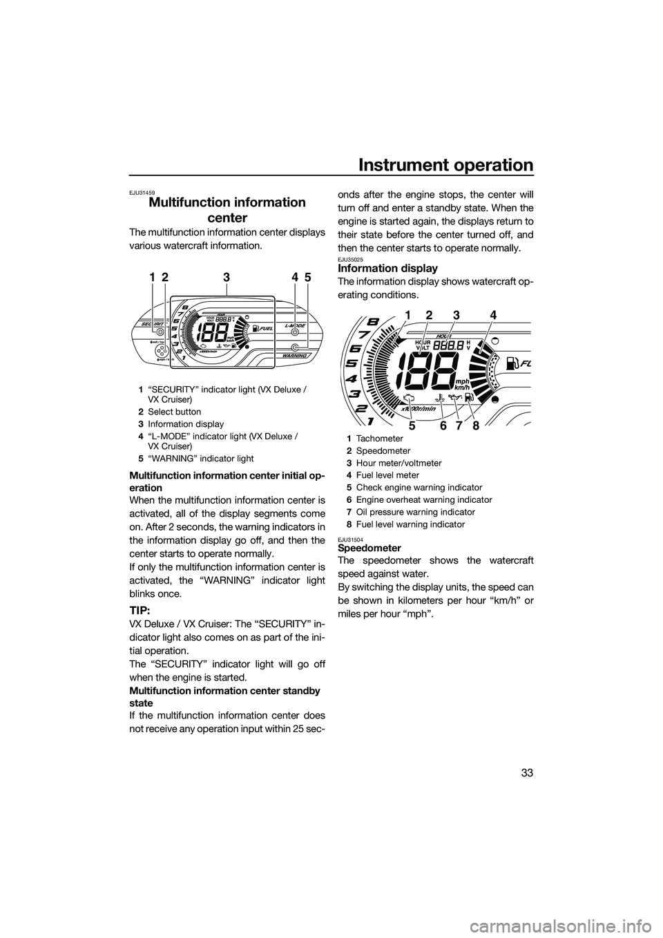
Multifunction information center
The multifunction information center displays
various watercraft information.
Multifunction information center initial op-
eration
When the multifunction information center is
activated, all of the display segments come
on. After 2 seconds, the warning indicators in
the information display go off, and then the
center starts to operate normally.
If only the multifunction information center is
activated, the “WARNING” indicator light
blinks once.
TIP:
VX Deluxe / VX Cruiser: The “SECURITY” in-
dicator light also comes on as part of the ini-
tial operation.
The “SECURITY” indicator light will go off
when the engine is started.
Multifunction information center standby
state
If the multifunction information center does
not receive any operation input within 25 sec- onds after the engine stops, the center will
turn off and enter a standby state. When the
engine is started again, the displays return to
their state before the center turned off, and
then the center starts to operate normally.
EJU35025Information display
The information display shows watercraft op-
erating conditions.
EJU31504Speedometer
The speedometer shows the watercraft
speed against water.
By switching the display units, the speed can
be shown in kilometers per hour “km/h” or
miles per hour “mph”.
1
“SECURITY” indicator light (VX Deluxe /
VX Cruiser)
2 Select button
3 Information display
4 “L-MODE” indicator light (VX Deluxe /
VX Cruiser)
5 “WARNING” indicator light
21345
1Tachometer
2 Speedometer
3 Hour meter/voltmeter
4 Fuel level meter
5 Check engine warning indicator
6 Engine overheat warning indicator
7 Oil pressure warning indicator
8 Fuel level warning indicator
1234
8765
UF2P71E0.book Page 33 Wednesday, July 10, 2013 5:37 PM
Page 42 of 98
Instrument operation
36
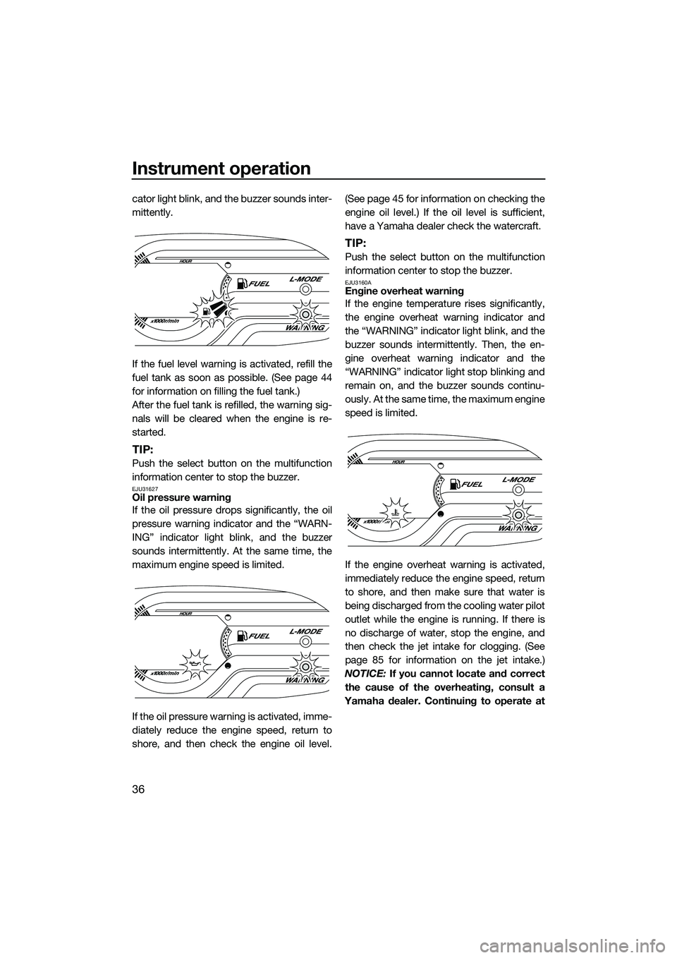
cator light blink, and the buzzer sounds inter-
mittently.
If the fuel level warning is activated, refill the
fuel tank as soon as possible. (See page 44
for information on filling the fuel tank.)
After the fuel tank is refilled, the warning sig-
nals will be cleared when the engine is re-
started.
TIP:
Push the select button on the multifunction
information center to stop the buzzer.
EJU31627Oil pressure warning
If the oil pressure drops significantly, the oil
pressure warning indicator and the “WARN-
ING” indicator light blink, and the buzzer
sounds intermittently. At the same time, the
maximum engine speed is limited.
If the oil pressure warning is activated, imme-
diately reduce the engine speed, return to
shore, and then check the engine oil level.(See page 45 for information on checking the
engine oil level.) If the oil level is sufficient,
have a Yamaha dealer check the watercraft.
TIP:
Push the select button on the multifunction
information center to stop the buzzer.
EJU3160AEngine overheat warning
If the engine temperature rises significantly,
the engine overheat warning indicator and
the “WARNING” indicator light blink, and the
buzzer sounds intermittently. Then, the en-
gine overheat warning indicator and the
“WARNING” indicator light stop blinking and
remain on, and the buzzer sounds continu-
ously. At the same ti
me, the maximum engine
speed is limited.
If the engine overheat warning is activated,
immediately reduce the engine speed, return
to shore, and then make sure that water is
being discharged from the cooling water pilot
outlet while the engine is running. If there is
no discharge of water, stop the engine, and
then check the jet intake for clogging. (See
page 85 for information on the jet intake.)
NOTICE: If you cannot locate and correct
the cause of the overheating, consult a
Yamaha dealer. Continuing to operate at
UF2P71E0.book Page 36 Wednesday, July 10, 2013 5:37 PM
Page 52 of 98
Operation and handling requirements
46
To check the engine oil level:
(1) With the engine stopped, place the wa-tercraft in a precisely level position on
land or launch the watercraft.
(2) Look in all directions, and then start the engine. (See page 60 for information on
starting the engine.)
(3) Run the engine at idling speed for 6 min- utes or more. Run the engine an addi-
tional 5 minutes if the ambient
temperature is 20 °C (68 °F) or less.
(4) Stop the engine.
(5) Remove the seat. (See page 38 for seat removal and installation procedures.)
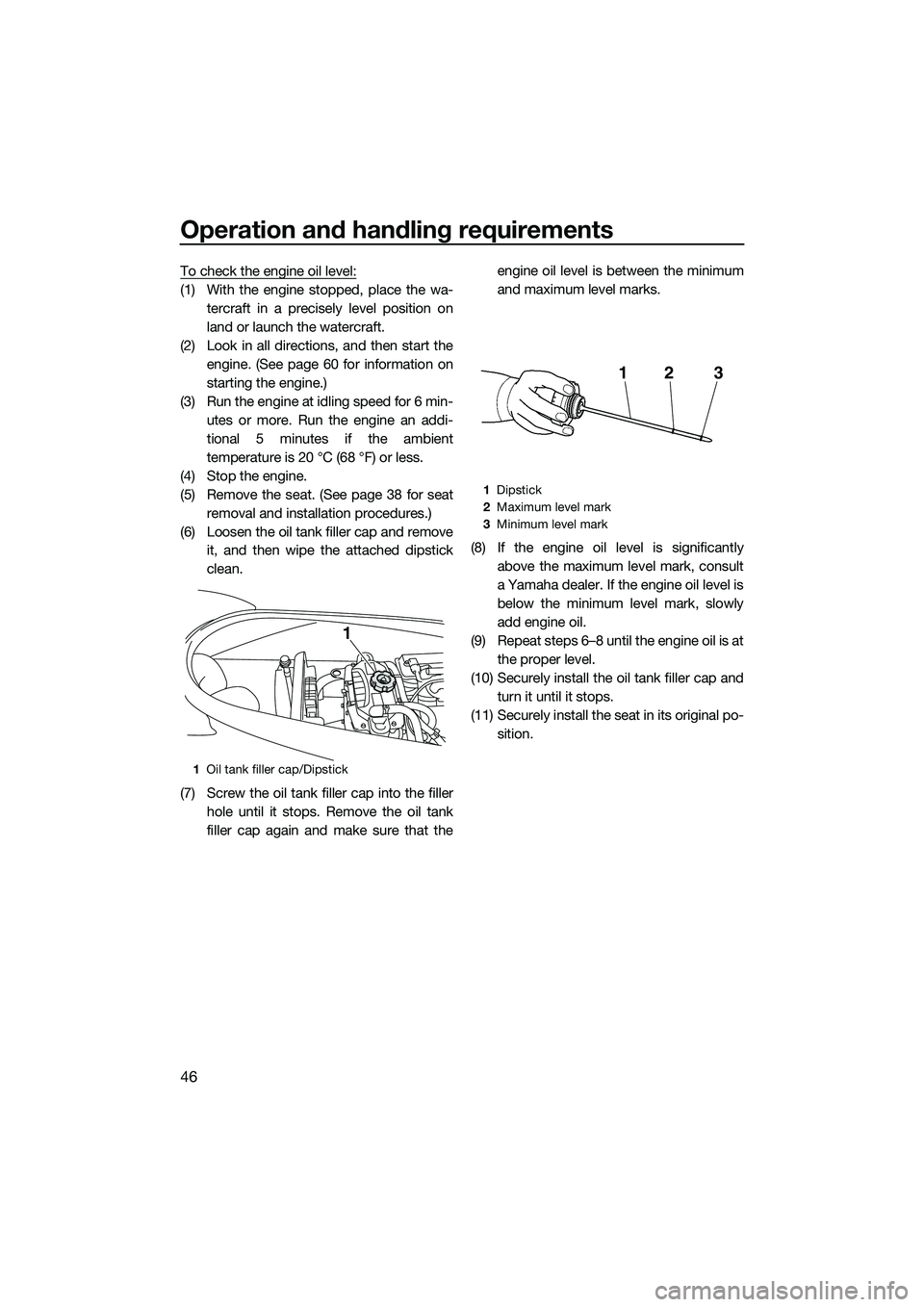
(6) Loosen the oil tank filler cap and remove it, and then wipe the attached dipstick
clean.
(7) Screw the oil tank filler cap into the filler hole until it stops. Remove the oil tank
filler cap again and make sure that the engine oil level is between the minimum
and maximum level marks.
(8) If the engine oil level is significantly above the maximum level mark, consult
a Yamaha dealer. If the engine oil level is
below the minimum level mark, slowly
add engine oil.
(9) Repeat steps 6–8 until the engine oil is at the proper level.
(10) Securely install the oil tank filler cap and turn it until it stops.
(11) Securely install the seat in its original po- sition.
1Oil tank filler cap/Dipstick
1
1Dipstick
2 Maximum level mark
3 Minimum level mark
213
UF2P71E0.book Page 46 Wednesday, July 10, 2013 5:37 PM