fuel cap YAMAHA VX CRUISER HO 2022 Owners Manual
[x] Cancel search | Manufacturer: YAMAHA, Model Year: 2022, Model line: VX CRUISER HO, Model: YAMAHA VX CRUISER HO 2022Pages: 112, PDF Size: 4.8 MB
Page 8 of 112
Table of contents
Operation and handling
requirements ................................... 54Fuel requirements ......................... 54
Fuel................................................... 54
Engine oil requirements ................ 56
Engine oil .......................................... 56
Draining the bilge water ................ 58
Draining the bilge water on land ...... 58
Draining the bilge water on water .... 58
Transporting on a trailer ................ 59
First-time operation ........................ 60 Engine break-in ............................. 60
Pre-operation checks ..................... 61
Pre-operation checklist .................... 61
Pre-operation check points........... 63
Pre-launch checks ........................... 63
Post-launch checks ......................... 68
Operation ......................................... 70 Operating your watercraft ............. 70
Getting to know your watercraft ...... 70
Learning to operate your
watercraft ...................................... 70
Riding position ................................. 71
Launching the watercraft ................. 71
Starting the engine on water ............ 71
Stopping the engine ......................... 72
Leaving the watercraft...................... 72
Operating the watercraft .................. 72
Turning the watercraft ...................... 73
Stopping the watercraft ................... 74
Operating the watercraft in reverse or neutral ...................................... 75
Boarding the watercraft ................... 76
Starting off........................................ 78
Capsized watercraft ......................... 79
Beaching and docking the watercraft ...................................... 80
Operating in weeded areas .............. 80
After removing the watercraft from
the water ....................................... 81
Care and storage ............................ 82Post-operation care ...................... 82
Flushing the cooling water
passages....................................... 82
Cleaning the watercraft .................... 83
Battery care ...................................... 83
Long-term storage ........................ 85
Cleaning ........................................... 85
Lubrication ....................................... 85
Rustproofing ..................................... 86
Maintenance .................................... 87 Maintenance ................................. 87
Removing and installing the engine
cover ............................................. 87
Periodic maintenance chart ............. 89
Engine oil and oil filter ...................... 91
Specifications .................................. 92 Specifications ............................... 92
Trouble recovery ............................. 94 Troubleshooting ............................ 94
Troubleshooting chart ...................... 94
Emergency procedures ................ 97
Cleaning the jet intake and
impeller ......................................... 97
Raising the reverse gate .................. 98
Jumping the battery ......................... 98
Towing the watercraft....................... 99
Submerged watercraft ..................... 99
Index............................................... 101
UF4S71E0.book Page 2 Wednesday, August 4, 2021 5:18 PM
Page 28 of 112

Description
20
EJU31012
Location of main components
Exterior
12
3 4
6
7
12910
8
1113
5
1Hood
2 Glove compartment (page 51)
3 Front seat (page 47)
4 Rear seat (page 47)
5 Handgrip (page 48)
6 Footwell
7 Pull-up cleat (VX LIMITED HO) (page 50)
8 Sponson
9 Gunwale
10 Pull-up cleat (page 50)
11 Cooling water pilot outlet (page 26)
12 Fuel filler cap (page 54)
13 Bow eye (page 49)
UF4S71E0.book Page 20 Wednesday, August 4, 2021 5:18 PM
Page 31 of 112
Description
23
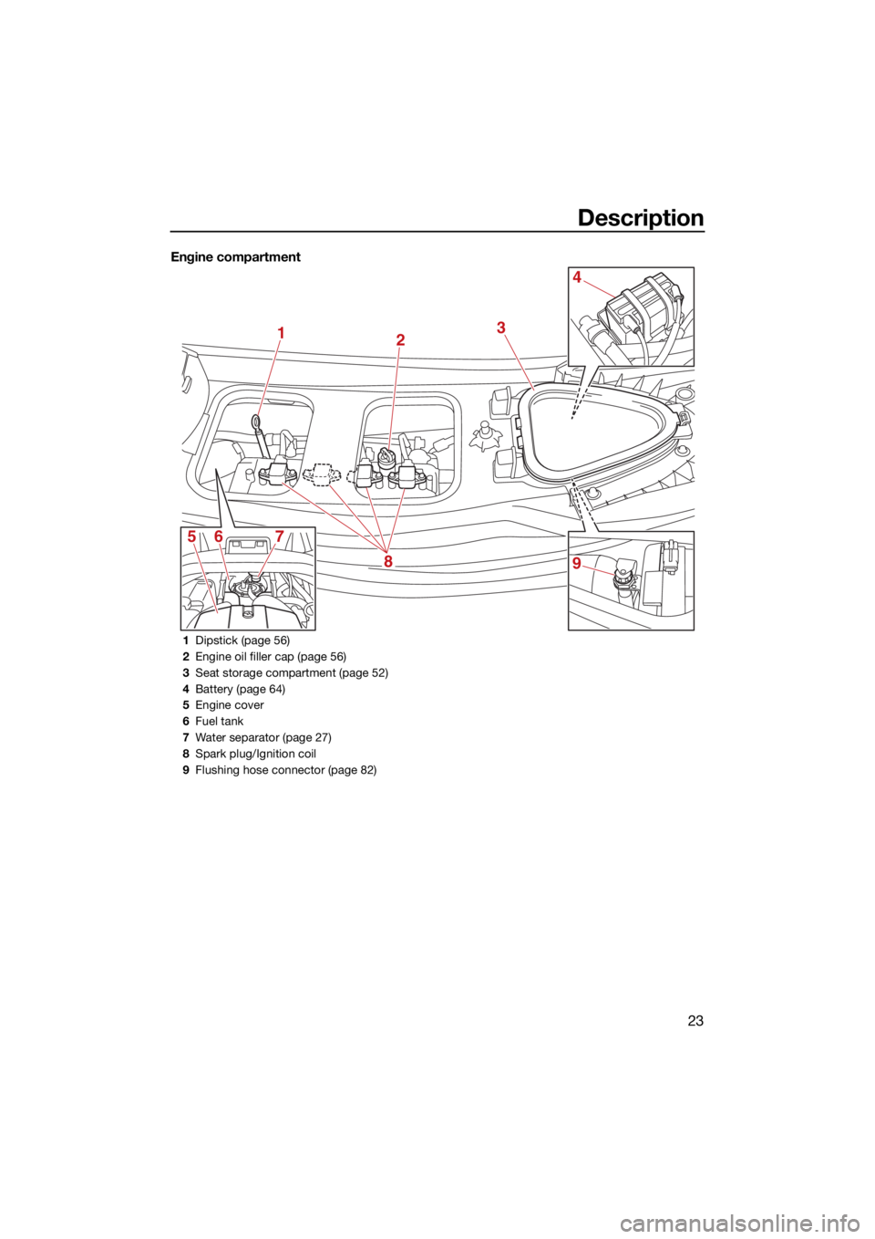
Engine compartment
12
8
567 3
4
9
1
Dipstick (page 56)
2 Engine oil filler cap (page 56)
3 Seat storage compartment (page 52)
4 Battery (page 64)
5 Engine cover
6 Fuel tank
7 Water separator (page 27)
8 Spark plug/Ignition coil
9 Flushing hose connector (page 82)
UF4S71E0.book Page 23 Wednesday, August 4, 2021 5:18 PM
Page 35 of 112
Control function operation
27
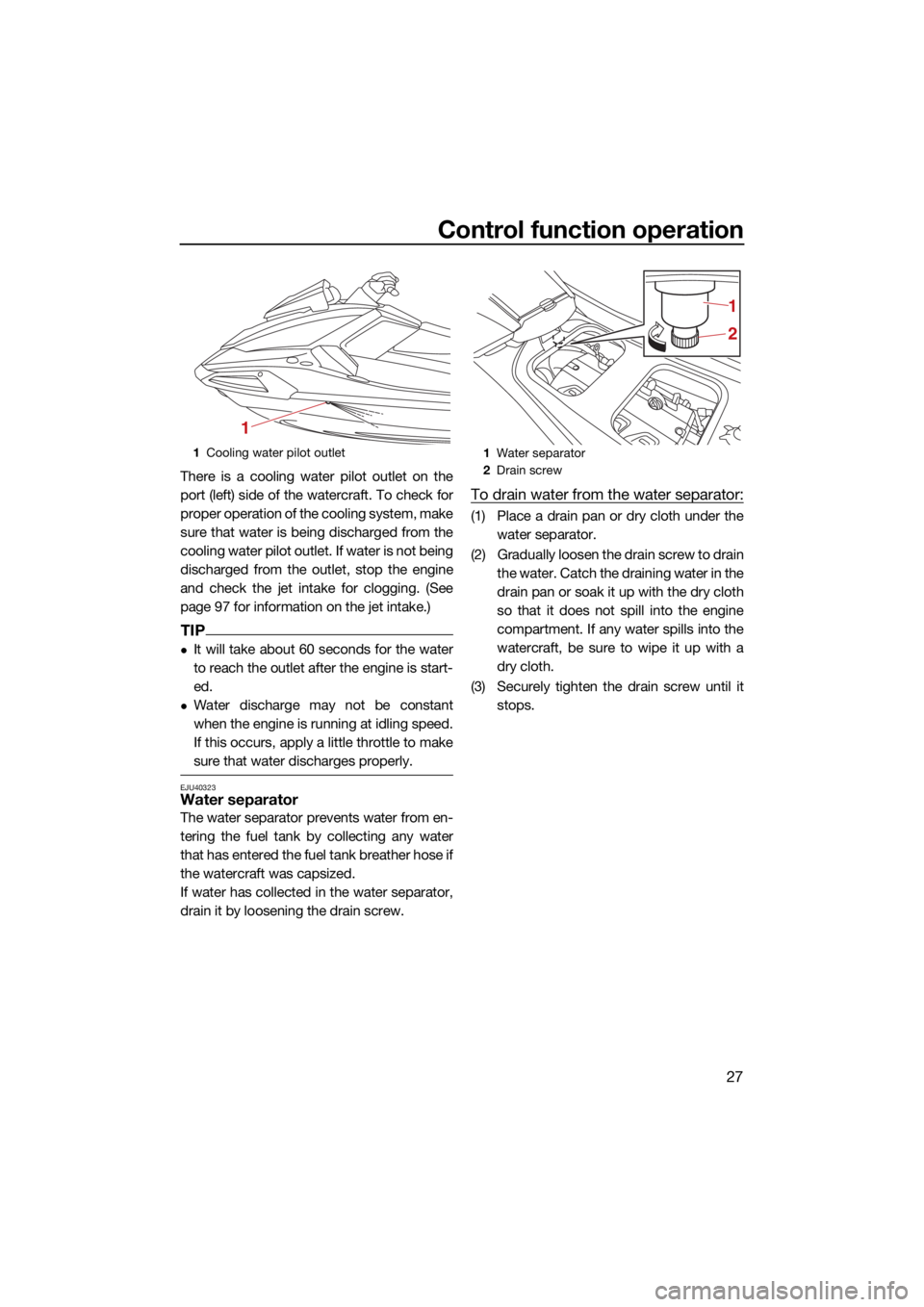
There is a cooling water pilot outlet on the
port (left) side of the watercraft. To check for
proper operation of the cooling system, make
sure that water is being discharged from the
cooling water pilot outlet. If water is not being
discharged from the outlet, stop the engine
and check the jet intake for clogging. (See
page 97 for information on the jet intake.)
TIP
It will take about 60 seconds for the water
to reach the outlet after the engine is start-
ed.
Water discharge may not be constant
when the engine is running at idling speed.
If this occurs, apply a little throttle to make
sure that water discharges properly.
EJU40323Water separator
The water separator prevents water from en-
tering the fuel tank by collecting any water
that has entered the fuel tank breather hose if
the watercraft was capsized.
If water has collected in the water separator,
drain it by loosening the drain screw.
To drain water from the water separator:
(1) Place a drain pan or dry cloth under thewater separator.
(2) Gradually loosen the drain screw to drain the water. Catch the draining water in the
drain pan or soak it up with the dry cloth
so that it does not spill into the engine
compartment. If any water spills into the
watercraft, be sure to wipe it up with a
dry cloth.
(3) Securely tighten the drain screw until it stops.
1Cooling water pilot outlet
1
1Water separator
2 Drain screw
2 1
UF4S71E0.book Page 27 Wednesday, August 4, 2021 5:18 PM
Page 63 of 112
Operation and handling requirements
55
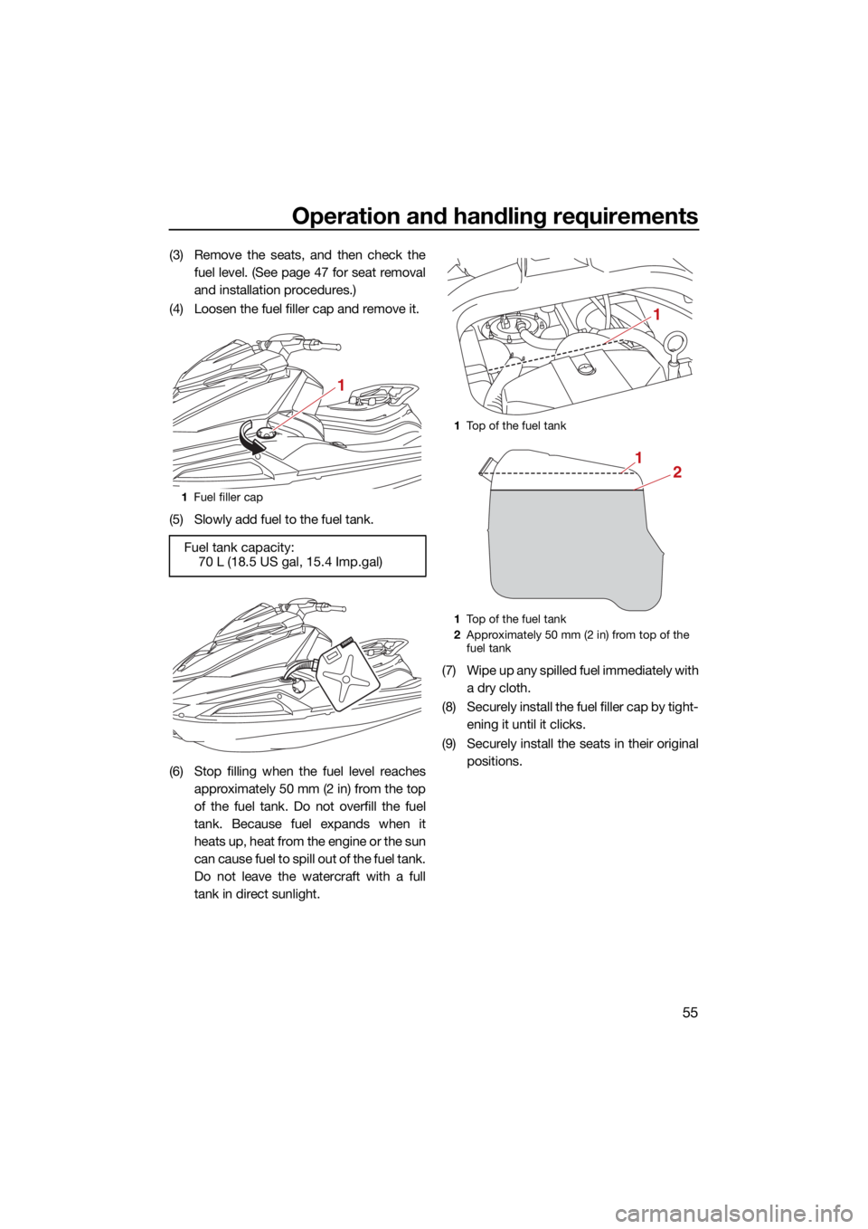
(3) Remove the seats, and then check thefuel level. (See page 47 for seat removal
and installation procedures.)
(4) Loosen the fuel filler cap and remove it.
(5) Slowly add fuel to the fuel tank.
(6) Stop filling when the fuel level reaches approximately 50 mm (2 in) from the top
of the fuel tank. Do not overfill the fuel
tank. Because fuel expands when it
heats up, heat from the engine or the sun
can cause fuel to spill out of the fuel tank.
Do not leave the watercraft with a full
tank in direct sunlight. (7) Wipe up any spilled fuel immediately with
a dry cloth.
(8) Securely install the fuel filler cap by tight- ening it until it clicks.
(9) Securely install the seats in their original positions.
1Fuel filler cap
Fuel tank capacity:
70 L (18.5 US gal, 15.4 Imp.gal)
1
1Top of the fuel tank
1 Top of the fuel tank
2 Approximately 50 mm (2 in) from top of the
fuel tank
1
21
UF4S71E0.book Page 55 Wednesday, August 4, 2021 5:18 PM
Page 71 of 112
Pre-operation checks
63
EJU32282
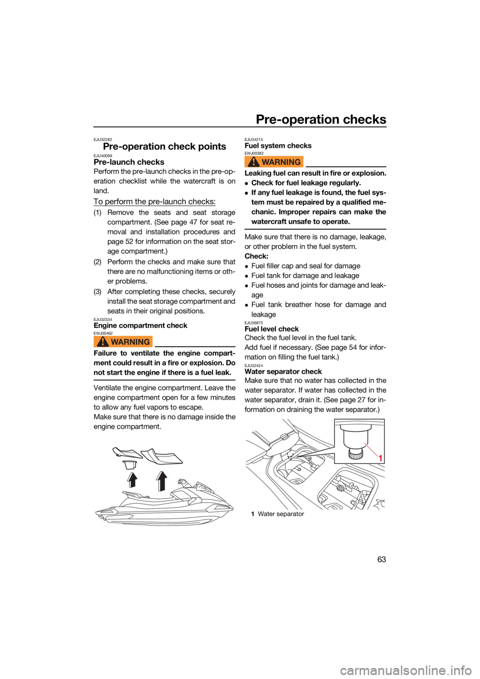
Pre-operation check pointsEJU40099Pre-launch checks
Perform the pre-launch checks in the pre-op-
eration checklist while the watercraft is on
land.
To perform the pre-launch checks:
(1) Remove the seats and seat storagecompartment. (See page 47 for seat re-
moval and installation procedures and
page 52 for information on the seat stor-
age compartment.)
(2) Perform the checks and make sure that there are no malfunctioning items or oth-
er problems.
(3) After completing these checks, securely install the seat storage compartment and
seats in their original positions.
EJU32334Engine compartment checkEWJ00462
Failure to ventilate the engine compart-
ment could result in a fire or explosion. Do
not start the engine if there is a fuel leak.
Ventilate the engine compartment. Leave the
engine compartment open for a few minutes
to allow any fuel vapors to escape.
Make sure that there is no damage inside the
engine compartment.
EJU34215Fuel system checksEWJ00382
Leaking fuel can result in fire or explosion.
Check for fuel leakage regularly.
If any fuel leakage is found, the fuel sys-
tem must be repaired by a qualified me-
chanic. Improper repairs can make the
watercraft unsafe to operate.
Make sure that there is no damage, leakage,
or other problem in the fuel system.
Check:
Fuel filler cap and seal for damage
Fuel tank for damage and leakage
Fuel hoses and joints for damage and leak-
age
Fuel tank breather hose for damage and
leakage
EJU36875Fuel level check
Check the fuel level in the fuel tank.
Add fuel if necessary. (See page 54 for infor-
mation on filling the fuel tank.)
EJU32424Water separator check
Make sure that no water has collected in the
water separator. If water has collected in the
water separator, drain it. (See page 27 for in-
formation on draining the water separator.)
1Water separator
1
UF4S71E0.book Page 63 Wednesday, August 4, 2021 5:18 PM
Page 90 of 112
Care and storage
82
EJU37148
Post-operation careEWJ00332
Always place the watercraft upright in a
horizontal position when storing it, other-
wise fuel could leak out into the engine or
engine compartment, which could create
a fire hazard.
After using the watercraft, always take it out
of the water, clean it, and store it. Leaving the
watercraft in the water for extended periods
will accelerate the rate of normal deteriora-
tion of the jet pump and hull. Marine organ-
isms and corrosion are some of the
conditions that can shorten the life of many
watercraft components.
EJU46120Flushing the cooling water passagesECJ01880
Do not run the engine over 4000 r/min on
land. Also, do not run the engine for
more than 15 seconds without supplying
water, otherwise the engine could over-
heat.
Flush the cooling water passages to
prevent them from clogging with salt,
sand, or dirt.
(1) Place the watercraft in a horizontal posi-tion.
(2) Remove the seats and seat storage compartment. (See page 47 for seat re-
moval and installation procedures and
page 52 for information on the seat stor-
age compartment.)
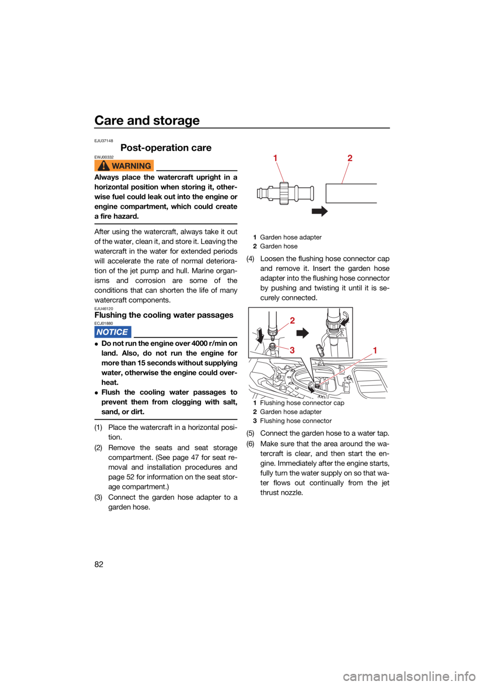
(3) Connect the garden hose adapter to a garden hose. (4) Loosen the flushing hose connector cap
and remove it. Insert the garden hose
adapter into the flushing hose connector
by pushing and twisting it until it is se-
curely connected.
(5) Connect the garden hose to a water tap.
(6) Make sure that the area around the wa- tercraft is clear, and then start the en-
gine. Immediately after the engine starts,
fully turn the water supply on so that wa-
ter flows out continually from the jet
thrust nozzle.
1Garden hose adapter
2 Garden hose
1 Flushing hose connector cap
2 Garden hose adapter
3 Flushing hose connector
12
13
2
UF4S71E0.book Page 82 Wednesday, August 4, 2021 5:18 PM
Page 97 of 112
Maintenance
89
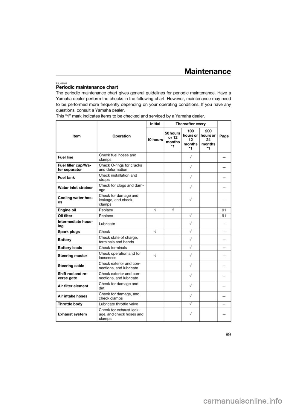
EJU43103Periodic maintenance chart
The periodic maintenance chart gives general guidelines for periodic maintenance. Have a
Yamaha dealer perform the checks in the following chart. However, maintenance may need to be performed more frequently depending on your operating conditions. If you have any
questions, consult a Yamaha dealer.
This “ √” mark indicates items to be checked and serviced by a Yamaha dealer.
Item OperationInitial Thereafter every
Page
10 hours 50 hours
or 12
months *1 100
hours or 12
months *1 200
hours or 24
months *1
Fuel line Check fuel hoses and
clamps
√
—
Fuel filler cap/Wa-
ter separator Check O-rings for cracks
and deformation
√
—
Fuel tank Check installation and
straps
√
—
Water inlet strainer Check for clogs and dam-
age
√
—
Cooling water hos-
es Check for damage and
leakage, and check
clamps
√
—
Engine oil Replace √√ 91
Oil filter Replace √91
Intermediate hous-
ing Lubricate
√—
Spark plugs Check √√ —
Battery Check state of charge,
terminals and bands
√
—
Battery leads Check terminals √—
Steering master Check operation and for
looseness
√√
—
Steering cable Check exterior and con-
nections, and lubricate
√
—
Shift rod and re-
verse gate Check exterior and con-
nections, and lubricate
√
—
Air filter element Check for damage and
dirt
√
—
Air intake hoses Check for damage, and
check clamps
√
—
Throttle body Lubricate throttle valve √—
Exhaust system Check
for exhaust leak-
age, and check hoses and
clamps √
—
UF4S71E0.book Page 89 Wednesday, August 4, 2021 5:18 PM
Page 100 of 112
Specifications
92
EJU46451
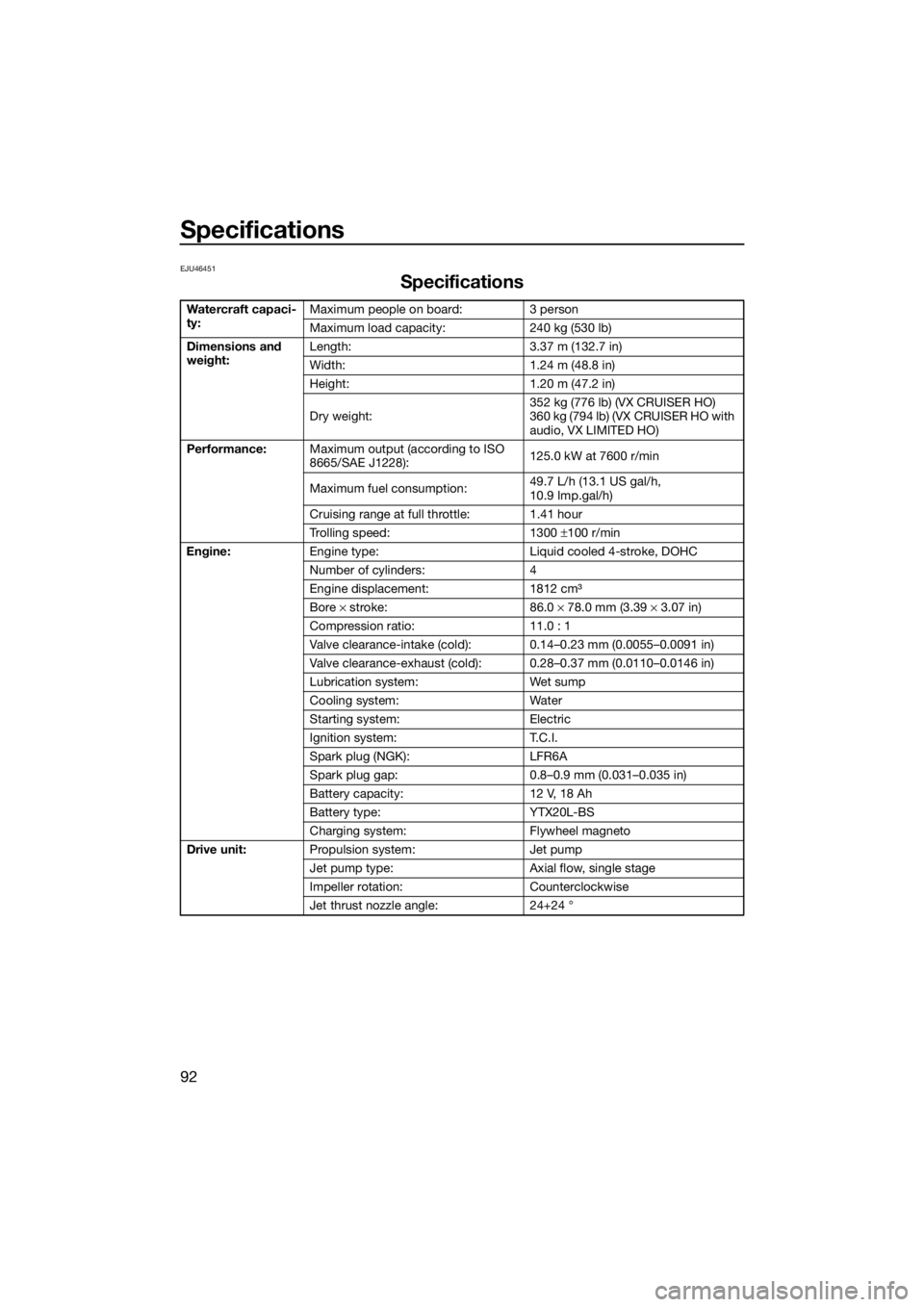
Specifications
Watercraft capaci-
ty:Maximum people on board: 3 person
Maximum load capacity: 240 kg (530 lb)
Dimensions and
weight: Length: 3.37 m (132.7 in)
Width: 1.24 m (48.8 in)
Height: 1.20 m (47.2 in)
Dry weight: 352 kg (776 lb) (VX CRUISER HO)
360 kg (794 lb) (VX CRUISER HO with
audio, VX LIMITED HO)
Performance: Maximum output (according to ISO
8665/SAE J1228): 125.0 kW at 7600 r/min
Maximum fuel consumption: 49.7 L/h (13.1 US gal/h,
10.9 Imp.gal/h)
Cruising range at full throttle: 1.41 hour
Trolling speed: 1300 ±100 r/min
Engine: Engine type: Liquid cooled 4-stroke, DOHC
Number of cylinders: 4
Engine displacement: 1812 cm³
Bore × stroke: 86.0 × 78.0 mm (3.39 × 3.07 in)
Compression ratio: 11.0 : 1
Valve clearance-intake (cold): 0.14–0.23 mm (0.0055–0.0091 in)
Valve clearance-exhaust (cold): 0.28–0.37 mm (0.0110–0.0146 in)
Lubrication system: Wet sump
Cooling system: Water
Starting system: Electric
Ignition system: T.C.I.
Spark plug (NGK): LFR6A
Spark plug gap: 0.8–0.9 mm (0.031–0.035 in)
Battery capacity: 12 V, 18 Ah
Battery type: YTX20L-BS
Charging system: Flywheel magneto
Drive unit: Propulsion system: Jet pump
Jet pump type: Axial flow, single stage
Impeller rotation: Counterclockwise
Jet thrust nozzle angle: 24+24 °
UF4S71E0.book Page 92 Wednesday, August 4, 2021 5:18 PM
Page 101 of 112
Specifications
93
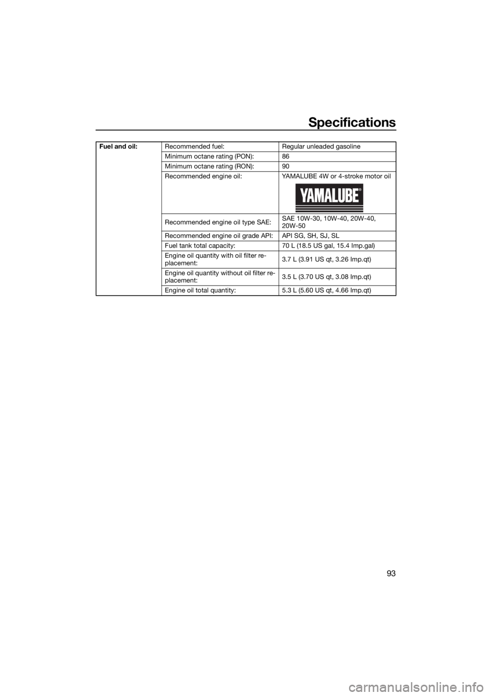
Fuel and oil:Recommended fuel: Regular unleaded gasoline
Minimum octane rating (PON): 86
Minimum octane rating (RON): 90
Recommended engine oil: YAMALUBE 4W or 4-stroke motor oil
Recommended engine oil type SAE: SAE 10W-30, 10W-40, 20W-40,
20W-50
Recommended engine oil grade API: API SG, SH, SJ, SL
Fuel tank total capacity: 70 L (18.5 US gal, 15.4 Imp.gal)
Engine oil quantity with oil filter re-
placement: 3.7 L (3.91 US qt, 3.26 Imp.qt)
Engine oil quantity without oil filter re-
placement: 3.5 L (3.70 US qt, 3.08 Imp.qt)
Engine oil total quantity: 5.3 L (5.60 US qt, 4.66 Imp.qt)
UF4S71E0.book Page 93 Wednesday, August 4, 2021 5:18 PM