ECU YAMAHA VX LIMITED HO 2022 Owners Manual
[x] Cancel search | Manufacturer: YAMAHA, Model Year: 2022, Model line: VX LIMITED HO, Model: YAMAHA VX LIMITED HO 2022Pages: 112, PDF Size: 4.8 MB
Page 7 of 112

Table of contents
General and important labels ........... 1Identification numbers .................... 1
Primary Identification (PRI-ID)
number............................................ 1
Craft Identification Number (CIN) ....... 1
Engine serial number.......................... 1
Manufactured date label .................... 2
Model information ........................... 3
Builder’s plate .................................... 3
Important labels .............................. 4
Warning labels.................................... 5
Other labels ........................................ 8
Safety information ............................. 9 Limitations on who may operate the watercraft ............................... 9
Cruising limitations ........................ 10
Operation requirements ................ 11
Recommended equipment ........... 13
Hazard information........................ 14
Watercraft characteristics ............. 14
Wakeboarding and water-skiing ... 16
Safe boating rules ......................... 17
Enjoy your watercraft responsibly ................................. 18
Description....................................... 19 Watercraft glossary ....................... 19
Location of main components ...... 20
Control function operation ............. 24 Watercraft control functions ......... 24
Yamaha Security System ................. 24
Engine start/stop switch ................. 25
Engine shut-off switch .................... 25
Throttle lever .................................... 25
RiDE lever ........................................ 26
Steering system ............................... 26
Cooling water pilot outlet ................. 26
Water separator................................ 27
Watercraft operation ...................... 28Watercraft operation functions ..... 28
Shift system ..................................... 28
Watercraft operation modes ......... 31
Reverse assist .................................. 31
T.D.E.
(thrust directional enhancer) ......... 31
No-wake mode ................................. 32
Drive control mode ........................... 33
Cruise assist ..................................... 35
Instrument operation ...................... 37 Multifunction information center ... 37
Operation buttons ............................ 37
Display.............................................. 37
Home screen ................................... 39
Information screen .......................... 39
Drive control mode screen .............. 40
Setting menu screen ....................... 40
Engine lock screen .......................... 41
Warning function .............................. 42
Audio system (equipped models) ..................... 44
Audio control .................................... 44
Accessory outlet ........................... 45
USB charger ................................. 46
Equipment operation ...................... 47 Equipment..................................... 47
Seats ................................................ 47
Handgrip........................................... 48
Reboarding grip................................ 48
Reboarding step ............................... 48
Bow eye............................................ 49
Stern eyes ........................................ 49
Cleat ................................................. 49
Pull-up cleats ................................... 50
Storage compartments .................... 50
Fire extinguisher holder and cover ... 53
UF4S71E0.book Page 1 Wednesday, August 4, 2021 5:18 PM
Page 32 of 112

Control function operation
24
EJU31027
Watercraft control functionsEJU45091Yamaha Security System
The Yamaha Security System functions to
help prevent unauthorized use or theft of the
watercraft. The lock and unlock modes of the
security system can be selected using the
engine lock screen of the multifunction infor-
mation center. The engine cannot be started
if the lock mode of the security system is se-
lected. The engine can only be started if the
unlock mode is selected.
TIP
The Yamaha Security System setting can
only be selected while the engine is stopped.
EJU45870Yamaha Security System settingThe Yamaha Security System setting can be
confirmed by the lock or unlock mode indica-
tor on the multifunction information center.
To select the lock or unlock mode of the
Yamaha Security System:
(1) Stop the engine.
TIP
The multifunction information center is turned
on, even if the engine start/stop switch is also
pushed briefly.
(2) Select the lock or unlock mode indicator
on the multifunction information center.
(3) Input each digit of the 4-digit PIN, and then push the “OK” button of the touch-
pad control.
TIP
The default setting for the PIN is “1234”. The
PIN can also be changed. (See page 40 for in-
formation on changing the PIN.)
(4) To select the lock mode of the YamahaSecurity System, select “ON”. To select
the unlock mode, select “OFF”.
(5) The beeper sounds once when the lock mode of the Yamaha Security System is
selected, and two times when the unlock
mode is selected.
1Lock mode indicator
2 Unlock mode indicator
2
1
Enter PIN
* * * *123
456
789
0
Engine Lock
ON
OFF
UF4S71E0.book Page 24 Wednesday, August 4, 2021 5:18 PM
Page 33 of 112
Control function operation
25
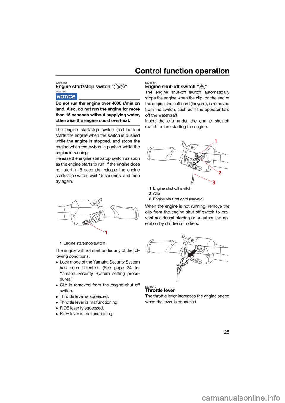
EJU46112Engine start/stop switch “ / ”ECJ01311
Do not run the engine over 4000 r/min on
land. Also, do not run the engine for more
than 15 seconds without supplying water,
otherwise the engine could overheat.
The engine start/stop switch (red button)
starts the engine when the switch is pushed
while the engine is stopped, and stops the
engine when the switch is pushed while the
engine is running.
Release the engine start/stop switch as soon
as the engine starts to run. If the engine does
not start in 5 seconds, release the engine
start/stop switch, wait 15 seconds, and then
try again.
The engine will not start under any of the fol-
lowing conditions:
Lock mode of the Yamaha Security System
has been selected. (See page 24 for
Yamaha Security System setting proce- dures.)
Clip is removed from the engine shut-off
switch.
Throttle lever is squeezed.
Throttle lever is malfunctioning.
RiDE lever is squeezed.
RiDE lever is malfunctioning.
EJU31164Engine shut-off switch “ ”
The engine shut-off switch automatically
stops the engine when the clip, on the end of
the engine shut-off cord (lanyard), is removed
from the switch, such as if the operator falls
off the watercraft.
Insert the clip under the engine shut-off
switch before starting the engine.
When the engine is not running, remove the
clip from the engine shut-off switch to pre-
vent accidental starting or unauthorized op-
eration by children or others.
EJU31212Throttle lever
The throttle lever increases the engine speed
when the lever is squeezed.
1 Engine start/stop switch
1
1Engine shut-off switch
2 Clip
3 Engine shut-off cord (lanyard)
1
2
3
UF4S71E0.book Page 25 Wednesday, August 4, 2021 5:18 PM
Page 35 of 112
Control function operation
27
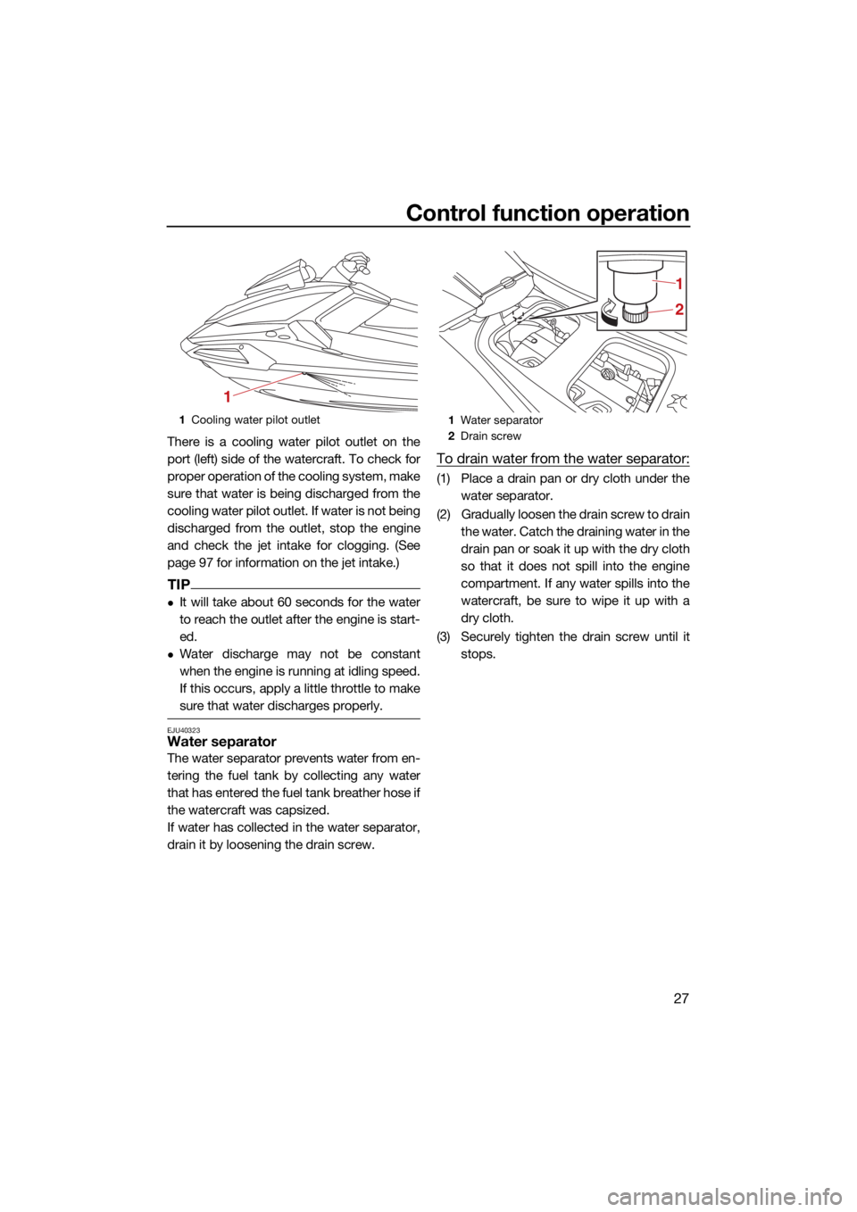
There is a cooling water pilot outlet on the
port (left) side of the watercraft. To check for
proper operation of the cooling system, make
sure that water is being discharged from the
cooling water pilot outlet. If water is not being
discharged from the outlet, stop the engine
and check the jet intake for clogging. (See
page 97 for information on the jet intake.)
TIP
It will take about 60 seconds for the water
to reach the outlet after the engine is start-
ed.
Water discharge may not be constant
when the engine is running at idling speed.
If this occurs, apply a little throttle to make
sure that water discharges properly.
EJU40323Water separator
The water separator prevents water from en-
tering the fuel tank by collecting any water
that has entered the fuel tank breather hose if
the watercraft was capsized.
If water has collected in the water separator,
drain it by loosening the drain screw.
To drain water from the water separator:
(1) Place a drain pan or dry cloth under thewater separator.
(2) Gradually loosen the drain screw to drain the water. Catch the draining water in the
drain pan or soak it up with the dry cloth
so that it does not spill into the engine
compartment. If any water spills into the
watercraft, be sure to wipe it up with a
dry cloth.
(3) Securely tighten the drain screw until it stops.
1Cooling water pilot outlet
1
1Water separator
2 Drain screw
2 1
UF4S71E0.book Page 27 Wednesday, August 4, 2021 5:18 PM
Page 49 of 112
Instrument operation
41
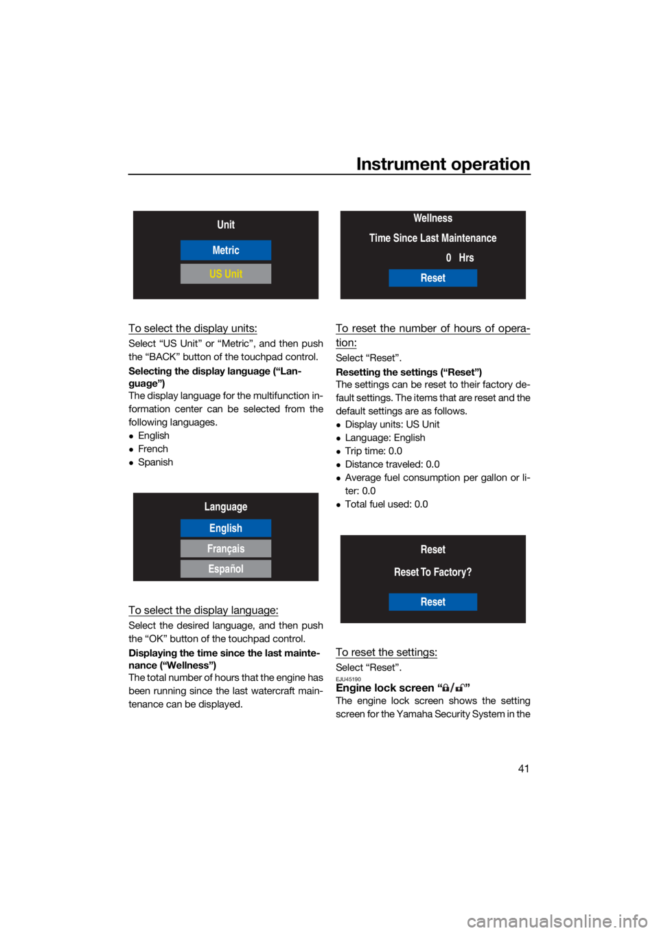
To select the display units:
Select “US Unit” or “Metric”, and then push
the “BACK” button of the touchpad control.
Selecting the display language (“Lan-
guage”)
The display language for the multifunction in-
formation center can be selected from the
following languages.
English
French
Spanish
To select the display language:
Select the desired language, and then push
the “OK” button of the touchpad control.
Displaying the time since the last mainte-
nance (“Wellness”)
The total number of hours that the engine has
been running since the last watercraft main-
tenance can be displayed.
To reset the number of hours of opera-
tion:
Select “Reset”.
Resetting the settings (“Reset”)
The settings can be reset to their factory de-
fault settings. The items that are reset and the
default settings are as follows.
Display units: US Unit
Language: English
Trip time: 0.0
Distance traveled: 0.0
Average fuel consumption per gallon or li-
ter: 0.0
Total fuel used: 0.0
To reset the settings:
Select “Reset”.EJU45190Engine lock screen “ ”
The engine lock screen shows the setting
screen for the Yamaha Security System in the
Unit
Metric
US Unit
Language
English
Français
Español
Wellness
Time Since Last Maintenance 0Hrs
Reset
Reset
Reset To Factory?
Reset
UF4S71E0.book Page 41 Wednesday, August 4, 2021 5:18 PM
Page 55 of 112
Equipment operation
47
EJU40336
EquipmentEJU31045Seats
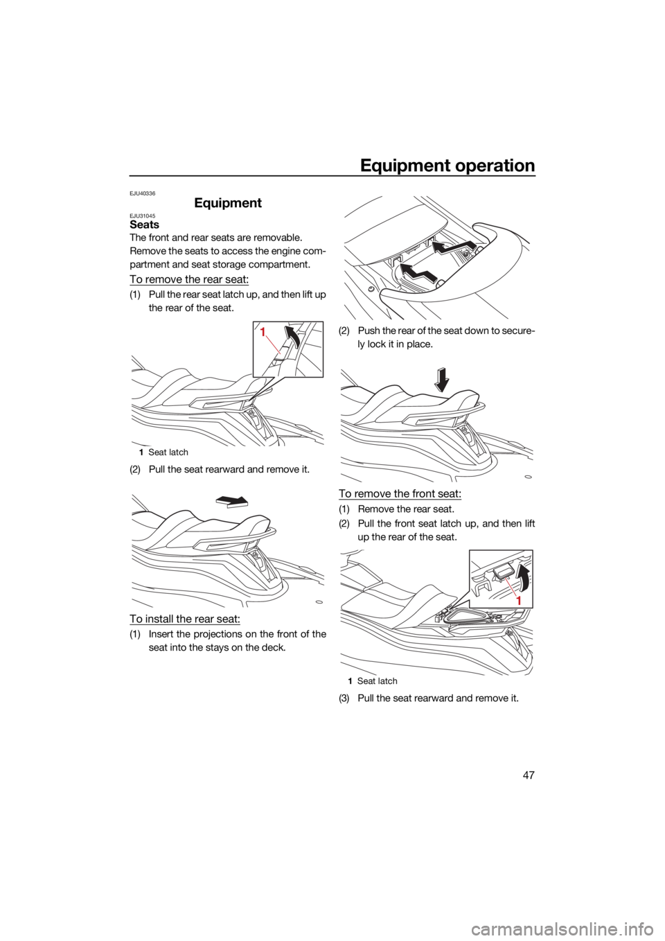
The front and rear seats are removable.
Remove the seats to access the engine com-
partment and seat storage compartment.
To remove the rear seat:
(1) Pull the rear seat latch up, and then lift upthe rear of the seat.
(2) Pull the seat rearward and remove it.
To install the rear seat:
(1) Insert the projections on the front of the seat into the stays on the deck. (2) Push the rear of the seat down to secure-
ly lock it in place.
To remove the front seat:
(1) Remove the rear seat.
(2) Pull the front seat latch up, and then liftup the rear of the seat.
(3) Pull the seat rearward and remove it.
1 Seat latch
1
1Seat latch
1
UF4S71E0.book Page 47 Wednesday, August 4, 2021 5:18 PM
Page 56 of 112
Equipment operation
48
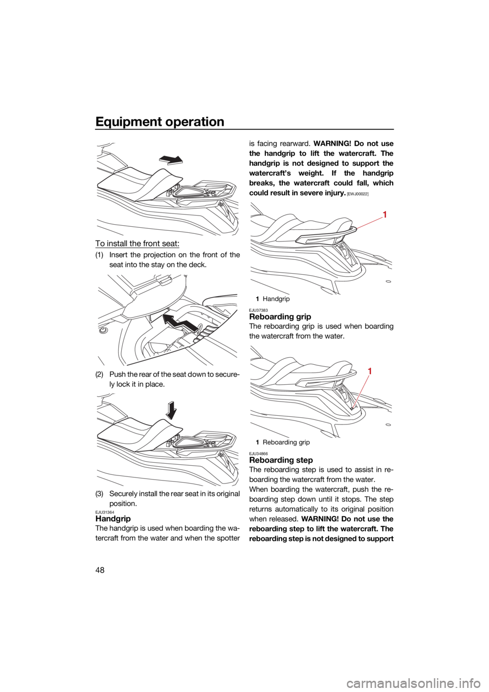
To install the front seat:
(1) Insert the projection on the front of theseat into the stay on the deck.
(2) Push the rear of the seat down to secure- ly lock it in place.
(3) Securely install the rear seat in its original position.
EJU31364Handgrip
The handgrip is used when boarding the wa-
tercraft from the water and when the spotter is facing rearward.
WARNING! Do not use
the handgrip to lift the watercraft. The
handgrip is not designed to support the
watercraft’s weight. If the handgrip
breaks, the watercraft could fall, which
could result in severe injury.
[EWJ00022]
EJU37383
Reboarding grip
The reboarding grip is used when boarding
the watercraft from the water.
EJU34866Reboarding step
The reboarding step is used to assist in re-
boarding the watercraft from the water.
When boarding the watercraft, push the re-
boarding step down until it stops. The step
returns automatically to its original position
when released. WARNING! Do not use the
reboarding step to lift the watercraft. The
reboarding step is not designed to support
1 Handgrip
1 Reboarding grip
1
1
UF4S71E0.book Page 48 Wednesday, August 4, 2021 5:18 PM
Page 58 of 112
Equipment operation
50
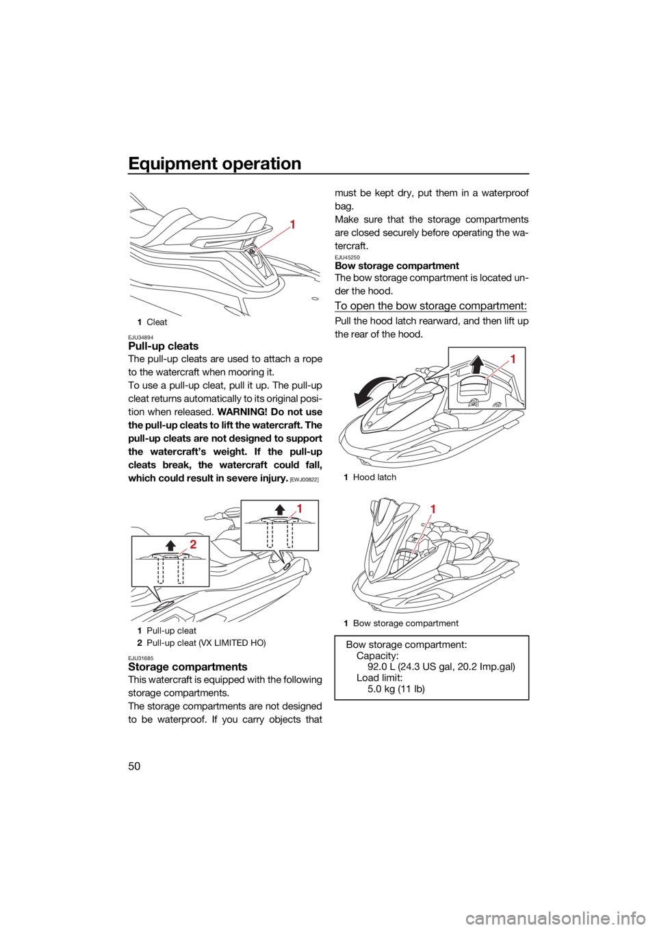
EJU34894Pull-up cleats
The pull-up cleats are used to attach a rope
to the watercraft when mooring it.
To use a pull-up cleat, pull it up. The pull-up
cleat returns automatically to its original posi-
tion when released. WARNING! Do not use
the pull-up cleats to lift the watercraft. The
pull-up cleats are not designed to support
the watercraft’s weight. If the pull-up
cleats break, the watercraft could fall,
which could result in severe injury.
[EWJ00822]
EJU31685
Storage compartments
This watercraft is equipped with the following
storage compartments.
The storage compartments are not designed
to be waterproof. If you carry objects that must be kept dry, put them in a waterproof
bag.
Make sure that the storage compartments
are closed securely before operating the wa-
tercraft.
EJU45250Bow storage compartment
The bow storage compartment is located un-
der the hood.
To open the bow storage compartment:
Pull the hood latch rearward, and then lift up
the rear of the hood.1
Cleat
1 Pull-up cleat
2 Pull-up cleat (VX LIMITED HO)
1
2
1
1Hood latch
1 Bow storage compartment
Bow storage compartment:
Capacity: 92.0 L (24.3 US gal, 20.2 Imp.gal)
Load limit: 5.0 kg (11 lb)
1
1
UF4S71E0.book Page 50 Wednesday, August 4, 2021 5:18 PM
Page 59 of 112
Equipment operation
51
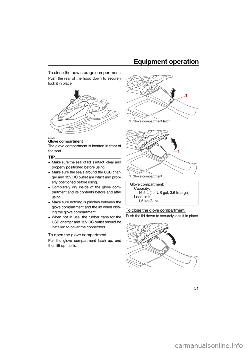
To close the bow storage compartment:
Push the rear of the hood down to securely
lock it in place.
EJU46211Glove compartment
The glove compartment is located in front of
the seat.
TIP
Make sure the seal of lid is intact, clear and
properly positioned before using.
Make sure the seals around the USB char-
ger and 12V DC outlet are intact and prop-
erly positioned before using.
Completely dry inside of the glove com-
partment and its contents before and after
using.
Make sure nothing is pinches between the
glove compartment and the lid when clos-
ing the glove compartment.
When not in use, the rubber caps for the
USB charger and 12V DC outlet should be
installed to cover the connectors.
To open the glove compartment:
Pull the glove compartment latch up, and
then lift up the lid.
To close the glove compartment:
Push the lid down to securely lock it in place.
1Glove compartment latch
1 Glove compartment
Glove compartment:
Capacity: 16.5 L (4.4 US gal, 3.6 Imp.gal)
Load limit: 1.5 kg (3 lb)
1
1
UF4S71E0.book Page 51 Wednesday, August 4, 2021 5:18 PM
Page 60 of 112
Equipment operation
52
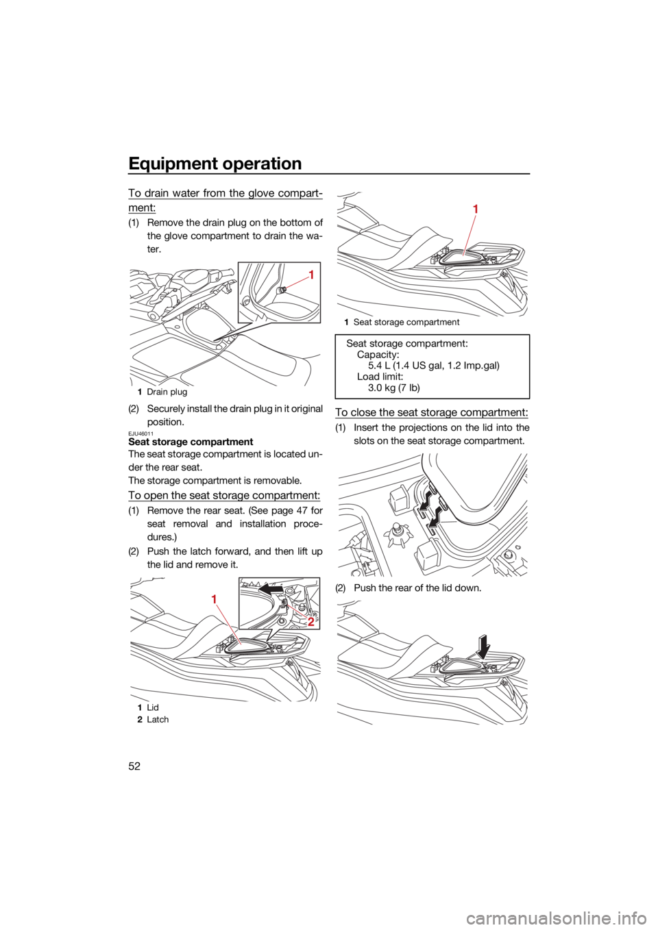
To drain water from the glove compart-
ment:
(1) Remove the drain plug on the bottom ofthe glove compartment to drain the wa-
ter.
(2) Securely install the drain plug in it original position.
EJU46011Seat storage compartment
The seat storage compartment is located un-
der the rear seat.
The storage compartment is removable.
To open the seat storage compartment:
(1) Remove the rear seat. (See page 47 forseat removal and installation proce-
dures.)
(2) Push the latch forward, and then lift up the lid and remove it.
To close the seat storage compartment:
(1) Insert the projections on the lid into theslots on the seat storage compartment.
(2) Push the rear of the lid down.
1 Drain plug
1 Lid
2 Latch
1
2
1
1
Seat storage compartment
Seat storage compartment:
Capacity: 5.4 L (1.4 US gal, 1.2 Imp.gal)
Load limit:
3.0 kg (7 lb)
1
UF4S71E0.book Page 52 Wednesday, August 4, 2021 5:18 PM