ESP YAMAHA VX110 2005 Owner's Manual
[x] Cancel search | Manufacturer: YAMAHA, Model Year: 2005, Model line: VX110, Model: YAMAHA VX110 2005Pages: 347, PDF Size: 14.17 MB
Page 40 of 347

2-19
ESPECCABLE AND HOSE ROUTING
12
Ð
Ò
Ó
Õ
Î
ÍÌ
È
É
È
É
Ñ
Ô
3
4
5678
4
B
O
P
5
N
C
D
A09H-H
EFGH
I
P
G
G-G
A
BD
F C
E
JJ
M
C
F
I
I
E
DB
A
A
ÏÐ
H
H
G
G
JK
0
Q
L
Ê
Ë
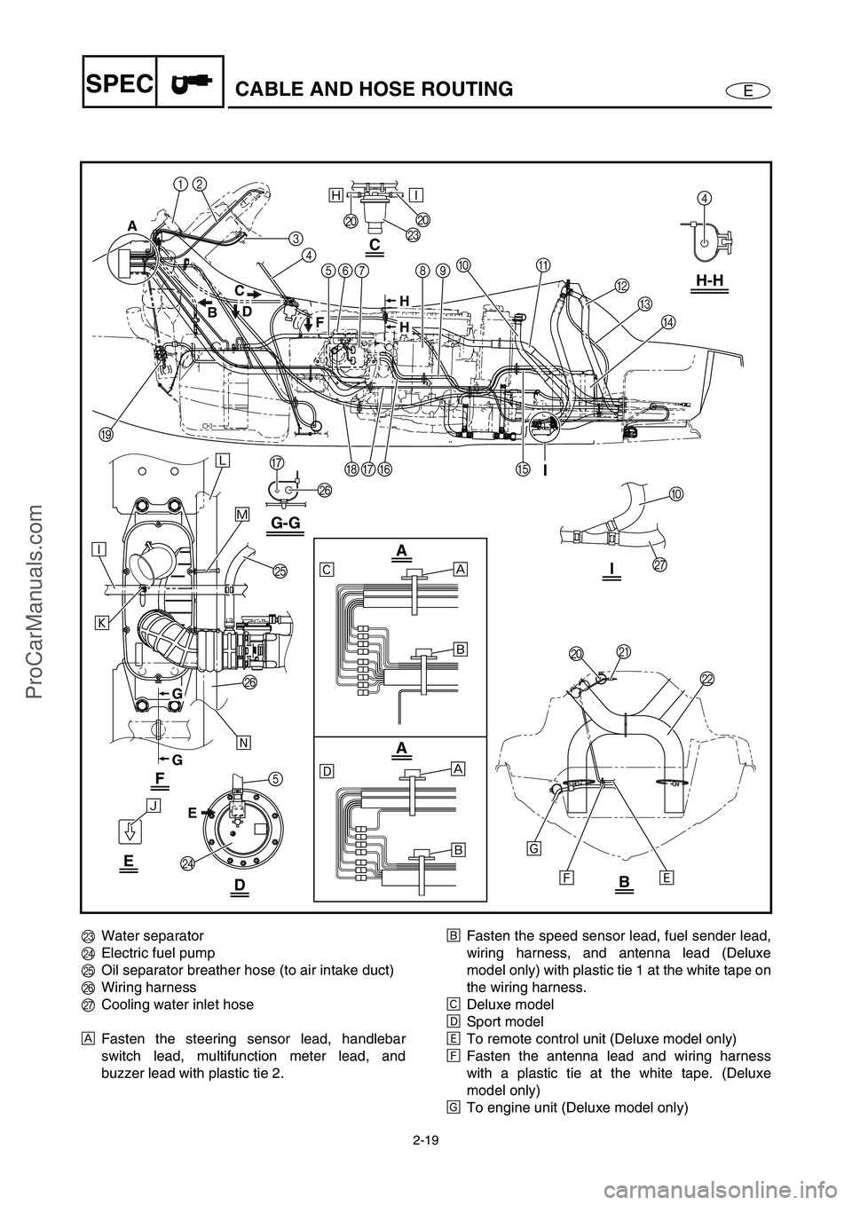
MWater separator
NElectric fuel pump
OOil separator breather hose (to air intake duct)
PWiring harness
QCooling water inlet hose
ÈFasten the steering sensor lead, handlebar
switch lead, multifunction meter lead, and
buzzer lead with plastic tie 2.ÉFasten the speed sensor lead, fuel sender lead,
wiring harness, and antenna lead (Deluxe
model only) with plastic tie 1 at the white tape on
the wiring harness.
ÊDeluxe model
ËSport model
ÌTo remote control unit (Deluxe model only)
ÍFasten the antenna lead and wiring harness
with a plastic tie at the white tape. (Deluxe
model only)
ÎTo engine unit (Deluxe model only)
ProCarManuals.com
Page 41 of 347

2-20
ESPECCABLE AND HOSE ROUTING
12
Ð
Ò
Ó
Õ
Î
ÍÌ
È
É
È
É
Ñ
Ô
3
4
5678
4
B
O
P
5
N
C
D
A09H-H
EFGH
I
P
G
G-G
A
BD
F C
E
JJ
M
C
F
I
I
E
DB
A
A
ÏÐ
H
H
G
G
JK
0
Q
L
Ê
Ë
ÏTo ventilation socket
ÐTo fuel tank
ÑPoint the arrow on the cover toward the fuel
tank.
ÒFasten the fuel hose with a plastic tie.
ÓTo fuse box
ÔFasten the wiring harness with a plastic tie at
the white tape.
ÕTo ECM
ProCarManuals.com
Page 42 of 347

2-21
ESPECCABLE AND HOSE ROUTING
A
B
C
D
2
4
2
5
6
7
8
3
2
28
Ñ
Ê
Ó Ò
Ê
ÊÍ
É
Ë
F-FE-E
2
1222
2
2
Õ
ÈÐ
Ô
ÎÌÏ
F
F
E
E
D C
A
B
2
1Cooling water inlet hose
2Cooling water hose
3Cooling water outlet hose
4Flushing hose
5Cylinder head breather hose
6Oil separator breather hose (to oil tank)
7Oil separator breather hose (to air intake duct)
8Cooling water pilot outlet hoseÈTo install the cooling water outlet hose, align the
white paint mark on the cooling water hose with
the projection of the hose joint.
ÉTo transom plate
ÊFasten the cooling water outlet hose with a plas-
tic tie.
Ë25–45 mm (0.98–1.77 in)
ÌFasten the oil separator breather (to oil tank)
hose and cooling water hose with a holder.
ProCarManuals.com
Page 43 of 347

2-22
ESPECCABLE AND HOSE ROUTING
A
B
C
D
2
4
2
5
6
7
8
3
2
28
Ñ
Ê
Ó Ò
Ê
ÊÍ
É
Ë
F-FE-E
2
1222
2
2
Õ
ÈÐ
Ô
ÎÌÏ
F
F
E
E
D C
A
B
2
ÍFasten the oil separator breather hose (to air
intake duct) and cooling water hose with a
holder.
ÎFace the ends of the hose clamp towards the
starboard (right) side of the watercraft.
ÏInsert the cooling water hose to the paint mark.
ÐTo install the cooling water hose, align the white
paint mark on the cooling water hose with the
arrow mark of the hose joint.ÑInstall the cooling water hose with the white
paint mark facing up.
ÒTo cooling water pilot outlet
ÓFace the ends of the hose clamp towards the
bow.
ÔInstall the hose onto the cooling water pipe until
the pipe reaches the curve in the hose.
ÕInsert the plastic tie completely into the hole in
the boss on the cylinder block.
ProCarManuals.com
Page 44 of 347

2-23
ESPECCABLE AND HOSE ROUTING
13
90A
C B
88
4567
2
E
D
F
È
É
Í
Ê
Ë
Ì A-A
AA
Î
1Oil separator breather hose (to air intake duct)
2Wiring harness
3Ignition coil lead #1
4Ignition coil lead #2
5Ignition coil lead #3
6Ignition coil lead #4
7Cam position sensor
8Ignition coil
9ECM
0Rectifier/regulator
AOil pressure switch couplerBThermoswitch (exhaust) coupler
CGround lead plate
DWiring harness
EThermoswitch (exhaust) lead
FOil pressure switch lead
ÈFasten the oil separator breather hose (to air
intake duct) at the paint mark with a holder.
É15–25 mm (0.59–0.98 in)
ÊTo fuse box
ËTo multifunction meter
ProCarManuals.com
Page 45 of 347

2-24
ESPECCABLE AND HOSE ROUTING
13
90A
C B
88
4567
2
E
D
F
È
É
Í
Ê
Ë
Ì A-A
AA
Î
ÌTo generator
ÍFasten the thermoswitch (exhaust) lead at the
protective sleeve, the oil pressure switch lead at
the corrugated tube, and the wiring harness at
the tape on the harness with a plastic tie.
Î60–80 mm (2.36–3.15 in)
ProCarManuals.com
Page 46 of 347

2-25
ESPECCABLE AND HOSE ROUTING
D-D
A-A
B-B
0
8
5
C-C
9
5 Ú
Ù
É
È
Ð
DD
5
6
A
A
1
2
7
34
Î
Ó ÒÌÑÑÌÑ
Ì
Ì
Ë Ë
Ê
Ø×Ö Ô
Õ
Í
Ï
C
CB
B
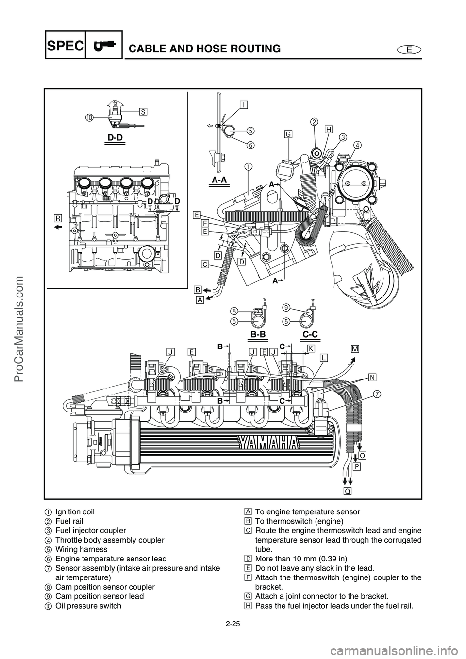
1Ignition coil
2Fuel rail
3Fuel injector coupler
4Throttle body assembly coupler
5Wiring harness
6Engine temperature sensor lead
7Sensor assembly (intake air pressure and intake
air temperature)
8Cam position sensor coupler
9Cam position sensor lead
0Oil pressure switchÈTo engine temperature sensor
ÉTo thermoswitch (engine)
ÊRoute the engine thermoswitch lead and engine
temperature sensor lead through the corrugated
tube.
ËMore than 10 mm (0.39 in)
ÌDo not leave any slack in the lead.
ÍAttach the thermoswitch (engine) coupler to the
bracket.
ÎAttach a joint connector to the bracket.
ÏPass the fuel injector leads under the fuel rail.
ProCarManuals.com
Page 47 of 347

2-26
ESPECCABLE AND HOSE ROUTING
D-D
A-A
B-B
0
8
5
C-C
9
5 Ú
Ù
É
È
Ð
DD
5
6
A
A
1
2
7
34
Î
Ó ÒÌÑÑÌÑ
Ì
Ì
Ë Ë
Ê
Ø×Ö Ô
Õ
Í
Ï
C
CB
B
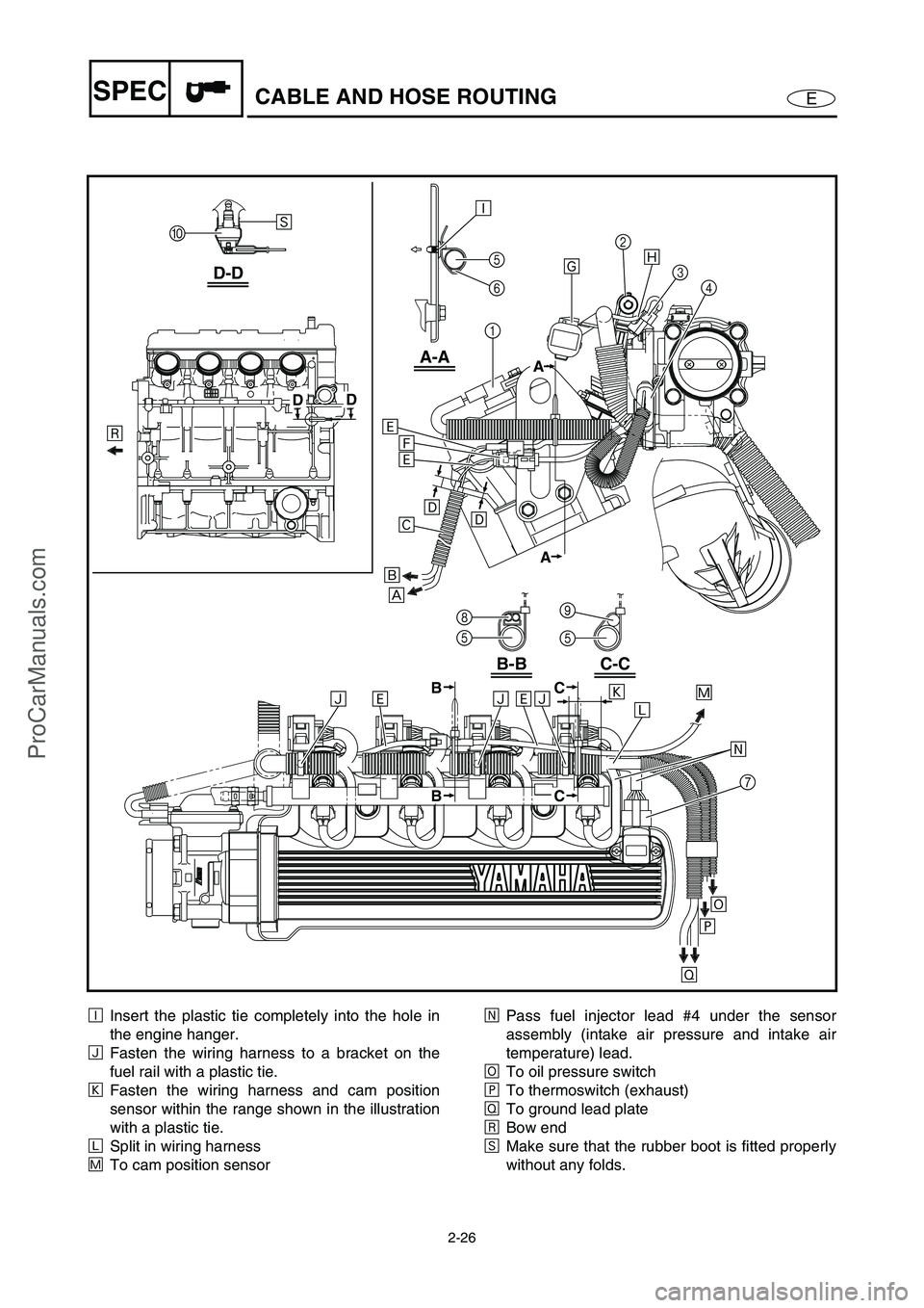
ÐInsert the plastic tie completely into the hole in
the engine hanger.
ÑFasten the wiring harness to a bracket on the
fuel rail with a plastic tie.
ÒFasten the wiring harness and cam position
sensor within the range shown in the illustration
with a plastic tie.
ÓSplit in wiring harness
ÔTo cam position sensorÕPass fuel injector lead #4 under the sensor
assembly (intake air pressure and intake air
temperature) lead.
ÖTo oil pressure switch
×To thermoswitch (exhaust)
ØTo ground lead plate
ÙBow end
ÚMake sure that the rubber boot is fitted properly
without any folds.
ProCarManuals.com
Page 105 of 347

5-6
EPOWRENGINE UNIT
7. Install:
Ignition coils
T R..
Ignition coils bolt:
7.6 N m (0.76 kgf m, 5.5 ft lb)
LOCTITE 572
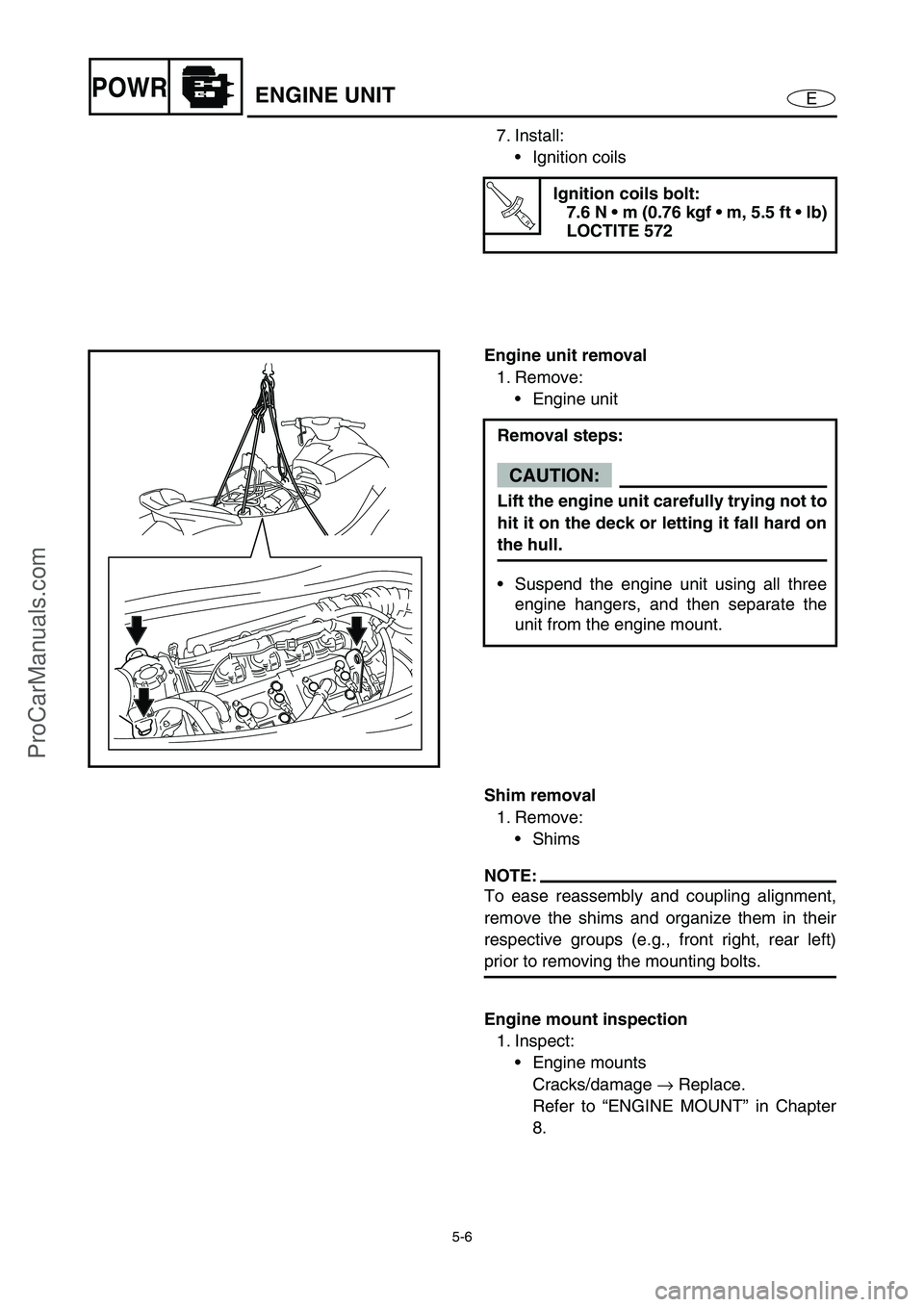
Engine unit removal
1. Remove:
Engine unit
Removal steps:
CAUTION:
Lift the engine unit carefully trying not to
hit it on the deck or letting it fall hard on
the hull.
Suspend the engine unit using all three
engine hangers, and then separate the
unit from the engine mount.
Shim removal
1. Remove:
Shims
NOTE:
To ease reassembly and coupling alignment,
remove the shims and organize them in their
respective groups (e.g., front right, rear left)
prior to removing the mounting bolts.
Engine mount inspection
1. Inspect:
Engine mounts
Cracks/damage →
Replace.
Refer to “ENGINE MOUNT” in Chapter
8.
ProCarManuals.com
Page 188 of 347

5-89
EPOWRCONNECTING RODS AND PISTONS
For example, if the connecting rod “P1” and the
crankshaft web “P
1” numbers are “5” and “1”
respectively, then the bearing size for “P
1” is:
Bearing size of P
1:
“P
1” (connecting rod) –
“P
1” (crankshaft web)
5 – 1 = 4 (green)
BEARING COLOR CODE
1brown
2 black
3blue
4 green5 G
P4P3P2P1
Connecting rod and piston installation
The following procedure applies to all of the
pistons and connecting rods.
1. Install:
Oil ring
2nd ring
Top ring
NOTE:
Be sure to install the piston rings so that the
manufacturer’s marks or numbers face up.
2. Install:
Piston 1
Connecting rod 2
Piston pin 3
Piston pin clips 4
NOTE:
Apply engine oil onto the piston pin.
When installing the connecting rod to the pis-
ton, make sure that the “Y” mark a
on the
connecting rod faces towards the left when
the exhaust valve recesses b
on the piston
face upward. Refer to the illustration.
Reinstall each piston into its original cylinder
(numbering order starting from the front: #1
to #4).
ProCarManuals.com