steering YAMAHA VX110 2005 Owner's Manual
[x] Cancel search | Manufacturer: YAMAHA, Model Year: 2005, Model line: VX110, Model: YAMAHA VX110 2005Pages: 347, PDF Size: 14.17 MB
Page 300 of 347

8-7
E
HULL
HOODHANDLEBAR
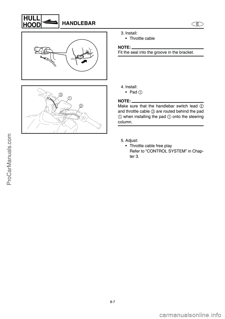
3. Install:
Throttle cable
NOTE:
Fit the seal into the groove in the bracket.
4. Install:
Pad 1
NOTE:
Make sure that the handlebar switch lead 2
and throttle cable 3
are routed behind the pad
1
when installing the pad 1
onto the steering
column.
5. Adjust:
Throttle cable free play
Refer to “CONTROL SYSTEM” in Chap-
ter 3.
ProCarManuals.com
Page 313 of 347

8-20
E
HULL
HOODSTEERING COLUMN
STEERING COLUMN
EXPLODED DIAGRAM
REMOVAL AND INSTALLATION CHART
Step Procedure/Part name Q’ty Service points
STEERING COLUMN REMOVAL
Follow the left “Step” for removal.
Engine hatch cover Refer to “ENGINE HATCH COVER”.
Steering cable end Refer to “REMOTE CONTROL CABLES
AND SPEED SENSOR LEAD”.
1Bolt 1
2 Steering arm 1
3 Joint ball 1
4Bolt 4
5 Steering column assembly 1
Reverse the removal steps for installation.
5
4
2
3 1
6.9 N • m (0.69 kgf m, 5.0 ft Ib)
8 × 30 mm
17 N m (1.7 kgf m, 12 ft Ib)
LT
572
LT
LT
242
LT
8 × 18 mm
20 N m (2.0 kgf m, 14 ft Ib)
ProCarManuals.com
Page 314 of 347

8-21
E
HULL
HOODSTEERING COLUMN
EXPLODED DIAGRAM
REMOVAL AND INSTALLATION CHART
Step Procedure/Part name Q’ty Service points
STEERING COLUMN
DISASSEMBLYFollow the left “Step” for disassembly.
1 Steering column 1
2 Seal rubber 1
3Bolt 4
4 Steering sensor 1
5Bolt 3
6 Spacer 1
7Buzzer 1
8 Steering housing assembly 1
Reverse the disassembly steps for
assembly.
6
LT
572
LT
LT
572
LT
3
4 1
8
27 5
7
8 × 25 mm
16 N • m (1.6 kgf • m, 12 ft • Ib)
ProCarManuals.com
Page 315 of 347

8-22
E
HULL
HOODSTEERING COLUMN
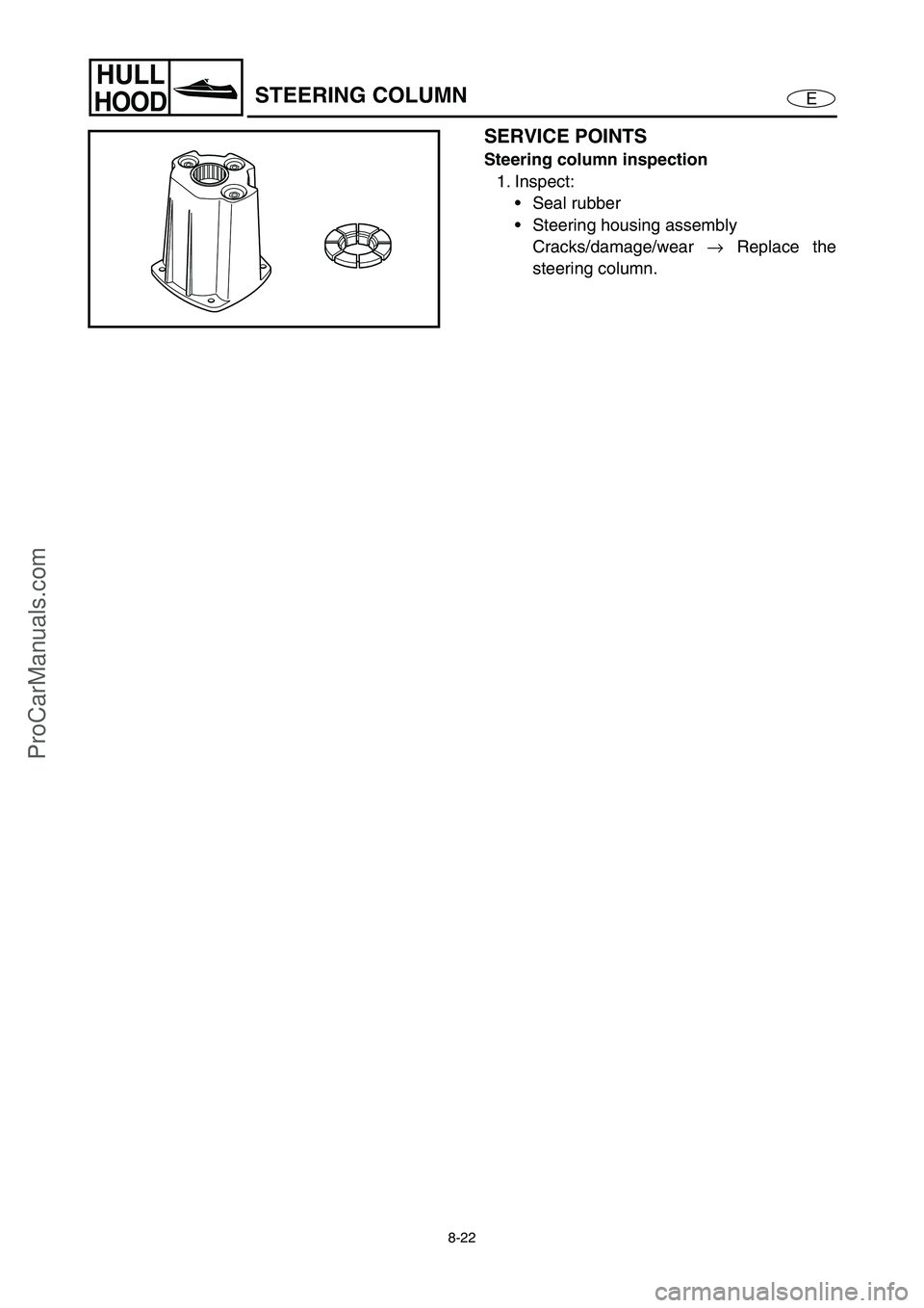
SERVICE POINTS
Steering column inspection
1. Inspect:
Seal rubber
Steering housing assembly
Cracks/damage/wear →
Replace the
steering column.
ProCarManuals.com
Page 316 of 347

8-23
E
HULL
HOOD
REMOTE CONTROL CABLES AND
SPEED SENSOR LEAD
REMOTE CONTROL CABLES AND SPEED SENSOR LEAD
EXPLODED DIAGRAM
REMOVAL AND INSTALLATION CHART
Step Procedure/Part name Q’ty Service points
REMOTE CONTROL CABLES
AND SPEED SENSOR LEAD
REMOVALFollow the left “Step” for removal.
Service lid 1 Refer to “FRONT HOOD”.
Seat assembly Refer to “SEAT AND HAND GRIP”.
Engine hatch cover Refer to “ENGINE HATCH COVER”.
Shift lever Refer to “SHIFT LEVER (DELUXE MODEL
ONLY)”.
1 Steering cable end 1
2Bolt 1
3Bracket 1
ProCarManuals.com
Page 317 of 347

8-24
E
HULL
HOOD
REMOTE CONTROL CABLES AND
SPEED SENSOR LEAD
EXPLODED DIAGRAM
Step Procedure/Part name Q’ty Service points
4Nut 1
5 Steering cable 1
6 Seal 1
7 Speed sensor coupler 1
8Nut 1
9Cap 1
10 Screw 4
11 Speed sensor 1
12 Bolt 2 Deluxe model only
13 Shift cable holder 1 Deluxe model only
ProCarManuals.com
Page 319 of 347

8-26
E
HULL
HOOD
REMOTE CONTROL CABLES AND
SPEED SENSOR LEAD
SERVICE POINTS
WARNING
When routing the cables, do not grasp the
cable by the outer crimped sheath or steel
end. This could deform or loosen the cable
end due to extreme angles and or pressure.
Always hold the cables by the outer cover
below the crimp.
If a cable becomes damaged replace it.
Never attempt to repair a damaged cable.
Remote control cables inspection
1. Inspect:
Steering cable
Shift cable (Deluxe model only)
Frays/kinks/rough movement →
Replace.
Steering cable (jet pump end) installation
1. Install:
Steering cable
WARNING
The steering cable must be screwed in at
least 8 mm (0.31 in).
Steering cable set length
a
(jet pump end):
14.5 mm (0.57 in)
Steering cable stopper installation
1. Install:
Steering cable stopper
WARNING
Be sure to the steering cable stopper into
the groove in the outer cable as shown in
the illustration.
ProCarManuals.com
Page 337 of 347

9-4
E
TRBL
ANLS
TROUBLE ANALYSIS
TROUBLE ANALYSIS
NOTE:
Before consulting the “TROUBLE ANALYSIS CHART,” check the following items.
1. Check that the battery is charged and that its specified gravity is within specification.
2. Check that there are no incorrect wiring connections.
3. Check that all wiring connections are properly secured and that they are not rusty.
4. Check that the engine shut-off cord (lanyard) is connect to the engine shut-off switch.
5. Check that fuel is reaching the fuel rail.
TROUBLE ANALYSIS CHART
Trouble mode Check elements
ENGINE WILL NOT START
HARD STARTING
ROUGH IDLING
HIGH IDLING
ENGINE STALLS
POOR ACCELERATION
ENGINE WILL NOT STOP
POOR PERFORMANCE
LIMITED ENGINE SPEED
OVERHEATING
LOW OIL PRESSURE
LOOSE STEERING
BILGE INCREASE
IRREGULAR WARNING INDICATION
POOR BATTERY CHARGING
Relative partReference
chapter
FUEL SYSTEM
Fuel tank 4
Fuel tank breather hose 4
Fuel hose 4
Fuel filter 4
Fuel pump 4
Fuel rail 4
Fuel injectors 4
Trolling speed 3
Air filter 3
ProCarManuals.com
Page 338 of 347

9-5
E
TRBL
ANLS
TROUBLE ANALYSIS
POWER UNIT
Compression 5
Cylinder head gaskets 5
Cylinder block 5
Crankcase 5
Piston rings 5
Pistons 5
Bearings 5
Valve(s) and valve seat(s) 5
Valve clearance adjusting
pad(s)3
Camshaft(s) 5
Timing chain 5
Oil pump 5
Engine oil 3
Oil filter 3
Oil pressure switch 7
Bearing housing 5
Drive couplings 5
Rubber coupling 5
Pilot water hose 5
Water hose 5
Water passage 5 Trouble mode Check elements
ENGINE WILL NOT START
HARD STARTING
ROUGH IDLING
HIGH IDLING
ENGINE STALLS
POOR ACCELERATION
ENGINE WILL NOT STOP
POOR PERFORMANCE
LIMITED ENGINE SPEED
OVERHEATING
LOW OIL PRESSURE
LOOSE STEERING
BILGE INCREASE
IRREGULAR WARNING INDICATION
POOR BATTERY CHARGING
Relative partReference
chapter
ProCarManuals.com
Page 339 of 347

9-6
E
TRBL
ANLS
TROUBLE ANALYSIS
JET PUMP UNIT
Duct 6
Impeller 6
Intake grate 6
Bearings 6
Water inlet hose 6
Bilge hose 6
Bilge strainer 3
Bilge hose joint 6
ELECTRICAL
Ignition system, fuel control system
Pickup coils 7
ECM 7
Ignition coils 7
Slant detection switch 7
Engine stop switch 7
Engine shut-off switch 7
Spark plugs 3
Main and fuel pump relay 7
Electronic control throttle
valve relay7
Thermoswitch 7
Sensor assembly 7
Engine temperature
sensor7
Throttle body assembly
(throttle position sensor)7
Accelerator position
sensor7
Cam position sensor 7 Trouble mode Check elements
ENGINE WILL NOT START
HARD STARTING
ROUGH IDLING
HIGH IDLING
ENGINE STALLS
POOR ACCELERATION
ENGINE WILL NOT STOP
POOR PERFORMANCE
LIMITED ENGINE SPEED
OVERHEATING
LOW OIL PRESSURE
LOOSE STEERING
BILGE INCREASE
IRREGULAR WARNING INDICATION
POOR BATTERY CHARGING
Relative partReference
chapter
ProCarManuals.com