ad blue YAMAHA VX110 2005 Service Manual
[x] Cancel search | Manufacturer: YAMAHA, Model Year: 2005, Model line: VX110, Model: YAMAHA VX110 2005Pages: 347, PDF Size: 14.17 MB
Page 6 of 347
E
A50001-1-4
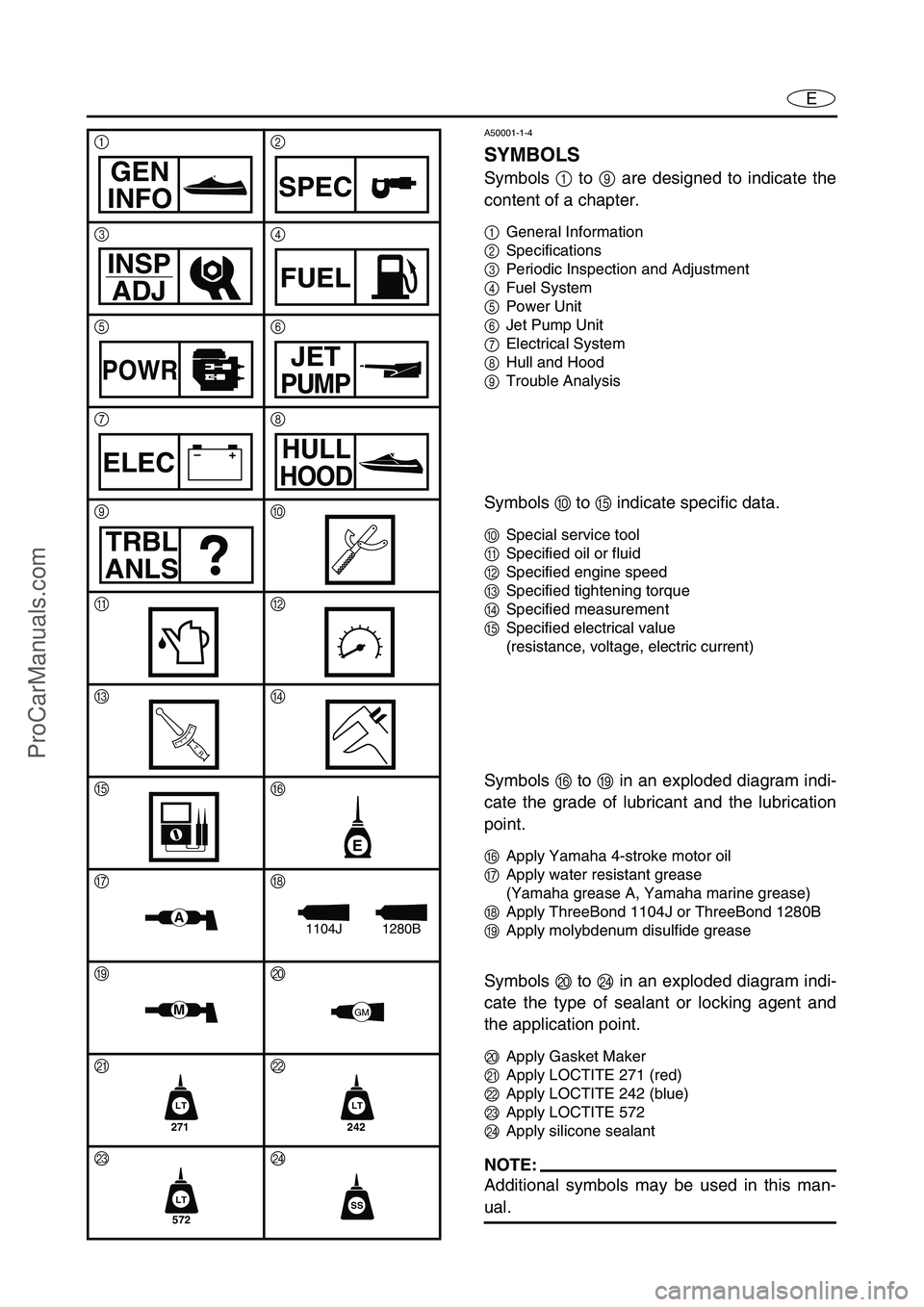
SYMBOLS
Symbols 1 to 9 are designed to indicate the
content of a chapter.
1General Information
2Specifications
3Periodic Inspection and Adjustment
4Fuel System
5Power Unit
6Jet Pump Unit
7Electrical System
8Hull and Hood
9Trouble Analysis
Symbols 0 to E indicate specific data.
0Special service tool
ASpecified oil or fluid
BSpecified engine speed
CSpecified tightening torque
DSpecified measurement
ESpecified electrical value
(resistance, voltage, electric current)
Symbols F to I in an exploded diagram indi-
cate the grade of lubricant and the lubrication
point.
FApply Yamaha 4-stroke motor oil
GApply water resistant grease
(Yamaha grease A, Yamaha marine grease)
HApply ThreeBond 1104J or ThreeBond 1280B
IApply molybdenum disulfide grease
Symbols J to N in an exploded diagram indi-
cate the type of sealant or locking agent and
the application point.
JApply Gasket Maker
KApply LOCTITE 271 (red)
LApply LOCTITE 242 (blue)
MApply LOCTITE 572
NApply silicone sealant
NOTE:
Additional symbols may be used in this man-
ual.
12
34
56
78
90
AB
CD
EF
GH
IJ
KL
MN
GEN
INFOSPEC
INSP
ADJFUEL
POWRJET
PUMP
–+ELECHULL
HOOD
TRBL
ANLS
T R..
E
A1280B1104J
MGM
271
LT
242
LT
572
LTSS
ProCarManuals.com
Page 26 of 347

2-5
ESPECMAINTENANCE SPECIFICATIONS
Piston pins
Outside diameter mm (in) 16.991–17.000 (0.6689–0.6693)
Wear limit mm (in) 16.986 (0.6687)
Piston ring
Top ring
Type Barrel
Dimension (B ×
T) mm (in) 0.90 ×
2.75 (0.04 ×
0.11)
End gap (installed) mm (in) 0.32–0.44 (0.0126–0.0173)
Ring groove clearance mm (in) 0.030–0.065 (0.0012–0.0026)
2nd ring
Type Taper
Dimensions (B ×
T) mm (in) 0.80 ×
2.80 (0.03 ×
0.11)
End gap (installed) mm (in) 0.43–0.58 (0.0169–0.0228)
Ring groove clearance mm (in) 0.020–0.055 (0.0008–0.0022)
Oil ring
Dimensions
(B ×
T)mm (in) 1.50 ×
2.60 (0.06 ×
0.10)
End gap (installed) mm (in) 0.10–0.35 (0.0039–0.0138)
Ring groove clearance mm (in) 0.040–0.160 (0.0016–0.0063)
Connecting rod
Big end oil clearance mm (in) 0.016–0.040 (0.0006–0.0016)
Bearing color code 1. Brown 2. Black 3. Blue 4. Green
Small end inside diameter mm (in) 17.005–17.018 (0.6695–0.6700)
Crankshaft
Crank width A mm (in) 304.8–306.0 (12.00–12.05)
Deflection limit B mm (in) 0.03 (0.0012)
Crankshaft journal oil clearance mm (in) 0.004–0.028 (0.0002–0.0011)
Bearing color code 3. Red/Red 4. Red/Brown 5. Red/Black
6. Red/Blue 7. Red/Green
Throttle body
Type/quantity IM-230/1
Manufacturer Mikuni
ID mark 6D300
Trolling speed r/min 1,550–1,750 Item UnitModel
VX110 Sport VX110 Deluxe
T
B
B
T
B
T
BBB
A
ProCarManuals.com
Page 146 of 347
5-47
EPOWRCAMSHAFTS
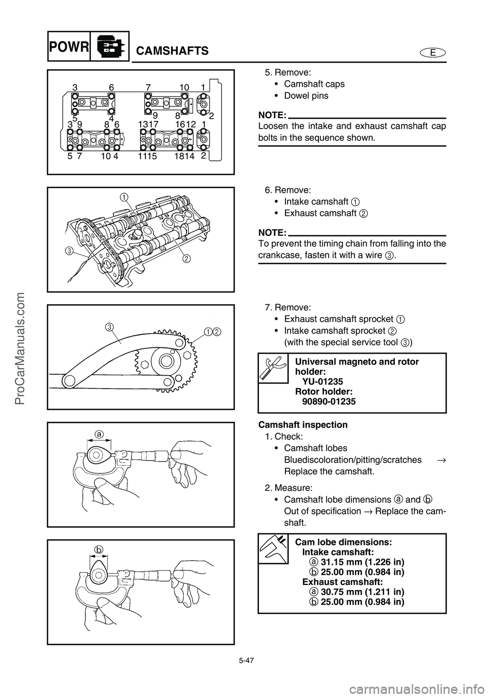
5. Remove:
Camshaft caps
Dowel pins
NOTE:
Loosen the intake and exhaust camshaft cap
bolts in the sequence shown.
1 10 7 6 3
2
14 18 15 11 4 10 7 52 8 9
4 5
1 12 16 17 13
6 8 9 3
6. Remove:
Intake camshaft 1
Exhaust camshaft 2
NOTE:
To prevent the timing chain from falling into the
crankcase, fasten it with a wire 3
.
7. Remove:
Exhaust camshaft sprocket 1
Intake camshaft sprocket 2
(with the special service tool 3
)
Universal magneto and rotor
holder:
YU-01235
Rotor holder:
90890-01235
Camshaft inspection
1. Check:
Camshaft lobes
Bluediscoloration/pitting/scratches →
Replace the camshaft.
2. Measure:
Camshaft lobe dimensions a
and b
Out of specification →
Replace the cam-
shaft.
Cam lobe dimensions:
Intake camshaft:
a 31.15 mm (1.226 in)
b 25.00 mm (0.984 in)
Exhaust camshaft:
a 30.75 mm (1.211 in)
b 25.00 mm (0.984 in)
ProCarManuals.com
Page 165 of 347
5-66
EPOWRVALVES AND VALVE SPRINGS
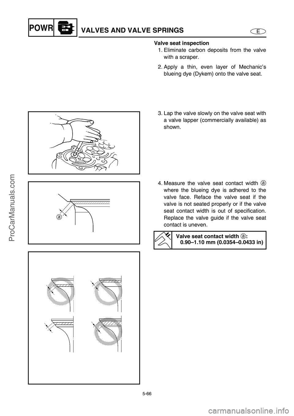
Valve seat inspection
1. Eliminate carbon deposits from the valve
with a scraper.
2. Apply a thin, even layer of Mechanic’s
blueing dye (Dykem) onto the valve seat.
3. Lap the valve slowly on the valve seat with
a valve lapper (commercially available) as
shown.
4. Measure the valve seat contact width a
where the blueing dye is adhered to the
valve face. Reface the valve seat if the
valve is not seated properly or if the valve
seat contact width is out of specification.
Replace the valve guide if the valve seat
contact is uneven.
Valve seat contact width
a:
0.90–1.10 mm (0.0354–0.0433 in)
ProCarManuals.com
Page 185 of 347
5-86
EPOWRCONNECTING RODS AND PISTONS
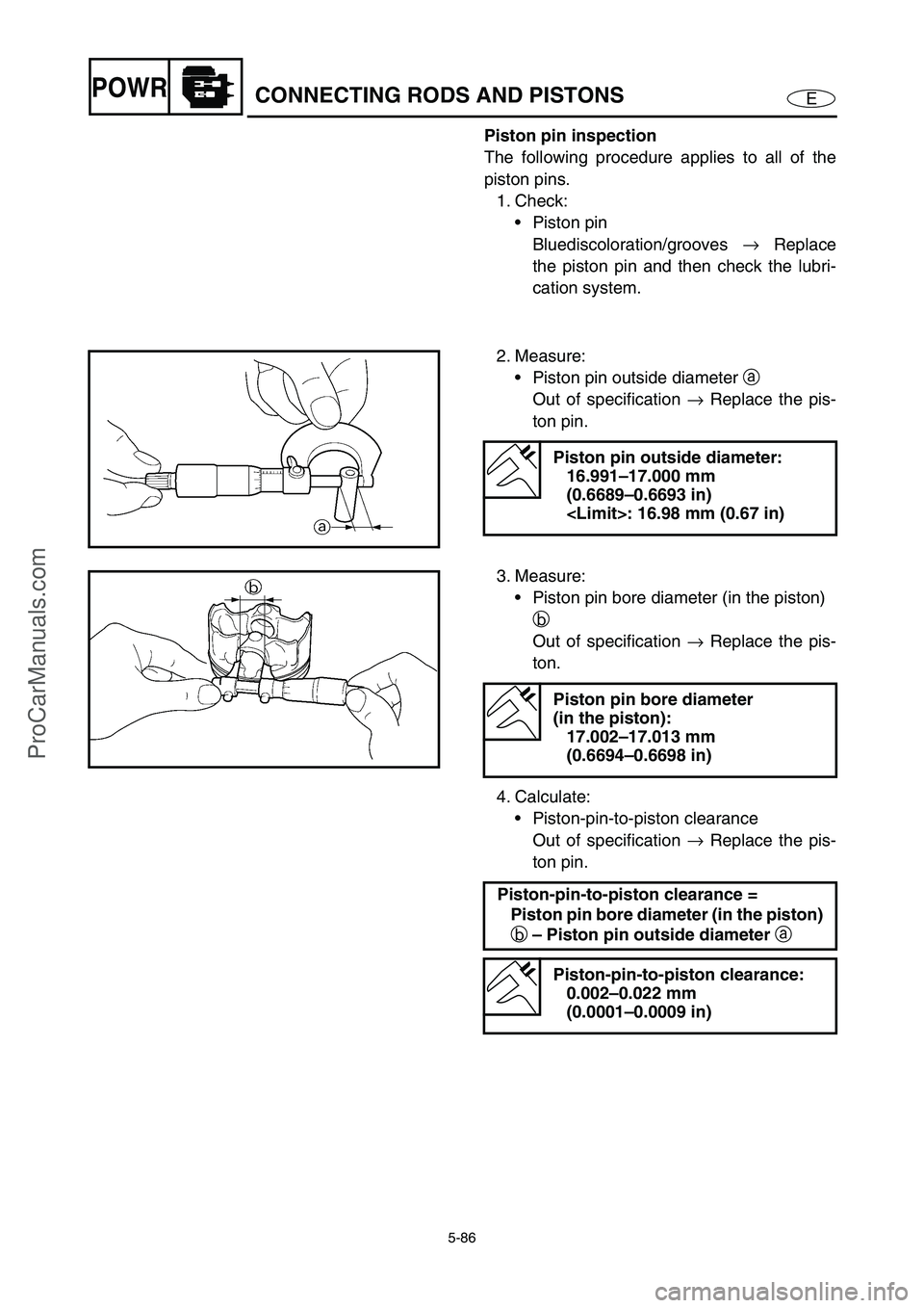
Piston pin inspection
The following procedure applies to all of the
piston pins.
1. Check:
Piston pin
Bluediscoloration/grooves →
Replace
the piston pin and then check the lubri-
cation system.
2. Measure:
Piston pin outside diameter a
Out of specification →
Replace the pis-
ton pin.
Piston pin outside diameter:
16.991–17.000 mm
(0.6689–0.6693 in)
3. Measure:
Piston pin bore diameter (in the piston)
b
Out of specification →
Replace the pis-
ton.
4. Calculate:
Piston-pin-to-piston clearance
Out of specification →
Replace the pis-
ton pin.
Piston pin bore diameter
(in the piston):
17.002–17.013 mm
(0.6694–0.6698 in)
Piston-pin-to-piston clearance =
Piston pin bore diameter (in the piston)
b – Piston pin outside diameter
a
Piston-pin-to-piston clearance:
0.002–0.022 mm
(0.0001–0.0009 in)
ProCarManuals.com
Page 188 of 347

5-89
EPOWRCONNECTING RODS AND PISTONS
For example, if the connecting rod “P1” and the
crankshaft web “P
1” numbers are “5” and “1”
respectively, then the bearing size for “P
1” is:
Bearing size of P
1:
“P
1” (connecting rod) –
“P
1” (crankshaft web)
5 – 1 = 4 (green)
BEARING COLOR CODE
1brown
2 black
3blue
4 green5 G
P4P3P2P1
Connecting rod and piston installation
The following procedure applies to all of the
pistons and connecting rods.
1. Install:
Oil ring
2nd ring
Top ring
NOTE:
Be sure to install the piston rings so that the
manufacturer’s marks or numbers face up.
2. Install:
Piston 1
Connecting rod 2
Piston pin 3
Piston pin clips 4
NOTE:
Apply engine oil onto the piston pin.
When installing the connecting rod to the pis-
ton, make sure that the “Y” mark a
on the
connecting rod faces towards the left when
the exhaust valve recesses b
on the piston
face upward. Refer to the illustration.
Reinstall each piston into its original cylinder
(numbering order starting from the front: #1
to #4).
ProCarManuals.com
Page 195 of 347

5-96
EPOWRCRANKSHAFT
Tighten the bolts to specification in the
order of the numbers on the crankcase.
Refer to “Crankcase assembly”—
“CRANKCASE”.
Remove the lower crankcase and the
crankshaft journal lower bearings.
Measure the compressed Plastigauge
width c
on each crankshaft journal.
If the crankshaft journal oil clearance is
out of specification, select replacement
crankshaft journal bearings.
c
4. Select:
Crankshaft journal bearings (J
1–J5)
NOTE:
The numbers stamped into the crankshaft
web and the numbers stamped into the lower
crankcase are used to determine the
replacement crankshaft journal bearing
sizes.
“J
1–J5” refer to the bearings shown in the
crankshaft illustration.
If “J
1–J5” are the same, use the same size
for all of the bearings.
For example, if the crankcase “J
1” and crank-
shaft web “J
1” numbers are “8” and “2” respec-
tively, then the bearing size for “J
1” is:
Bearing size of J
1:
“J
1” (crankcase) – “J1” (crankshaft web)
– 1
8 – 2 – 1 = 5 (Red/black)
BEARING COLOR CODE
3 Red/red
4Red/brown
5 Red/black
6 Red/blue
7Red/green
J5J4J3J2J1
J1J2J3J4J5
J5J4J3J2J1
ProCarManuals.com
Page 240 of 347
7-13
E
–+ELECIGNITION SYSTEM
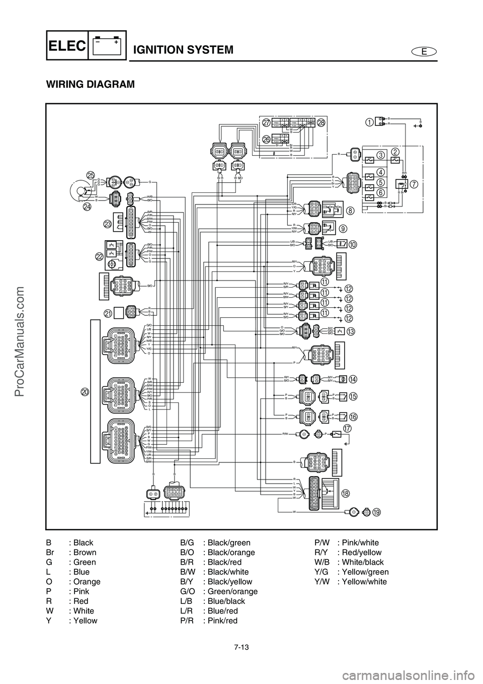
WIRING DIAGRAM
10A
10A
3A
30A20A
WBrBRFREE
PUSHBWFREE
PUSH
Br BrFREE
PUSH
BW
W
BrBrBrBrR
W
B/W
B/O
B/O
B/O
B/R
P/R
P/R
W/B
P/W
P/W
B/O
L/B
B/WB/R
B/OP/W
P/R
W
W
WLR
Y
G
O
O
W
GG
BW
GG
O
OLG
W
Y
W
G/O
W/BR/Y
Y/G
BL
PBWP/W
B/GB/Y
Y/WL/RB/RB/W
B
B
BBP
P
P
BBP
RR
BBR
R/Y
B/OL/BB/OL/B
B/G
G/OB/OG/O
P/W
B/OB/YB/YR/Y
R/Y
R/Y
R/YB/YR/Y
R/Y
B/O
B/RR/Y
R/Y
R/YY/W
Y/GL/R
Y
P
P
O
O R
R
R
BB
BrRB/O
BBr
B/W
Y BrL R B
R
GB
R/YBBr
4
0 98
B
B B
B
H
I JK LM NOQ
PR
3
5
67 2 1
A
A A
A
C
D
E
F
G
B: Black
Br : Brown
G: Green
L: Blue
O : Orange
P: Pink
R: Red
W: White
Y : YellowB/G : Black/green
B/O : Black/orange
B/R : Black/red
B/W : Black/white
B/Y : Black/yellow
G/O : Green/orange
L/B : Blue/black
L/R : Blue/red
P/R : Pink/redP/W : Pink/white
R/Y : Red/yellow
W/B : White/black
Y/G : Yellow/green
Y/W : Yellow/white
ProCarManuals.com
Page 247 of 347

7-20
E
–+ELECIGNITION SYSTEM
THERMOSWITCH (ENGINE)
1. Check:
Thermoswitch (engine) continuity
(at the specified temperature)
Out of specification →
Replace.
1 No continuity
È Temperature
2 Continuity
É Time
NOTE:
The thermoswitch (engine) connector is blue.
Thermoswitch (engine) continuity
temperature:
a 84–90 °C (183–194 °F)
b 70–84 °C (158–183 °F)
Checking steps:
Suspend the thermoswitch (engine) in a
container filled with water.
Place a thermometer in the water.
Slowly heat the water.
Measure the continuity when the speci-
fied temperature is reached.
ProCarManuals.com
Page 257 of 347
7-30
E
–+ELEC
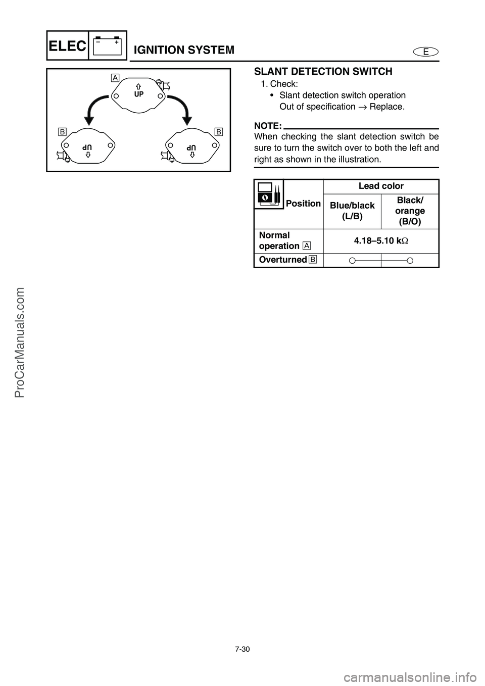
SLANT DETECTION SWITCH
1. Check:
Slant detection switch operation
Out of specification →
Replace.
NOTE:
When checking the slant detection switch be
sure to turn the switch over to both the left and
right as shown in the illustration.
PositionLead color
Blue/black
(L/B)Black/
orange
(B/O)
Normal
operation
È 4.18–5.10 k
Ω
Overturned
É
UP
UPUP
È
É É
IGNITION SYSTEM
ProCarManuals.com