key YAMAHA VX110 2005 Service Manual
[x] Cancel search | Manufacturer: YAMAHA, Model Year: 2005, Model line: VX110, Model: YAMAHA VX110 2005Pages: 347, PDF Size: 14.17 MB
Page 4 of 347

E
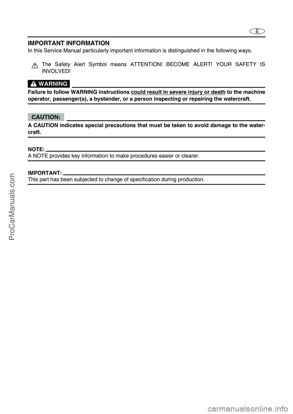
IMPORTANT INFORMATION
In this Service Manual particularly important information is distinguished in the following ways.
The Safety Alert Symbol means ATTENTION! BECOME ALERT! YOUR SAFETY IS
INVOLVED!
WARNING
Failure to follow WARNING instructions could result in severe injury or death to the machine
operator, passenger(s), a bystander, or a person inspecting or repairing the watercraft.
CAUTION:
A CAUTION indicates special precautions that must be taken to avoid damage to the water-
craft.
NOTE:
A NOTE provides key information to make procedures easier or clearer.
IMPORTANT:
This part has been subjected to change of specification during production.
ProCarManuals.com
Page 134 of 347

5-35
EPOWRGENERATOR AND STARTER MOTOR
EXPLODED DIAGRAM
Step Procedure/Part name Q’ty Service points
19 Starter clutch 1
20 Starter gear 1
21 Woodruff key 1
Reverse the removal steps for installation.
4 3
2 1
5
7
89
1113 12
18 16171920 21
15 14
AA
E
E
E
LT
572
LT
572
AA
AA
8 × 30 mm
18 N m (1.8 kgf
m, 13 ft
Ib)
4.9 N
m (0.49 kgf m, 3.5 ft Ib)
10 × 47 mm
75 N m (7.5 kgf
m, 54 ft
Ib) 8 × 20 mm
24 N m (2.4 kgf
m, 17 ft
Ib)
10 × 60 mm
2nd 50 N m (5.0 kgf
m, 36 ft
Ib) 1st 15 N m (1.5 kgf
m, 11 ft
Ib)
6
2nd 50 N m (5.0 kgf
m, 36 ft
Ib) 1st 15 N m (1.5 kgf m, 11 ft Ib)
10 × 135 mm
10
LT
572
LT
572
ProCarManuals.com
Page 137 of 347

5-38
EPOWRGENERATOR AND STARTER MOTOR
SERVICE POINTS
Flywheel magneto removal
1. Remove:
Flywheel magneto bolt 1
Washer
NOTE:
While holding the flywheel magneto 2
with the
sheave holder 3
, loosen the flywheel magneto
bolt.
Sheave holder:
YS-01880-A/90890-01701
2. Remove:
Flywheel magneto 1
Woodruff key
NOTE:
While holding the flywheel magneto with
sheave holder 2
, remove the flywheel mag-
neto with the rotor puller 3
.
Rotor puller:
YM-01082/90890-01080
Starter clutch inspection
1. Check:
Starter clutch rollers 1
Damage/wear →
Replace.
ProCarManuals.com
Page 139 of 347

5-40
EPOWRGENERATOR AND STARTER MOTOR
Flywheel magneto installation
1. Install:
Woodruff key
Flywheel magneto
Washer
Flywheel magneto bolt
NOTE:
Clean the tapered portion of the crankshaft
and the flywheel magneto hub.
When installing the flywheel magneto, make
sure the woodruff key is properly seated in
the keyway of the crankshaft.
Lubricate the flywheel magneto bolt and
washer with engine oil.
2. Tighten:
Flywheel magneto bolt 1
NOTE:
While holding the flywheel magneto 2
with the
sheave holder 3
, tighten the flywheel mag-
neto bolt.
CAUTION:
Do not reuse the flywheel magneto bolt and
washer, always replace them with new
ones.
T R..
Flywheel magneto bolt:
75 N m (7.5 kgf m, 54 ft lb)
Sheave holder:
YS-01880-A/90890-01701
ProCarManuals.com
Page 334 of 347

9-1
E
TRBL
ANLS
INTRODUCTION
INTRODUCTION
FEATURES
The newly developed Yamaha Diagnostic System provides quicker detection and analysis of engine
malfunctions.
By connecting your computer to the ECM (Electronic Control Module) of a watercraft using the com-
munication cable, this software can be used to display sensor data and data stored in the ECM on a
computer’s monitor.
If this software is run on Microsoft Windows
® 95, Windows 98, Windows Me, Windows 2000, or
Windows XP the information can be displayed in colorful graphics. Also, the software can be oper-
ated using either a mouse or a keyboard.
In addition, the data for the main functions (Diagnosis, Diagnosis record, Engine monitor, and Data
logger) can be saved on a disk or printed out.
Functions
1.Diagnosis:
Each sensor’s status and each ECM diagnosis code or item are displayed. This
enables you to find malfunctioning parts and controls quickly.
2.Diagnosis record:
Sensors that had been activated and ECM diagnostic codes that have been
recorded are displayed. This allows you to check the watercraft’s record of malfunctions.
3.Engine monitor:
Each sensor’s status and the ECM data are displayed. This enables you to
find malfunctioning parts quickly. In addition, the data displayed using the Engine Monitor func-
tion can be displayed in a graph.
4.Stationary test:
Operation tests can be performed with the engine off.
5.Active test:
Operation tests can be performed with the engine running.
6.Data logger:
From the data stored in the ECM, at least two items of 78 seconds of recorded
data are displayed on a graph. In addition, the operating time as compared to the engine speed
and the total operating time are displayed. This allows you to check the operating status of the
engine. For some models, you can also save the ECM record data in a file so that you can read
and display the graph later.
7.Some files:
Lets you select and run other applications while continuing to run the diagnostic
program.
CONTENTS
1. CD-ROM (software + instruction manual) (1)
2. Adapter (1)
3. Communication cable (1)
123
ProCarManuals.com