spark plugs YAMAHA VX110 2005 Service Manual
[x] Cancel search | Manufacturer: YAMAHA, Model Year: 2005, Model line: VX110, Model: YAMAHA VX110 2005Pages: 347, PDF Size: 14.17 MB
Page 24 of 347

2-3
ESPECMAINTENANCE SPECIFICATIONS
MAINTENANCE SPECIFICATIONS
ENGINE
Item UnitModel
VX110 Sport VX110 Deluxe
Cylinder head
Warpage limit mm (in) 0.1 (0.004)
Compression pressure
*1 kPa
(kgf/cm2, psi)1,150 (11.5, 164)
Cylinder
Bore size mm (in) 76.000–76.015 (2.9921–2.9927)
Taper limit mm (in) 0.08 (0.003)
Out-of-round limit mm (in) 0.05 (0.002)
Wear limit mm (in) 76.100 (2.9961)
Camshaft
Drive system Chain drive
Intake A mm (in) 31.15 (1.226)
Exhaust A mm (in) 30.75 (1.211)
Intake and exhaust B mm (in) 25.00 (0.984)
Camshaft cap inside diameter mm (in) 24.5 (0.9646)
Camshaft journal diameter
Intake mm (in) 24.46–24.47 (0.9630–0.9634)
Exhaust mm (in) 24.44–24.45 (0.9622–0.9626)
Camshaft-journal-to-camshaft-
cap clearancemm (in) 0.05–0.06 (0.0020–0.0024)
Maximum camshaft runout mm (in) 0.03 (0.0012)
Timing chain
Model/number of links 92RH2015-130/130
Tensioning system Automatic
Valves, valve seats, valve guides
Valve clearance (cold)
Intake mm (in) 0.11–0.20 (0.0043–0.0079)
Exhaust mm (in) 0.25–0.34 (0.0098–0.0134)
Valve dimensions
Valve head diameter A
Intake mm (in) 22.9–23.1 (0.9016–0.9094)
Exhaust mm (in) 24.4–24.6 (0.9606–0.9685)
*1 Measuring conditions:
Ambient temperature 20 °C (68 °F), wide open throttle, with spark plugs removed from all
cylinders.
The figures are for reference only.
ProCarManuals.com
Page 50 of 347

3-1
E
INSP
ADJ
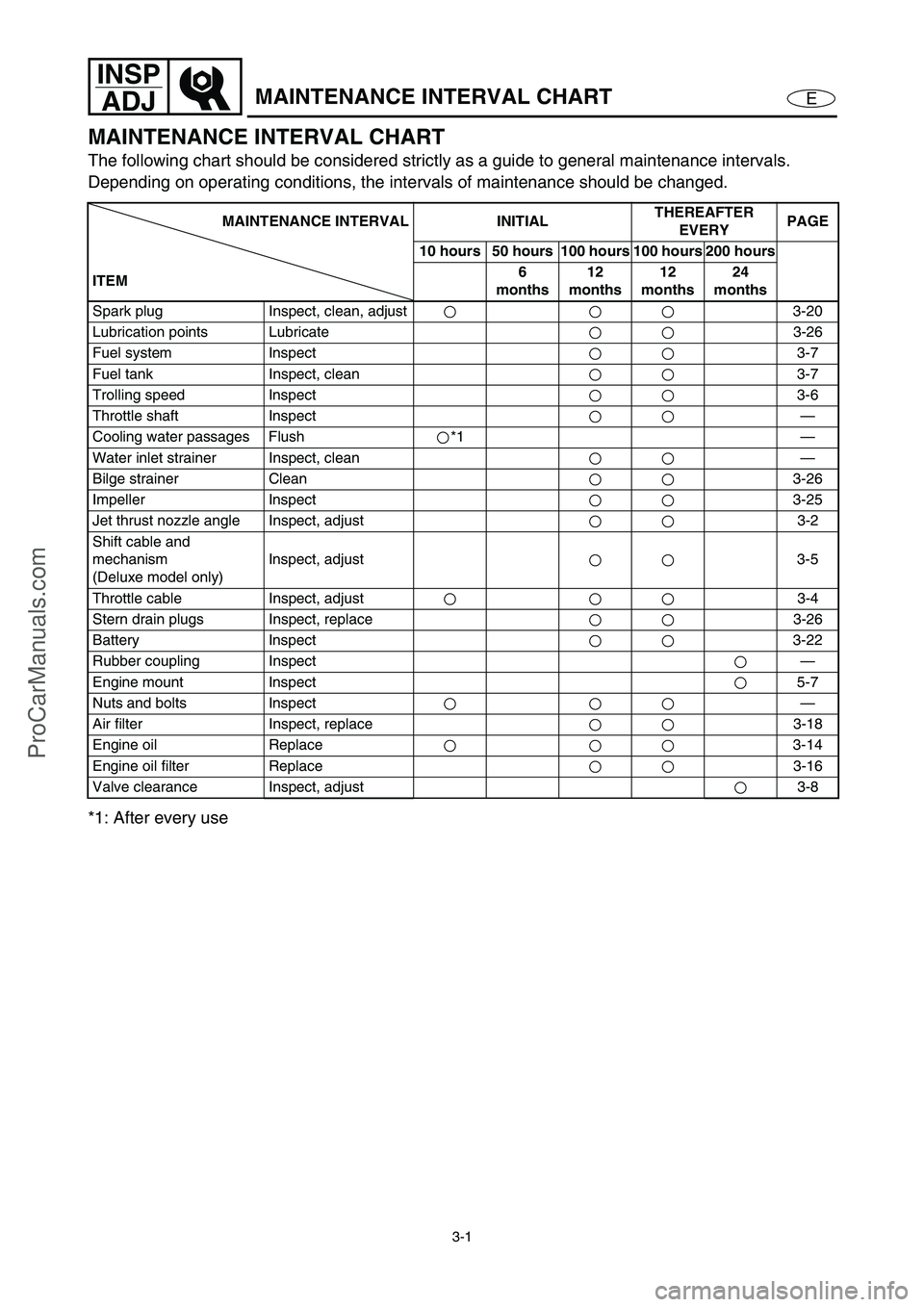
MAINTENANCE INTERVAL CHART
MAINTENANCE INTERVAL CHART
The following chart should be considered strictly as a guide to general maintenance intervals.
Depending on operating conditions, the intervals of maintenance should be changed.
*1: After every use
MAINTENANCE INTERVAL INITIALTHEREAFTER
EVERYPAGE
10 hours 50 hours 100 hours 100 hours 200 hours
ITEM6
months12
months12
months24
months
Spark plug Inspect, clean, adjust 3-20
Lubrication points Lubricate 3-26
Fuel system Inspect3-7
Fuel tank Inspect, clean 3-7
Trolling speed Inspect3-6
Throttle shaft Inspect—
Cooling water passages Flush *1 —
Water inlet strainer Inspect, clean —
Bilge strainer Clean3-26
Impeller Inspect3-25
Jet thrust nozzle angle Inspect, adjust 3-2
Shift cable and
mechanism
(Deluxe model only)Inspect, adjust 3-5
Throttle cable Inspect, adjust 3-4
Stern drain plugs Inspect, replace 3-26
Battery Inspect 3-22
Rubber coupling Inspect—
Engine mount Inspect5-7
Nuts and bolts Inspect—
Air filter Inspect, replace 3-18
Engine oil Replace 3-14
Engine oil filter Replace 3-16
Valve clearance Inspect, adjust 3-8
ProCarManuals.com
Page 57 of 347

3-8
E
INSP
ADJ
FUEL SYSTEM/POWER UNIT
Water separator inspection
1. Inspect:
Water separator 1
Water accumulation →
Drain.
NOTE:
To drain the water, remove the drain plug.
POWER UNIT
Valve clearance adjustment
The following procedure applies to all of the
valves.
NOTE:
Valve clearance adjustment should be made
on a cold engine, at room temperature.
When the valve clearance is to be measured
or adjusted, the piston must be at top dead
center (TDC) of the compression stroke.
1. Remove:
Ignition coils
Spark plugs
Cylinder head cover
Cylinder head cover gasket
Refer to “CAMSHAFTS” in Chapter 5.
2. Install:
Dial gauge needle
Dial gauge stand 1
(into spark plug hole #1)
Dial gauge 2
Dial gauge stand:
90890-06583
Dial gauge needle:
90890-06584
Dial gauge stand set:
YB-06585/90890-06585
Dial indicator gauge:
YU-03097
Dial gauge set:
90890-012522
1
ProCarManuals.com
Page 103 of 347

5-4
EPOWRENGINE UNIT
SERVICE POINTS
Compression pressure measurement
The following procedure applies to all of the
cylinders.
NOTE:
Insufficient compression pressure will result in
a loss of performance.
1. Measure:
Valve clearance
Out of specification →
Adjust.
Refer to “POWER UNIT” in Chapter 3.
2. Warm the engine up, and then put the
watercraft in a horizontal position.
3. Remove:
Ignition coils
Spark plugs
CAUTION:
Before removing the spark plugs, use com-
pressed air to blow away any dirt accumu-
lated in the spark plug wells to prevent it
from falling into the cylinders.
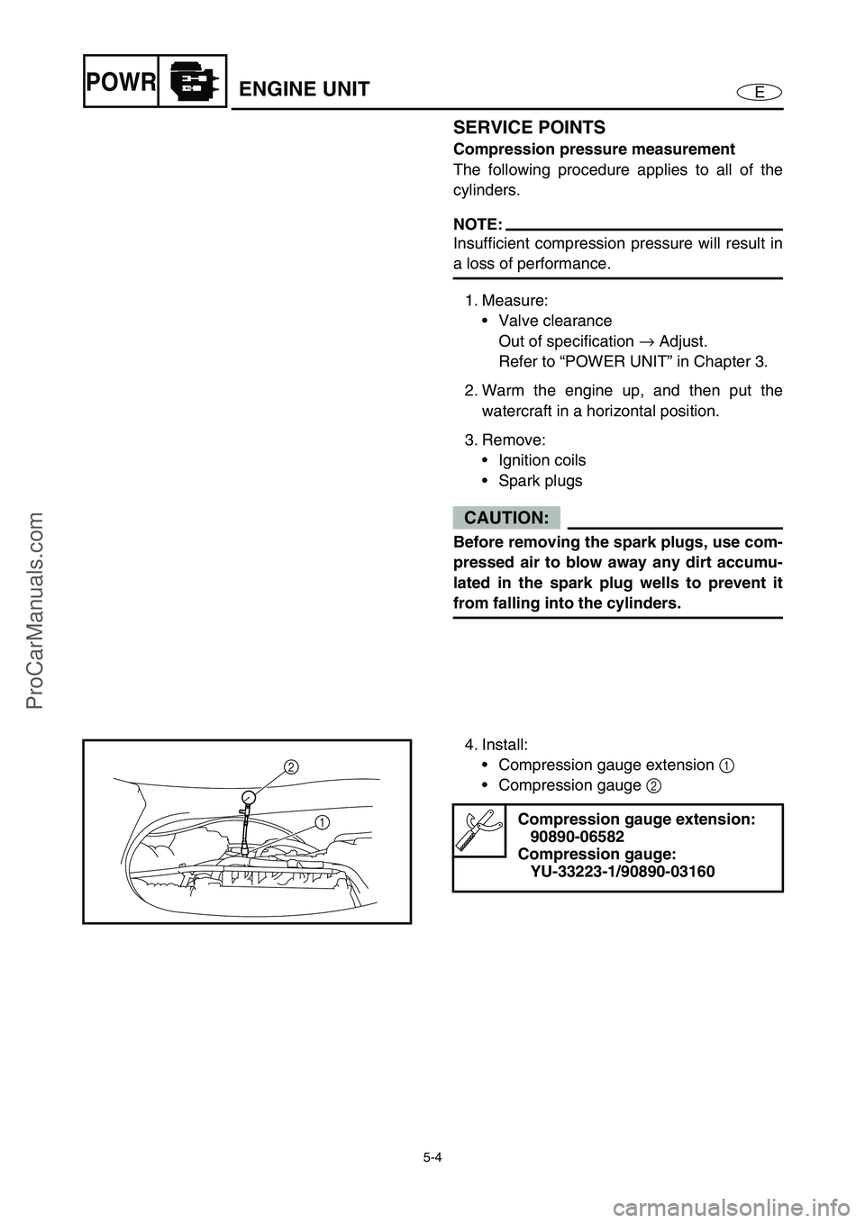
4. Install:
Compression gauge extension 1
Compression gauge 2
Compression gauge extension:
90890-06582
Compression gauge:
YU-33223-1/90890-03160
2
1
ProCarManuals.com
Page 225 of 347

E
–+ELEC
1
2
3
4
5
6
7
8
9
CHAPTER 7
ELECTRICAL SYSTEM
ELECTRICAL COMPONENTS........................................................................ 7-1
FUSE BOX ....................................................................................................... 7-2
EXPLODED DIAGRAM ............................................................................. 7-2
REMOVAL AND INSTALLATION CHART ................................................ 7-2
ECM AND RECTIFIER/REGULATOR............................................................. 7-7
EXPLODED DIAGRAM ............................................................................. 7-7
REMOVAL AND INSTALLATION CHART ................................................ 7-7
ELECTRICAL ANALYSIS ............................................................................... 7-9
INSPECTION............................................................................................. 7-9
Digital tester ........................................................................................ 7-9
Low resistance measurement ........................................................... 7-10
Peak voltage measurement .............................................................. 7-10
Peak voltage adapter ........................................................................ 7-11
Test harness .................................................................................... 7-11
IGNITION SYSTEM ....................................................................................... 7-12
WIRING DIAGRAM ................................................................................. 7-12
IGNITION SPARK ................................................................................... 7-14
IGNITION SYSTEM PEAK VOLTAGE .................................................... 7-15
BATTERY ................................................................................................ 7-17
FUSE ....................................................................................................... 7-17
SPARK PLUGS ....................................................................................... 7-17
IGNITION COIL ....................................................................................... 7-18
ENGINE STOP SWITCH ......................................................................... 7-18
ENGINE TEMPERATURE SENSOR ...................................................... 7-19
SENSOR ASSEMBLY ............................................................................. 7-19
THERMOSWITCH (ENGINE).................................................................. 7-20
THERMOSWITCH (EXHAUST) .............................................................. 7-21
MAIN AND FUEL PUMP RELAY............................................................. 7-22
ELECTRONIC CONTROL THROTTLE VALVE RELAY ......................... 7-23
THROTTLE POSITION SENSOR ........................................................... 7-24
ACCELERATOR POSITION SENSOR ................................................... 7-26
CAM POSITION SENSOR ...................................................................... 7-29
SLANT DETECTION SWITCH ................................................................ 7-30
ProCarManuals.com
Page 228 of 347

7-1
E
–+ELECELECTRICAL COMPONENTS
ELECTRICAL COMPONENTS
O
N
M
L
K
J
I
H
G
F
E
D
C
B
A
0
91
2
3
4
5
6
7
8
1Thermoswitch (engine)
2Fuse box
3Slant detection switch
4Starter motor
5Engine temperature sensor
6Spark plugs and ignition coils
7Cam position sensor
8Battery
9Speed sensor
0Sensor assembly (intake air
pressure and intake air tem-
perature)AOil pressure switch
BFuel injectors
CThermoswitch (exhaust)
DRectifier/regulator
EECM
FThrottle body assembly
GLighting coil and pickup coil
HEngine stop switch, engine
shut-off switch, and start
switch
ISteering sensor
JBuzzerKAccelerator position sensor
LElectric fuel pump
MFuel sender
NMultifunction meter
ORemote control unit (Deluxe
model only)
ProCarManuals.com
Page 237 of 347

7-10
E
–+ELECELECTRICAL ANALYSIS
Low resistance measurement
NOTE:
When measuring a resistance of 10 Ω
or less
using a digital tester, the correct measure-
ment cannot be obtained because of the
tester’s internal resistance.
To obtain the correct value, subtract the
internal resistance from the displayed mea-
surement.
The internal resistance of the tester can be
obtained by connecting both of its terminals.
Correct value =
Displayed measurement –
Internal resistance
Peak voltage measurement
NOTE:
When checking the condition of the ignition
system it is vital to know the peak voltage.
Cranking speed is dependant on many fac-
tors (e.g., fouled or weak spark plugs, a
weak battery). If one of these is defective,
the peak voltage will be lower than specifica-
tion.
If the peak voltage measurement is not
within specification the engine will not oper-
ate properly.
A low peak voltage will also cause compo-
nents to prematurely wear.
ProCarManuals.com
Page 244 of 347

7-17
E
–+ELEC
NOTE:
To crank the engine, connect the engine shut-
off cord (lanyard) to the engine shut-off switch,
and then press the start switch and engine
stop switch simultaneously.
4. Measure:
Rectifier/regulator output voltage
Below specification →
Replace the recti-
fier/regulator.
NOTE:
Do not use the peak voltage adapter to mea-
sure the output voltage.
Disconnect the output lead of the tester har-
ness.
Test harness (6 pins):
YB-06848
Test harness FSW-6A (6 pins):
90890-06848
Rectifier/regulator output
voltage:
Red (R) – Black (B)
r/minUnloaded
3,500
V 13.0
BATTERY
Refer to “ELECTRICAL” in Chapter 3.
FUSE
Refer to “STARTING SYSTEM”.
SPARK PLUGS
Refer to “POWER UNIT” in Chapter 3.
IGNITION SYSTEM
ProCarManuals.com
Page 339 of 347

9-6
E
TRBL
ANLS
TROUBLE ANALYSIS
JET PUMP UNIT
Duct 6
Impeller 6
Intake grate 6
Bearings 6
Water inlet hose 6
Bilge hose 6
Bilge strainer 3
Bilge hose joint 6
ELECTRICAL
Ignition system, fuel control system
Pickup coils 7
ECM 7
Ignition coils 7
Slant detection switch 7
Engine stop switch 7
Engine shut-off switch 7
Spark plugs 3
Main and fuel pump relay 7
Electronic control throttle
valve relay7
Thermoswitch 7
Sensor assembly 7
Engine temperature
sensor7
Throttle body assembly
(throttle position sensor)7
Accelerator position
sensor7
Cam position sensor 7 Trouble mode Check elements
ENGINE WILL NOT START
HARD STARTING
ROUGH IDLING
HIGH IDLING
ENGINE STALLS
POOR ACCELERATION
ENGINE WILL NOT STOP
POOR PERFORMANCE
LIMITED ENGINE SPEED
OVERHEATING
LOW OIL PRESSURE
LOOSE STEERING
BILGE INCREASE
IRREGULAR WARNING INDICATION
POOR BATTERY CHARGING
Relative partReference
chapter
ProCarManuals.com