torque YAMAHA VX110 2005 Service Manual
[x] Cancel search | Manufacturer: YAMAHA, Model Year: 2005, Model line: VX110, Model: YAMAHA VX110 2005Pages: 347, PDF Size: 14.17 MB
Page 5 of 347
E
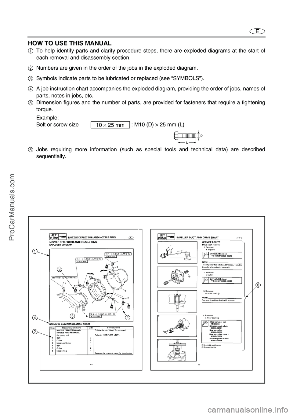
HOW TO USE THIS MANUAL
1To help identify parts and clarify procedure steps, there are exploded diagrams at the start of
each removal and disassembly section.
2Numbers are given in the order of the jobs in the exploded diagram.
3Symbols indicate parts to be lubricated or replaced (see “SYMBOLS”).
4A job instruction chart accompanies the exploded diagram, providing the order of jobs, names of
parts, notes in jobs, etc.
5Dimension figures and the number of parts, are provided for fasteners that require a tightening
torque.
Example:
Bolt or screw size : M10 (D) × 25 mm (L)
6Jobs requiring more information (such as special tools and technical data) are described
sequentially.10 × 25 mm
D
L
ProCarManuals.com
Page 6 of 347
E
A50001-1-4
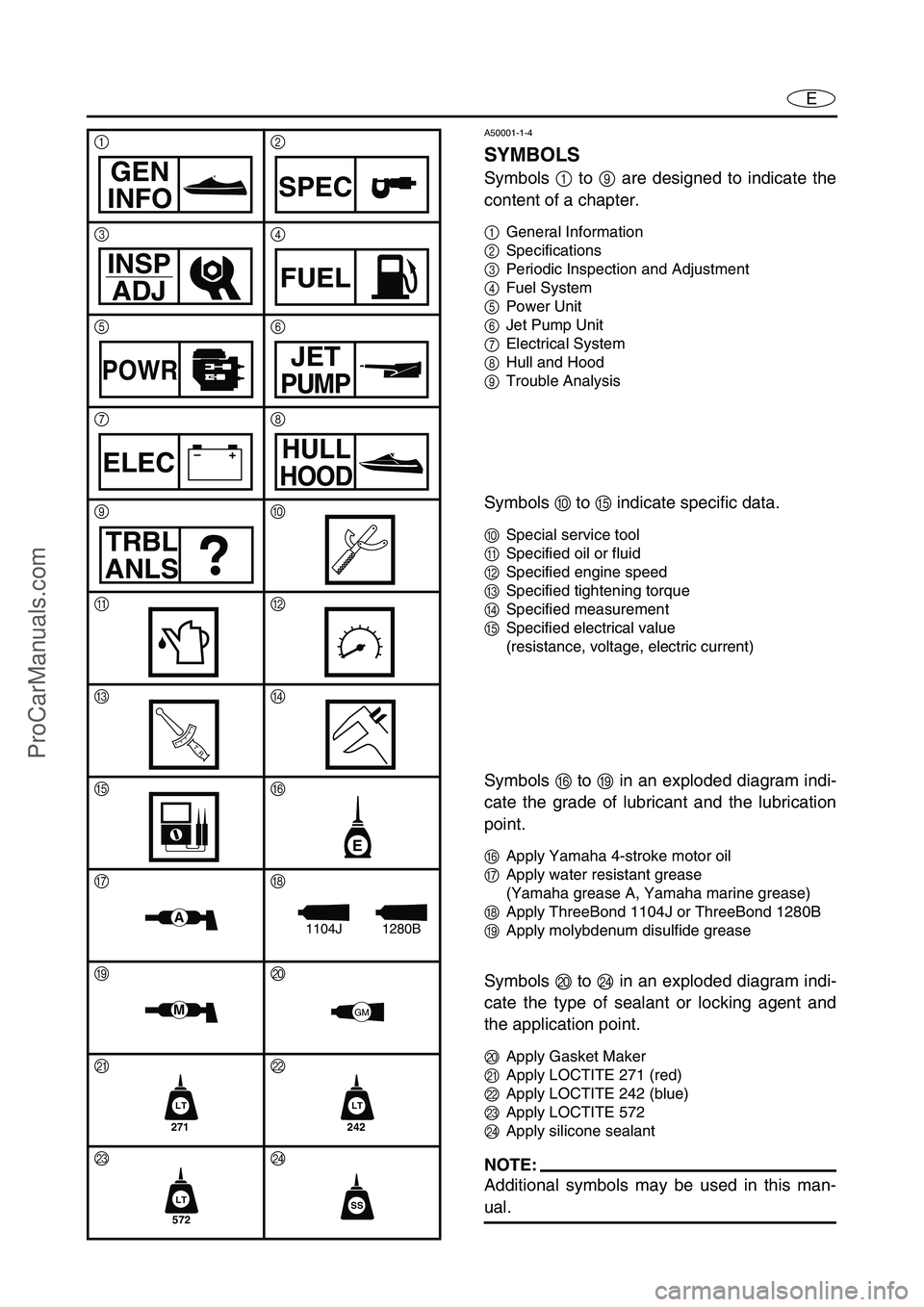
SYMBOLS
Symbols 1 to 9 are designed to indicate the
content of a chapter.
1General Information
2Specifications
3Periodic Inspection and Adjustment
4Fuel System
5Power Unit
6Jet Pump Unit
7Electrical System
8Hull and Hood
9Trouble Analysis
Symbols 0 to E indicate specific data.
0Special service tool
ASpecified oil or fluid
BSpecified engine speed
CSpecified tightening torque
DSpecified measurement
ESpecified electrical value
(resistance, voltage, electric current)
Symbols F to I in an exploded diagram indi-
cate the grade of lubricant and the lubrication
point.
FApply Yamaha 4-stroke motor oil
GApply water resistant grease
(Yamaha grease A, Yamaha marine grease)
HApply ThreeBond 1104J or ThreeBond 1280B
IApply molybdenum disulfide grease
Symbols J to N in an exploded diagram indi-
cate the type of sealant or locking agent and
the application point.
JApply Gasket Maker
KApply LOCTITE 271 (red)
LApply LOCTITE 242 (blue)
MApply LOCTITE 572
NApply silicone sealant
NOTE:
Additional symbols may be used in this man-
ual.
12
34
56
78
90
AB
CD
EF
GH
IJ
KL
MN
GEN
INFOSPEC
INSP
ADJFUEL
POWRJET
PUMP
–+ELECHULL
HOOD
TRBL
ANLS
T R..
E
A1280B1104J
MGM
271
LT
242
LT
572
LTSS
ProCarManuals.com
Page 12 of 347

1-3
E
GEN
INFO
SAFETY WHILE WORKING
Under normal conditions, the lubricants men-
tioned in this manual should not harm or be
hazardous to your skin. However, you should
follow these precautions to minimize any risk
when working with lubricants.
1. Maintain good standards of personal and
industrial hygiene.
2. Change and wash clothing as soon as
possible if soiled with lubricants.
3. Avoid contact with skin. Do not, for exam-
ple, place a soiled rag in your pocket.
4. Wash hands and any other part of the
body thoroughly with soap and hot water
after contact with a lubricant or lubricant
soiled clothing has been made.
5. To protect your skin, apply a protective
cream to your hands before working on the
watercraft.
6. Keep a supply of clean, lint-free cloths for
wiping up spills, etc.
GOOD WORKING PRACTICES
1.The right tools
Use the recommended special service
tools to protect parts from damage. Use
the right tool in the right manner—do not
improvise.
2.Tightening torques
Follow the tightening torque specifications
provided throughout the manual. When
tightening nuts, bolts, and screws, tighten
the large sizes first, and tighten fasteners
starting in the center and moving outward.
ProCarManuals.com
Page 21 of 347

ESPEC
1
2
3
4
5
6
7
8
9
CHAPTER 2
SPECIFICATIONS
GENERAL SPECIFICATIONS ....................................................................... 2-1
MAINTENANCE SPECIFICATIONS ............................................................... 2-3
ENGINE .................................................................................................... 2-3
JET PUMP UNIT ...................................................................................... 2-6
HULL AND HOOD .................................................................................... 2-6
ELECTRICAL ............................................................................................ 2-7
TIGHTENING TORQUES .............................................................................. 2-10
SPECIFIED TORQUES ........................................................................... 2-10
GENERAL TORQUE ............................................................................... 2-15
CABLE AND HOSE ROUTING ..................................................................... 2-16
ProCarManuals.com
Page 31 of 347
2-10
ESPECTIGHTENING TORQUES
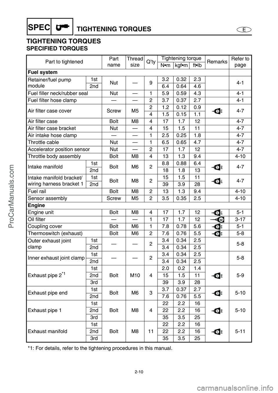
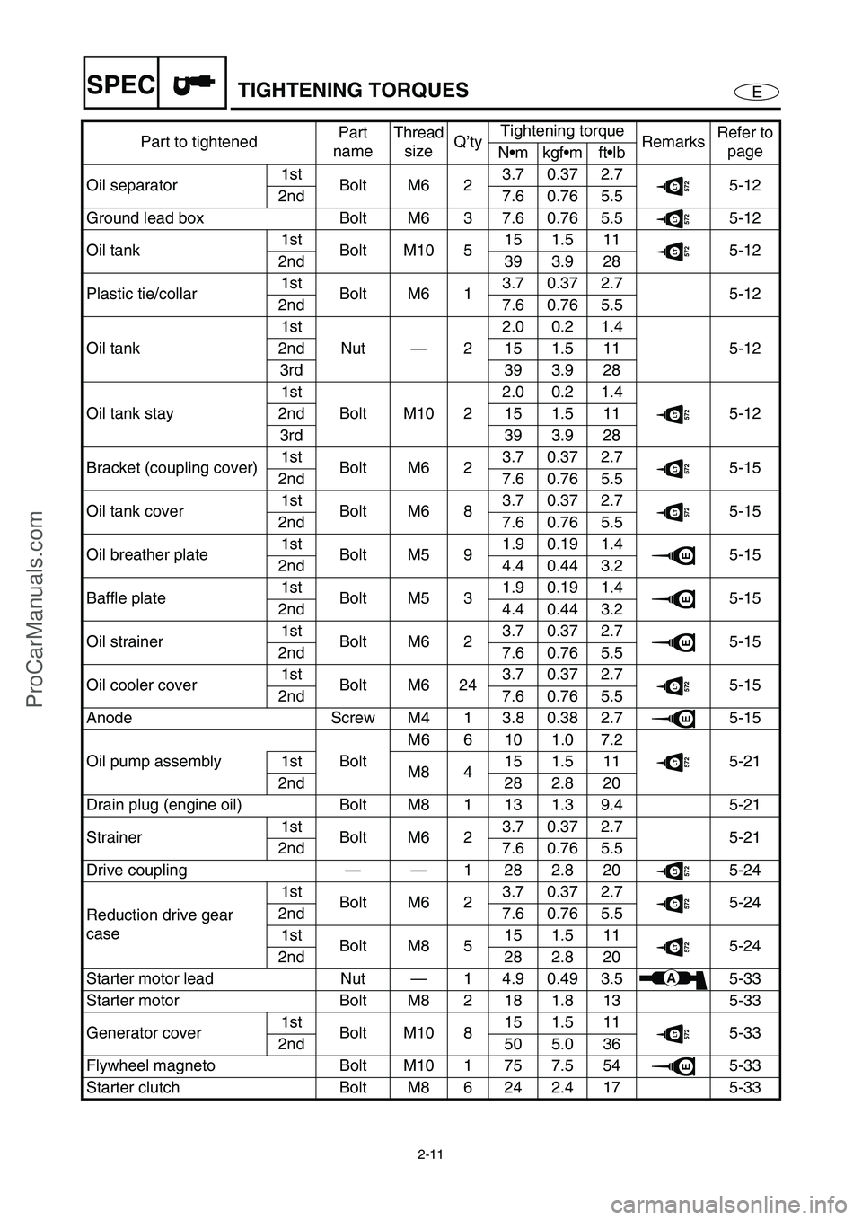
TIGHTENING TORQUES
SPECIFIED TORQUES
Part to tightenedPart
nameThread
sizeQ’tyTightening torque
RemarksRefer to
page
Nmkgfmftlb
Fuel system
Retainer/fuel pump
module1st
Nut—93.20.322.3
4-1
2nd 6.4 0.64 4.6
Fuel filler neck/rubber seal Nut—1 5.9 0.59 4.3 4-1
Fuel filter hose clamp——2 3.7 0.37 2.7 4-1
Air filter case cover Screw M52 1.2 0.12 0.9
572LT4-7
4 1.5 0.15 1.1
Air filter case Bolt M8 4 17 1.7 12 4-7
Air filter case bracket Nut—4 15 1.5 11 4-7
Air intake hose clamp——1 2.5 0.25 1.8 4-7
Throttle cable Nut—1 6.5 0.65 4.7 4-7
Accelerator position sensor Nut—2 17 1.7 12 4-7
Throttle body assembly Bolt M8 4 13 1.3 9.4 4-10
Intake manifold1st
Bolt M6 28.80.886.4
242LT4-7
2nd 18 1.8 13
Intake manifold bracket/
wiring harness bracket 11st
Bolt M8 215 1.5 11
271LT4-7
2nd 39 3.9 28
Fuel rail Bolt M8 2 13 1.3 9.4 4-10
Sensor assembly Screw M5 2 3.5 0.35 2.5 4-10
Engine
Engine unit Bolt M8 4 17 1.7 12
271LT5-1
Oil filter——1171.712
E3-17
Coupling cover Bolt M6 1 7.8 0.78 5.6
572LT5-1
Thermoswitch (exhaust) Bolt M6 2 7.6 0.76 5.5
572LT5-8
Outer exhaust joint
clamp1st
——23.40.342.5
5-8
2nd 3.4 0.34 2.5
Inner exhaust joint clamp1st
——23.40.342.5
5-8
2nd 3.4 0.34 2.5
Exhaust pipe 2
*1 1st
Bolt M10 42.0 0.2 1.4242LT5-9 2nd 15 1.5 11
3rd 39 3.9 28
Exhaust pipe end1st
Bolt M6 33.70.372.7
572LT5-10
2nd 7.6 0.76 5.5
Exhaust pipe 11st
Bolt M8 422 2.2 16
242LT5-10 2nd 22 2.2 16
3rd 35 3.5 25
Exhaust manifold1st
Bolt M8 1122 2.2 16
242LT5-11 2nd 22 2.2 16
3rd 35 3.5 25
*1: For details, refer to the tightening procedures in this manual.
ProCarManuals.com
Page 32 of 347
2-11
ESPECTIGHTENING TORQUES
Oil separator1st
Bolt M6 23.70.372.7572LT5-12
2nd 7.6 0.76 5.5
Ground lead box Bolt M6 3 7.6 0.76 5.5
572LT5-12
Oil tank1st
Bolt M10 515 1.5 11
572LT5-12
2nd 39 3.9 28
Plastic tie/collar1st
Bolt M6 13.70.372.7
5-12
2nd 7.6 0.76 5.5
Oil tank1st
Nut—22.0 0.2 1.4
5-12 2nd 15 1.5 11
3rd 39 3.9 28
Oil tank stay1st
Bolt M10 22.0 0.2 1.4
572LT5-12 2nd 15 1.5 11
3rd 39 3.9 28
Bracket (coupling cover)1st
Bolt M6 23.70.372.7
572LT5-15
2nd 7.6 0.76 5.5
Oil tank cover1st
Bolt M6 83.70.372.7
572LT5-15
2nd 7.6 0.76 5.5
Oil breather plate1st
Bolt M5 91.90.191.4
E5-15
2nd 4.4 0.44 3.2
Baffle plate1st
Bolt M5 31.90.191.4
E5-15
2nd 4.4 0.44 3.2
Oil strainer1st
Bolt M6 23.70.372.7
E5-15
2nd 7.6 0.76 5.5
Oil cooler cover1st
Bolt M6 243.70.372.7
572LT5-15
2nd 7.6 0.76 5.5
Anode Screw M4 1 3.8 0.38 2.7
E5-15
Oil pump assembly BoltM6 6 10 1.0 7.2
572LT5-21 1st
M8 415 1.5 11
2nd 28 2.8 20
Drain plug (engine oil) Bolt M8 1 13 1.3 9.4 5-21
Strainer1st
Bolt M6 23.70.372.7
5-21
2nd 7.6 0.76 5.5
Drive coupling——1282.820
572LT5-24
Reduction drive gear
case1st
Bolt M6 23.70.372.7
572LT5-24
2nd 7.6 0.76 5.5
1st
Bolt M8 515 1.5 11
572LT5-24
2nd 28 2.8 20
Starter motor lead Nut—1 4.9 0.49 3.5
A5-33
Starter motor Bolt M8 2 18 1.8 13 5-33
Generator cover1st
Bolt M10 815 1.5 11
572LT5-33
2nd 50 5.0 36
Flywheel magneto Bolt M10 1 75 7.5 54
E5-33
Starter clutch Bolt M8 6 24 2.4 17 5-33Part to tightenedPart
nameThread
sizeQ’tyTightening torque
RemarksRefer to
page
Nmkgfmftlb
ProCarManuals.com
Page 33 of 347
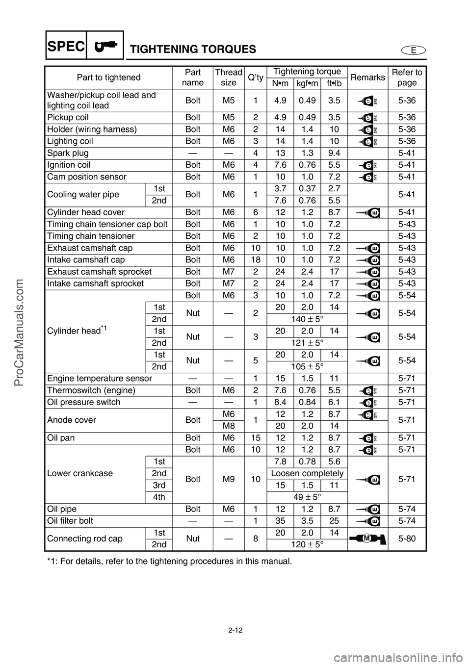
2-12
ESPECTIGHTENING TORQUES
Washer/pickup coil lead and
lighting coil leadBolt M5 1 4.9 0.49 3.5242LT5-36
Pickup coil Bolt M5 2 4.9 0.49 3.5
242LT5-36
Holder (wiring harness) Bolt M6 2 14 1.4 10
242LT5-36
Lighting coil Bolt M6 3 14 1.4 10
242LT5-36
Spark plug——4131.39.4 5-41
Ignition coil Bolt M6 4 7.6 0.76 5.5
572LT5-41
Cam position sensor Bolt M6 1 10 1.0 7.2
572LT5-41
Cooling water pipe1st
Bolt M6 13.70.372.7
5-41
2nd 7.6 0.76 5.5
Cylinder head cover Bolt M6 6 12 1.2 8.7
E5-41
Timing chain tensioner cap bolt Bolt M6 1 10 1.0 7.2 5-43
Timing chain tensioner Bolt M6 2 10 1.0 7.2 5-43
Exhaust camshaft cap Bolt M6 10 10 1.0 7.2
E5-43
Intake camshaft cap Bolt M6 18 10 1.0 7.2
E5-43
Exhaust camshaft sprocket Bolt M7 2 24 2.4 17
E5-43
Intake camshaft sprocket Bolt M7 2 24 2.4 17
E5-43
Cylinder head
*1 Bolt M6 3 10 1.0 7.2
E5-54
1st
Nut—220 2.0 14
E5-54
2nd 140 ±
5°
1st
Nut—320 2.0 14
E5-54
2nd 121 ±
5°
1st
Nut—520 2.0 14
E5-54
2nd 105 ±
5°
Engine temperature sensor——1 15 1.5 11 5-71
Thermoswitch (engine) Bolt M6 2 7.6 0.76 5.5
572LT5-71
Oil pressure switch——1 8.4 0.84 6.1
572LT5-71
Anode cover BoltM6
112 1.2 8.7
271LT5-71
M8 20 2.0 14
Oil pan Bolt M6 15 12 1.2 8.7
572LT5-71
Lower crankcaseBolt M6 10 12 1.2 8.7
572LT5-71
1st
Bolt M9 107.80.785.6
E5-71 2nd Loosen completely
3rd 15 1.5 11
4th 49 ±
5°
Oil pipe Bolt M6 1 12 1.2 8.7
E5-74
Oil filter bolt——1353.525
E5-74
Connecting rod cap1st
Nut—820 2.0 14
M5-80
2nd 120 ±
5°
*1: For details, refer to the tightening procedures in this manual.Part to tightenedPart
nameThread
sizeQ’tyTightening torque
RemarksRefer to
page
Nmkgfmftlb
ProCarManuals.com
Page 34 of 347

2-13
ESPECTIGHTENING TORQUES
Jet pump unit
Steering cable joint Nut — 1 6.8 0.68 4.9
242LT6-3
Ride plate Bolt M8 4 17 1.7 12
572LT6-1
Intake grate BoltM6
27.60.765.5
242LT6-1
M10 40 4.0 29
Speed sensor Screw M5 4 3.7 0.37 2.7
242LT6-1
Jet pump unit assembly BoltM6 1 7.8 0.78 5.6
572LT6-3
M10 4 40 4.0 29
Rubber plateBolt M6 4
6.80.684.9 6-3
Nut — 2
Bracket Bolt M8 217 1.7 12
6-3
14 1.4 10
271LT
Reverse gate Bolt M8 2 15 1.5 11271LT6-5
Reverse gate ball joint Nut — 1 7.8 0.78 5.6
242LT6-5
Reverse gate spring Nut — 1 7.8 0.78 5.6
242LT6-5
Spout hose clamp — —1 1.2 0.12 0.9 6-5
1 2.2 0.22 1.6 6-3
Jet thrust nozzle Bolt M8 2 15 1.5 11
271LT6-6
Nozzle/bracket Bolt M10 4 40 4.0 29
572LT6-6
Water inlet cover/water inlet
strainerBolt M6 4 6.6 0.66 4.8
572LT6-6
Cap Bolt M6 3 7.8 0.78 5.6
572LT6-8
Impeller Impeller M22 1 75 7.5 54
572LT6-8
Transom plate Nut — 4 26 2.6 19 6-15
Intermediate housing cover Bolt M8 4 17 1.7 12
271LT6-18
Driven couplingDriven
couplingM24 1 36 3.6 26
572LT6-19
Clamp — — 2 4.2 0.42 3.0 6-18
Hull and hood
Handlebar holder Bolt M8 4 20 2.0 14
572LT8-1
Upper handlebar cover ScrewM4 2 1.1 0.11 0.8
8-1
M5 4 1.1 0.11 0.8
Lower handlebar cover Screw M6 4 3.7 0.37 2.7
271LT8-1
Throttle lever assembly Screw M5 2 3.4 0.34 2.5 8-4
Handlebar switch assembly Screw M5 2 3.4 0.34 2.5 8-4
Grip end Bolt M5 2 1.2 0.12 0.9
242LT8-4
Steering column Bolt M8 4 17 1.7 12
572LT8-20
Steering cable ball joint Ball joint — 1 6.9 0.69 5.0 8-20
Steering arm Bolt M8 1 20 2.0 14
242LT8-20
Steering sensor Bolt M8 4 16 1.6 12
572LT8-21
Spacer Bolt M8 3 16 1.6 12
572LT8-21
Shift cable holder
(Deluxe model only)Bolt M6 2 6.9 0.69 5.0
242LT8-23
Shift cable seal
(Deluxe model only)Nut — 1 5.9 0.59 4.3 8-23 Part to tightenedPart
nameThread
sizeQ’tyTightening torque
RemarksRefer to
page
Nm kgfm ftlb
ProCarManuals.com
Page 35 of 347

2-14
ESPECTIGHTENING TORQUES
Shift cable locknut
(Deluxe model only)Nut—1 3.8 0.38 2.7572LT8-23
Steering cable locknut
(steering column side)Nut—1 6.5 0.65 4.7 8-23
Steering cable locknut
(jet pump side)Nut—1 6.8 0.68 4.9
572LT8-23
Steering cable seal Nut—1 5.9 0.59 4.3 8-23
Steering cable bracket Bolt M6 1 6.9 0.69 5.0
572LT8-23
Speed sensor lead grommet Nut—1 5.9 0.59 4.3 8-23
Hinge assembly Bolt M6 2 6.9 0.69 5.0 8-8
Hood lock assembly Bolt M5 2 1.9 0.19 1.4
572LT8-8
Hinge assembly Bolt M6 4 6.9 0.69 5.0
242LT8-8
Lid lock hook Bolt M6 2 6.9 0.69 5.0
242LT8-8
Mirror (Deluxe model only) Nut—4 15 1.5 11 8-8
Shift handle lever
(Deluxe model only)Screw M5 2 3.70.372.7
572LT8-11
Multifunction meter Bolt M5 4 3.9 0.39 2.8
572LT8-11
Engine hatch cover
(Deluxe model only)Bolt M6 1 6.9 0.69 5.0
572LT8-11
Engine hatch cover Bolt M6 8 6.9 0.69 5.0
572LT8-11
Detent plate Bolt M6 2 8.0 0.8 5.8
572LT8-16
Shift lever bracket
(Deluxe model only)Nut—2 15 1.5 11 8-16
Pilot water outlet Nut—1 4.2 0.42 3.0 8-17
Hand grip Nut—4 6.9 0.69 5.0 8-28
Seat bracket Nut—2 15 1.5 11 8-28
Seat lock projection Bolt—1 26 2.6 19 8-28
Seat lock assembly Bolt M6 2 6.4 0.64 4.6
271LT8-28
Plate/rubber hose/exhaust
valveNut—6 5.4 0.54 3.9 8-31
Hose clamp 1——2 3.7 0.37 2.7 8-31
Hose clamp 2——1 3.7 0.37 2.7 8-31
Joint clamp 1 and 4——2 3.7 0.37 2.7 8-31
Joint clamp 2 and 31st
——22.40.241.7
8-31
2nd 2.4 0.24 1.7
Sponson Bolt M810161.612
572LT8-36
Cleat Nut—2
15 1.5 11 8-36
4
Spout Nut—1 5.4 0.54 3.9 8-36
Protector (bow) Nut—5 6.9 0.69 5.0 8-36
Bow eye Bolt M6 2 13 1.3 9.4 8-36
Drain plug/packing Screw M5 4 2.0 0.2 1.4 8-36
Engine mount Bolt M8 8 17 1.7 12
572LT8-38
Engine damper Bolt M6 2 6.6 0.66 4.8
271LT8-38 Part to tightenedPart
nameThread
sizeQ’tyTightening torque
RemarksRefer to
page
Nmkgfmftlb
ProCarManuals.com
Page 36 of 347

2-15
ESPECTIGHTENING TORQUES
Electrical
Fuse box Nut—2 17 1.7 12 7-2
Fuse box bracket Nut—4 15 1.5 11 7-2
ECM Bolt M6 4 4.0 0.4 2.9
572LT7-7
Bracket1st
Bolt M8 28.80.886.4
572LT7-7
2nd 18 1.8 13
Slant detection switchTapping
screwø6 2 3.90.392.8 7-2
Rectifier/regulator Bolt M8 2 4.0 0.4 2.9
572LT7-7
Brush assembly/spacer Nut—1 8.8 0.88 6.4 7-39
Starter motor rear cover Bolt M5 2 6.4 0.64 4.6 7-39
Remote control transmitter
coverTapping
screwø2 6 0.1 0.01 0.1 7-64 Part to tightenedPart
nameThread
sizeQ’tyTightening torque
RemarksRefer to
page
Nmkgfmftlb
GENERAL TORQUE
This chart specifies tightening torques for stan-
dard fasteners with a standard ISO thread
pitch. Tightening torque specifications for spe-
cial components or assemblies are provided in
applicable sections of this manual. To avoid
warpage, tighten multi-fastener assemblies in
a crisscross fashion and progressive stages
until the specified tightening torque is reached.
Unless otherwise specified, tightening torque
specifications require clean, dry threads.
Components should be at room temperature.Nut A
Bolt B
General torque
specifications
Nmkgfmftlb
8 mm M5 5.0 0.5 3.6
10 mm M6 8.0 0.8 5.8
12 mm M8 18 1.8 13
14 mm M10 36 3.6 26
17 mm M12 43 4.3 31
ProCarManuals.com