engine YAMAHA VXR 2014 User Guide
[x] Cancel search | Manufacturer: YAMAHA, Model Year: 2014, Model line: VXR, Model: YAMAHA VXR 2014Pages: 98, PDF Size: 3.98 MB
Page 30 of 98

Description
24
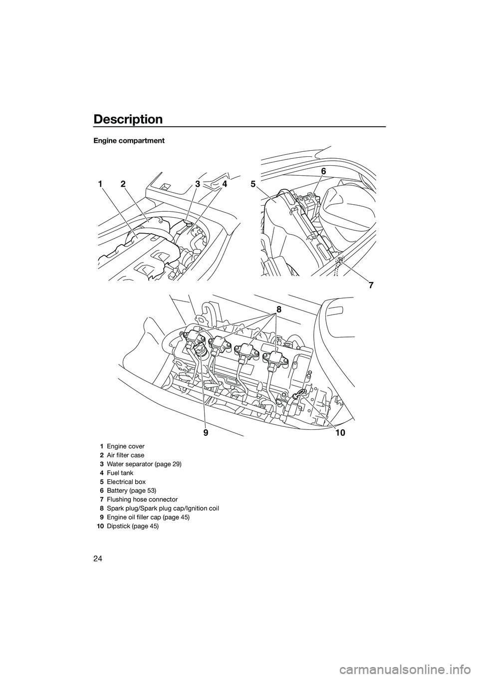
Engine compartment
7
5
6
8
10
9
2143
1 Engine cover
2 Air filter case
3 Water separator (page 29)
4 Fuel tank
5 Electrical box
6 Battery (page 53)
7 Flushing hose connector
8 Spark plug/Spark plug cap/Ignition coil
9 Engine oil filler cap (page 45)
10 Dipstick (page 45)
UF2M73E0.book Page 24 Friday, August 2, 2013 11:28 AM
Page 32 of 98

Control function operation
26
EJU31385Yamaha Security System
The Yamaha Security System functions to
help prevent unauthorized use or theft of the
watercraft. The lock and unlock modes of the
security system can be selected by operating
the remote control transmitter that is included
with this watercraft. The engine cannot be
started if the lock mode of the security sys-
tem is selected. The engine can only be start-
ed if the unlock mode is selected. (See page
25 for information on the remote control
transmitter.)
TIP:
The Yamaha Security System settings can
only be selected while the engine is stopped.
EJU36107Yamaha Security System settingsThe Yamaha Security System settings will be
confirmed by the number of beeps when the
remote control transmitter is operated, and
by the “SECURITY” indicator light of the mul-
tifunction information center. (See page 33
for information on the multifunction informa-
tion center.)
TIP:
The beeper sounds two times for the nor-
mal operation mode or three times for the
Low RPM Mode. (See page 31 for Low
RPM Mode activation procedures.)
If the remote control transmitter is operated
while the multifunction information center is in the standby state, the center will per-
form the initial operation, and then the set-
ting is selected.
To select the lock mode:
Push the lock button on the remote control
transmitter briefly. The beeper sounds once
and the “SECURITY” indicator light blinks
once, then goes off. This indicates the lock
mode is selected.
To select the unlock mode:
Push the “L-Mode” (unlock) button on the re-
mote control transmitter briefly. The beeper
sounds two or three times and the “SECURI-
TY” indicator light blinks two or three times,
then comes on. This indicates the unlock
mode is selected.
Number of beeps Yamaha Security
System mode “SECURI-
TY” indi- cator light
Lock Goes off
Unlock
(normal operation mode) Comes
on
Unlock
(Low RPM Mode) Comes
on
1 Lock button
2 “SECURITY” indicator light
1 “L-Mode” (unlock) button
2 “SECURITY” indicator light
21
2L-Mode1
UF2M73E0.book Page 26 Friday, August 2, 2013 11:28 AM
Page 33 of 98

Control function operation
27
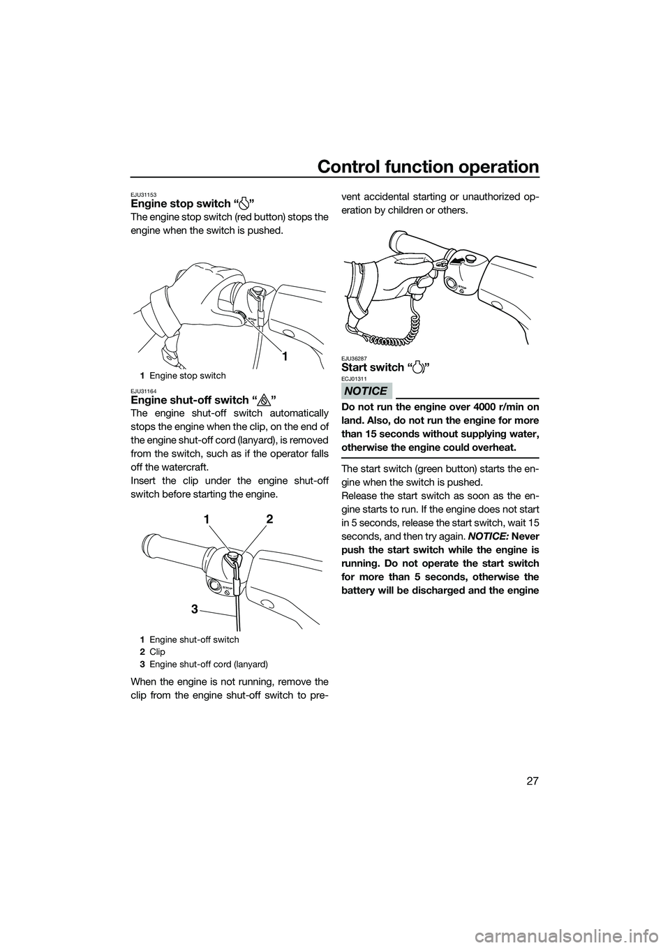
EJU31153Engine stop switch “ ”
The engine stop switch (red button) stops the
engine when the switch is pushed.
EJU31164Engine shut-off switch “ ”
The engine shut-off switch automatically
stops the engine when the clip, on the end of
the engine shut-off cord (lanyard), is removed
from the switch, such as if the operator falls
off the watercraft.
Insert the clip under the engine shut-off
switch before starting the engine.
When the engine is not running, remove the
clip from the engine shut-off switch to pre-vent accidental starting or unauthorized op-
eration by children or others.
EJU36287Start switch “ ”
NOTICE
ECJ01311
Do not run the engine over 4000 r/min on
land. Also, do not run the engine for more
than 15 seconds without supplying water,
otherwise the engine could overheat.
The start switch (green button) starts the en-
gine when the switch is pushed.
Release the start switch as soon as the en-
gine starts to run. If the engine does not start
in 5 seconds, release the start switch, wait 15
seconds, and then try again.
NOTICE: Never
push the start switch while the engine is
running. Do not operate the start switch
for more than 5 seconds, otherwise the
battery will be discharged and the engine
1 Engine stop switch
1 Engine shut-off switch
2 Clip
3 Engine shut-off cord (lanyard)
1
STOP
31
2
UF2M73E0.book Page 27 Friday, August 2, 2013 11:28 AM
Page 34 of 98
![YAMAHA VXR 2014 User Guide Control function operation
28
will not start. Also, the starter motor could
be damaged.
[ECJ01041]
The engine will not start under any of the fol-
lowing conditions:
Lock mode of the Yamaha Securi YAMAHA VXR 2014 User Guide Control function operation
28
will not start. Also, the starter motor could
be damaged.
[ECJ01041]
The engine will not start under any of the fol-
lowing conditions:
Lock mode of the Yamaha Securi](/img/51/52205/w960_52205-33.png)
Control function operation
28
will not start. Also, the starter motor could
be damaged.
[ECJ01041]
The engine will not start under any of the fol-
lowing conditions:
Lock mode of the Yamaha Security System
has been selected. (See page 26 for
Yamaha Security System setting proce- dures.)
Clip is removed from the engine shut-off
switch.
Throttle lever is squeezed.EJU31212Throttle lever
The throttle lever increases the engine speed
when the lever is squeezed.
The throttle lever returns automatically to its
fully closed (idle) position when released.
EJU31262Steering system
By turning the handlebars in the direction you
wish to travel, the angle of the jet thrust noz-
zle is changed, and the direction of the water-
craft is changed accordingly.
Since the strength of the jet thrust determines
the speed and degree of a turn, throttle must
always be applied when attempting a turn,
except at trolling speed.
This model is equipped with the Yamaha En-
gine Management System (YEMS) that in-
cludes an off-throttle steering (OTS) system.
It will activate at planing speeds should you
attempt to steer the watercraft after releasing
the throttle lever. The OTS system assists in
turning by continuing to supply some thrust
while the watercraft is decelerating, but you
can turn more sharply if you apply throttle
while turning the handlebars. The OTS sys-
tem does not function below planing speeds
or when the engine is off. Once the engine
slows down, the watercraft will no longer turn
1 Start switch
1 Throttle lever
START
1
1
1Handlebar
2 Jet thrust nozzle
2
1
UF2M73E0.book Page 28 Friday, August 2, 2013 11:28 AM
Page 35 of 98

Control function operation
29
in response to handlebar input until you apply
throttle again or you reach trolling speed.
EJU35975Cooling water pilot outlet
When the engine is running, some of the
cooling water that is circulated in the engine
is discharged from the cooling water pilot
outlet.
There is a cooling water pilot outlet on the
port (left) side of the watercraft. To check for
proper operation of the cooling system, make
sure that water is being discharged from the
cooling water pilot outlet. If water is not being
discharged from the outlet, stop the engine
and check the jet intake for clogging. (See
page 85 for information on the jet intake.)
TIP:
It will take about 60 seconds for the water
to reach the outlet after the engine is start-
ed.
Water discharge may not be constant
when the engine is running at idling speed.
If this occurs, apply a little throttle to make
sure that water discharges properly.
EJU40323Water separator
The water separator prevents water from en-
tering the fuel tank by collecting any water
that has entered the fuel tank breather hose if
the watercraft was capsized.If water has collected in the water separator,
drain it by loosening the drain screw.
To drain water from the water separator:
(1) Place a drain pan or dry cloth under the
water separator.
(2) Gradually loosen the drain screw to drain the water. Catch the draining water in the
drain pan or soak it up with the dry cloth
so that it does not spill into the engine
compartment. If any water spills into the
watercraft, be sure to wipe it up with a
dry cloth.
(3) Securely tighten the drain screw until it stops.
1Cooling water pilot outlet
1
1Water separator
1 Drain screw
1
1
UF2M73E0.book Page 29 Friday, August 2, 2013 11:28 AM
Page 37 of 98

Watercraft operation
31
EJU40001
Watercraft operation modes
EJU41961Low RPM Mode
The Low RPM Mode is a function that limits
the maximum engine speed to approximately
70% of the maximum engine speed in the
normal mode.
The Low RPM Mode can only be activated
and deactivated by operating the remote
control transmitter that is included with this
watercraft. (See page 25 for information on
the remote control transmitter.)
TIP:
The Low RPM Mode can only be activated
when the engine is stopped in the unlock
mode of the Yamaha Security System.
Activating and deactivating the Low RPM
Mode
Activation of the Low RPM Mode will be con-
firmed by the number of beeps when the re-
mote control transmitter is operated, and by
the “L-MODE” indicator light of the multifunc-
tion information center. (See page 33 for in-
formation on the mult ifunction information
center.)
TIP:
If the remote control transmitter is operated
while the multifunction information center is
in the standby state, the center performs the
initial operation, and then the setting is se-
lected.
To activate the Low RPM Mode:
Push the “L-Mode” (unlock) button on the re-
mote control transmitter for more than 4 sec-
onds. Once the beeper sounds three times
and the “SECURITY” indicator light blinks
three times, then comes on, the “L-MODE”
indicator light comes on and the Low RPM
Mode is activated.
TIP:
If the Low RPM Mode is activated immediate-
ly after the information display turns off, the
“L-MODE” indicator light will not come on.1 Remote control transmitter
Number of
beeps Low RPM Mode
operation “L-MO-
DE” indi- cator light
Activated Comes
on
Deactivated Goes off
UF2M73E0.book Page 31 Friday, August 2, 2013 11:28 AM
Page 38 of 98

Watercraft operation
32
The “L-MODE” indicator light will come on
when the engine is started.
To deactivate the Low RPM Mode:
Push the “L-Mode” (unlock) button on the re-
mote control transmitter for more than 4 sec-
onds. Once the beeper sounds two times and
the “SECURITY” indicator light blinks two
times, then comes on, the “L-MODE” indica-
tor light goes off and the Low RPM Mode is
deactivated. When the Low RPM Mode is de-
activated, the watercraft returns to the nor-
mal operation mode.
1“L-Mode” (unlock) button
1 “SECURITY” indicator light
2 “L-MODE” indicator light
L-Mode1
12
UF2M73E0.book Page 32 Friday, August 2, 2013 11:28 AM
Page 39 of 98

Instrument operation
33
EJU41851
Multifunction information center
The multifunction information center displays
various watercraft information.
Multifunction information center initial op-
eration
When the multifunction information center is
activated, all of the display segments and the
“SECURITY” indicator light come on. After 2
seconds, the warning indicators in the infor-
mation display go off, and then the center
starts to operate normally.
TIP:
The “SECURITY” indicator light will go off
when the engine is started.
Multifunction information center standby
state
If the multifunction information center does
not receive any operation input within 25 sec-
onds after the engine stops, the center will
turn off and enter a standby state. When the
engine is started again, the displays return to
their state before the center turned off, and
then the center starts to operate normally.
EJU35025Information display
The information display shows watercraft op-
erating conditions.
EJU31504Speedometer
The speedometer shows the watercraft
speed against water.
By switching the display units, the speed can
be shown in kilometers per hour “km/h” or
miles per hour “mph”.
TIP:
“mph” is selected as the display unit at the
Yamaha factory.
1 “SECURITY” indicator light
2 Select button
3 Information display
4 “L-MODE” indicator light
5 “WARNING” indicator light
21345
1Tachometer
2 Speedometer
3 Hour meter/voltmeter
4 Fuel level meter
5 Check engine warning indicator
6 Engine overheat warning indicator
7 Oil pressure warning indicator
8 Fuel level warning indicator
1 Speedometer
1234
8765
1
UF2M73E0.book Page 33 Friday, August 2, 2013 11:28 AM
Page 40 of 98

Instrument operation
34
To switch the speedometer display units:
Push the select button for at least 1 second,
within 10 seconds after the multifunction in-
formation center is activated. The speedom-
eter display changes.
EJU31464Tachometer
The tachometer shows the engine speed.
The outer numbers × 1000 r/min and display
segments on the meter show the engine
speed.
EJU31556Hour meter/voltmeter
The hour meter/voltmeter has both an hour
meter function and a voltmeter function. By
switching the meter, it can be used as either
an hour meter or a voltmeter.
TIP:
The hour meter is selected at the Yamaha
factory.
Hour meter
The hour meter shows the total number of
hours that the engine has been running since
the watercraft was new.
TIP:
The elapsed time will be kept even if the bat-
tery terminals have been disconnected.
To switch to the hour meter from the voltme-
ter:
Push the select button for at least 1 second
after the multifunction information center is
activated for more than 10 seconds. The dis-
play switches to the hour meter from the volt-
meter.
1 Speedometer
2 Select button
1 Tachometer
1
2
1
1Hour meter/voltmeter
1 Hour meter
2 Select button
1
1
2
UF2M73E0.book Page 34 Friday, August 2, 2013 11:28 AM
Page 41 of 98

Instrument operation
35
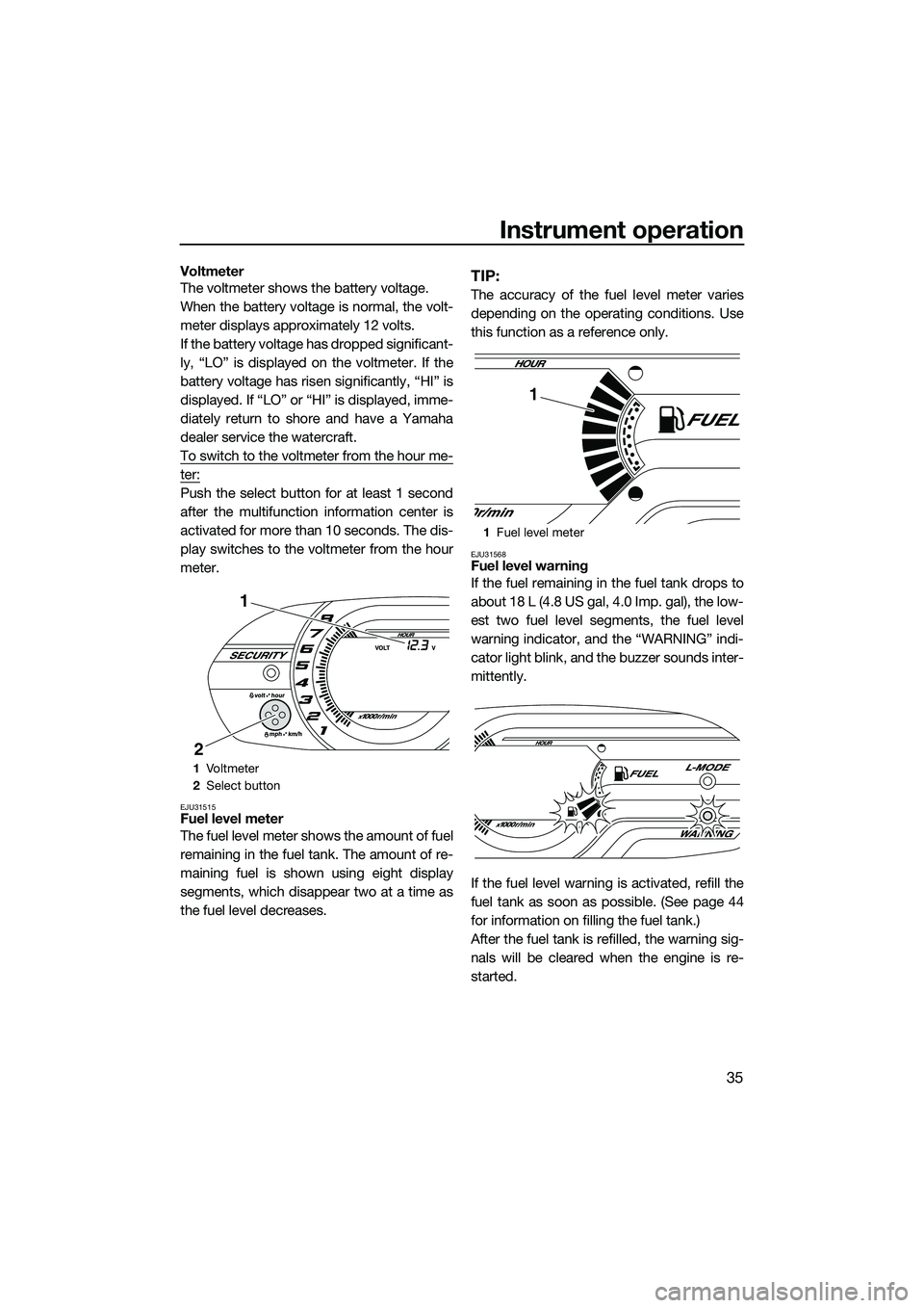
Voltmeter
The voltmeter shows the battery voltage.
When the battery voltage is normal, the volt-
meter displays approximately 12 volts.
If the battery voltage has dropped significant-
ly, “LO” is displayed on the voltmeter. If the
battery voltage has risen significantly, “HI” is
displayed. If “LO” or “HI” is displayed, imme-
diately return to shore and have a Yamaha
dealer service the watercraft.
To switch to the voltmeter from the hour me-
ter:
Push the select button for at least 1 second
after the multifunction information center is
activated for more than 10 seconds. The dis-
play switches to the voltmeter from the hour
meter.
EJU31515Fuel level meter
The fuel level meter shows the amount of fuel
remaining in the fuel tank. The amount of re-
maining fuel is shown using eight display
segments, which disappear two at a time as
the fuel level decreases.
TIP:
The accuracy of the fuel level meter varies
depending on the operating conditions. Use
this function as a reference only.
EJU31568Fuel level warning
If the fuel remaining in the fuel tank drops to
about 18 L (4.8 US gal, 4.0 Imp. gal), the low-
est two fuel level segments, the fuel level
warning indicator, and the “WARNING” indi-
cator light blink, and the buzzer sounds inter-
mittently.
If the fuel level warning is activated, refill the
fuel tank as soon as possible. (See page 44
for information on filling the fuel tank.)
After the fuel tank is refilled, the warning sig-
nals will be cleared when the engine is re-
started.
1Vo l t m et e r
2 Select button
1
2
1Fuel level meter
1
UF2M73E0.book Page 35 Friday, August 2, 2013 11:28 AM