check oil YAMAHA VXR 2014 Owners Manual
[x] Cancel search | Manufacturer: YAMAHA, Model Year: 2014, Model line: VXR, Model: YAMAHA VXR 2014Pages: 98, PDF Size: 3.98 MB
Page 5 of 98

Table of contents
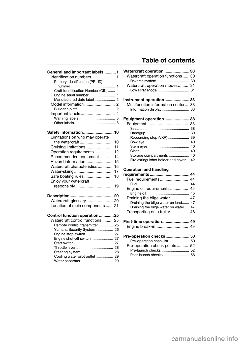
General and important labels ........... 1Identification numbers .................... 1
Primary Identification (PRI-ID)
number............................................ 1
Craft Identification Number (CIN) ....... 1
Engine serial number.......................... 1
Manufactured date label .................... 2
Model information ........................... 2
Builder’s plate .................................... 2
Important labels .............................. 4
Warning labels.................................... 5
Other labels ........................................ 8
Safety information ........................... 10 Limitations on who may operate the watercraft ............................. 10
Cruising limitations ........................ 11
Operation requirements ................ 12
Recommended equipment ........... 14
Hazard information........................ 15
Watercraft characteristics ............. 15
Water-skiing .................................. 17
Safe boating rules ......................... 18
Enjoy your watercraft responsibly ................................. 19
Description....................................... 20 Watercraft glossary ....................... 20
Location of main components ...... 21
Control function operation ............. 25 Watercraft control functions ......... 25
Remote control transmitter .............. 25
Yamaha Security System ................. 26
Engine stop switch .......................... 27
Engine shut-off switch .................... 27
Start switch ..................................... 27
Throttle lever .................................... 28
Steering system ............................... 28
Cooling water pilot outlet ................. 29
Water separator................................ 29
Watercraft operation ...................... 30Watercraft operation functions ..... 30
Reverse system ................................ 30
Watercraft operation modes ......... 31
Low RPM Mode ............................... 31
Instrument operation ...................... 33Multifunction information center ... 33
Information display ........................... 33
Equipment operation ...................... 38Equipment..................................... 38
Seat .................................................. 38
Handgrip........................................... 39
Reboarding step (VXR) ..................... 39
Bow eye............................................ 40
Stern eyes ........................................ 40
Cleat ................................................. 40
Storage compartments .................... 40
Fire extinguisher holder and cover ... 42
Operation and handling
requirements ................................... 44Fuel requirements ......................... 44
Fuel................................................... 44
Engine oil requirements ................ 45
Engine oil .......................................... 45
Draining the bilge water ................ 47
Draining the bilge water on land....... 47
Draining the bilge water on water .... 47
Transporting on a trailer................ 48
First-time operation ........................ 49 Engine break-in............................. 49
Pre-operation checks ..................... 50
Pre-operation checklist .................... 50
Pre-operation check points .......... 52
Pre-launch checks ........................... 52
Post-launch checks.......................... 58
UF2M73E0.book Page 1 Friday, August 2, 2013 11:28 AM
Page 39 of 98

Instrument operation
33
EJU41851
Multifunction information center
The multifunction information center displays
various watercraft information.
Multifunction information center initial op-
eration
When the multifunction information center is
activated, all of the display segments and the
“SECURITY” indicator light come on. After 2
seconds, the warning indicators in the infor-
mation display go off, and then the center
starts to operate normally.
TIP:
The “SECURITY” indicator light will go off
when the engine is started.
Multifunction information center standby
state
If the multifunction information center does
not receive any operation input within 25 sec-
onds after the engine stops, the center will
turn off and enter a standby state. When the
engine is started again, the displays return to
their state before the center turned off, and
then the center starts to operate normally.
EJU35025Information display
The information display shows watercraft op-
erating conditions.
EJU31504Speedometer
The speedometer shows the watercraft
speed against water.
By switching the display units, the speed can
be shown in kilometers per hour “km/h” or
miles per hour “mph”.
TIP:
“mph” is selected as the display unit at the
Yamaha factory.
1 “SECURITY” indicator light
2 Select button
3 Information display
4 “L-MODE” indicator light
5 “WARNING” indicator light
21345
1Tachometer
2 Speedometer
3 Hour meter/voltmeter
4 Fuel level meter
5 Check engine warning indicator
6 Engine overheat warning indicator
7 Oil pressure warning indicator
8 Fuel level warning indicator
1 Speedometer
1234
8765
1
UF2M73E0.book Page 33 Friday, August 2, 2013 11:28 AM
Page 42 of 98

Instrument operation
36
TIP:
Push the select button on the multifunction
information center to stop the buzzer.
EJU31627Oil pressure warning
If the oil pressure drops significantly, the oil
pressure warning indicator and the “WARN-
ING” indicator light blink, and the buzzer
sounds intermittently. At the same time, the
maximum engine speed is limited.
If the oil pressure warning is activated, imme-
diately reduce the engine speed, return to
shore, and then check the engine oil level.
(See page 45 for information on checking the
engine oil level.) If the oil level is sufficient,
have a Yamaha dealer check the watercraft.
TIP:
Push the select button on the multifunction
information center to stop the buzzer.
EJU3160AEngine overheat warning
If the engine temperature rises significantly,
the engine overheat warning indicator and
the “WARNING” indicator light blink, and the
buzzer sounds intermittently. Then, the en-
gine overheat warning indicator and the
“WARNING” indicator light stop blinking and
remain on, and the buzzer sounds continu-ously. At the same ti
me, the maximum engine
speed is limited.
If the engine overheat warning is activated,
immediately reduce the engine speed, return
to shore, and then make sure that water is
being discharged from the cooling water pilot
outlet while the engine is running. If there is
no discharge of water, stop the engine, and
then check the jet intake for clogging. (See
page 85 for information on the jet intake.)
NOTICE: If you cannot locate and correct
the cause of the overheating, consult a
Yamaha dealer. Continuing to operate at higher speeds could result in severe en-
gine damage.
[ECJ00042]
TIP:
Push the select button on the multifunction
information center to stop the buzzer.
UF2M73E0.book Page 36 Friday, August 2, 2013 11:28 AM
Page 51 of 98

Operation and handling requirements
45
(6) Stop filling when the fuel level reachesapproximately 50 mm (2 in) from the top
of the fuel tank. Do not overfill the fuel
tank. Because fuel expands when it
heats up, heat from the engine or the sun
can cause fuel to spill out of the fuel tank.
Do not leave the watercraft with a full
tank in direct sunlight.
(7) Wipe up any spilled fuel immediately with a dry cloth.
(8) Securely install the fuel filler cap by tight- ening it until it clicks.
(9) Securely install the seat in its original po- sition.
EJU40291
Engine oil requirementsEJU41871Engine oil
NOTICE
ECJ00282
Use only 4-stroke engine oil. Usage of 2-
stroke engine oil could result in severe en-
gine damage.
Checking the engine oil level
WARNING
EWJ00341
Engine oil is extremely hot immediately af-
ter the engine is turned off. Coming in con-
tact with or getting any engine oil on your
clothes could result in burns.
NOTICE
ECJ01002
Make sure that debris and water do not
enter the oil filler hole. Debris and water in
the engine oil can cause serious engine
damage.
To check the engine oil level:
(1) Place the watercraft in a precisely levelposition on land with the engine
stopped. If the engine was running, allow
the engine oil to settle by waiting 5 minu-
tes or more before checking the oil level.
(2) Remove the seat. (See page 38 for seat removal and installation procedures.)
Fuel tank capacity:
70 L (18.5 US gal, 15.4 Imp.gal)
1Approximately 50 mm (2 in) from top of the
fuel tank
1
Recommended engine oil type:
SAE 10W-30, 10W-40, 20W-40,
20W-50
Recommended engine oil grade: API SE,SF,SG,SH,SJ,SL
UF2M73E0.book Page 45 Friday, August 2, 2013 11:28 AM
Page 52 of 98

Operation and handling requirements
46
(3) Remove the dipstick and wipe it clean.
(4) Insert the dipstick back into the dipsticktube completely. Remove the dipstick
again and make sure that the engine oil
level is between the minimum and maxi-
mum level marks.
(5) If the engine oil level is significantly above the maximum level mark, consult
a Yamaha dealer. If the engine oil level is
below the minimum level mark, add en-
gine oil. (6) Loosen the engine oil filler cap and re-
move it.
(7) Slowly add engine oil.
TIP:
The difference between the minimum and
maximum level marks on the dipstick is equal
to approximately 1 L (1.06 US qt, 0.88 Imp.qt)
of engine oil.
(8) Wait approximately 5 minutes to allow the engine oil to settle, and then check
the engine oil level again.
(9) Repeat steps 3–8 until the engine oil is at the proper level.
(10) Securely install the engine oil filler cap by tightening it until it stops.
(11) Securely install the seat in its original po- sition.
1Dipstick
1 Maximum level mark
2 Minimum level mark
1
2
1
1Engine oil filler cap
1
UF2M73E0.book Page 46 Friday, August 2, 2013 11:28 AM
Page 55 of 98

First-time operation
49
EJU36666
Engine break-in
NOTICE
ECJ00432
Failure to perform the engine break-in
could result in reduced engine life or even
severe engine damage.
The engine break-in is essential to allow the
various components of the engine to wear
and polish themselves to the correct operat-
ing clearances. This ensures proper perfor-
mance and promotes longer component life.
To perform the engine break-in:
(1) Check the engine oil level. (See page 45for information on checking the engine
oil level.)
(2) Launch the watercraft and start the en- gine. (See page 60 for information on
starting the engine.)
(3) For the first 5 minutes, operate with the engine speed at 2000 r/min.
(4) For the next 30 minutes, operate with the engine speed below 5000 r/min.
(5) For the next 1 hour, operate with the en- gine speed below 6000 r/min.
After the engine break-in is complete, the wa-
tercraft can be operated normally.
UF2M73E0.book Page 49 Friday, August 2, 2013 11:28 AM
Page 56 of 98

Pre-operation checks
50
EJU31982
WARNING
EWJ00412
Failure to inspect or maintain the watercraft properly increases the possibility of an ac-
cident or damage to the watercraft. Do not operate the watercraft if you find any prob-
lem. If a problem cannot be corrected by the procedures provided in this manual, have
the watercraft inspected by a Yamaha dealer.
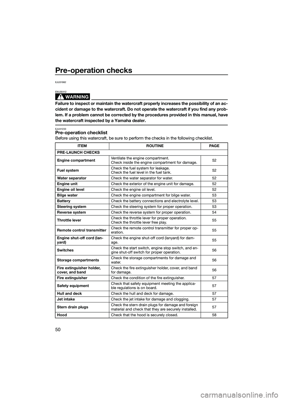
EJU41233Pre-operation checklist
Before using this watercraft, be sure to perform the checks in the following checklist.
ITEMROUTINEPAGE
PRE-LAUNCH CHECKS
Engine compartment Ventilate the engine compartment.
Check inside the engine compartment for damage.
52
Fuel system Check the fuel system for leakage.
Check the fuel level in the fuel tank.
52
Water separator Check the water separator for water. 52
Engine unit Check the exterior of the engine unit for damage. 52
Engine oil level Check the engine oil level. 52
Bilge water Check the engine compartment for bilge water. 53
Battery Check the battery connections and electrolyte level. 53
Steering system Check the steering system for proper operation. 53
Reverse system Check the reverse system for proper operation. 54
Throttle lever Check the throttle lever for proper operation.
Check the throttle lever free play.
55
Remote control transmitter Check the remote control transmitter for proper op-
eration.
55
Engine shut-off cord (lan-
yard) Check the engine shut-off cord (lanyard) for dam-
age.
55
Switches Check the start switch, engine stop switch, and en-
gine shut-off switch for proper operation.
56
Storage compartments Check the storage compartments for damage and
water.
56
Fire extinguisher holder,
cover, and band Check the fire extinguisher holder, cover, and band
for damage.
56
Fire extinguisher Check the condition of the fire extinguisher. 57
Safety equipment Check that safety equipment meeting the applica-
ble regulations is on board.
57
Hull and deck Check the hull and deck for damage. 57
Jet intake Check the jet intake for damage and clogging. 57
Stern drain plugs Check the stern drain plugs for damage and foreign
material and check that they are securely installed.
57
Hood Check that the hood is securely closed. 58
UF2M73E0.book Page 50 Friday, August 2, 2013 11:28 AM
Page 58 of 98

Pre-operation checks
52
EJU32282
Pre-operation check pointsEJU40546Pre-launch checks
Perform the pre-launch checks in the pre-op-
eration checklist while the watercraft is on
land.
To perform the pre-launch checks:
(1) Remove the seat. (See page 38 for seatremoval and installation procedures.)
(2) Perform the checks and make sure that there are no malfunctioning items or oth-
er problems.
(3) After completing these checks, securely install the seat in its original position.
EJU32334Engine compartment check
WARNING
EWJ00462
Failure to ventilate the engine compart-
ment could result in a fire or explosion. Do
not start the engine if there is a fuel leak.
Ventilate the engine compartment. Leave the
engine compartment open for a few minutes
to allow any fuel vapors to escape.
Make sure that there is no damage inside the
engine compartment.
EJU34215Fuel system checks
WARNING
EWJ00382
Leaking fuel can result in fire or explosion.
Check for fuel leakage regularly.
If any fuel leakage is found, the fuel sys-
tem must be repaired by a qualified me-
chanic. Improper repairs can make the
watercraft unsafe to operate.
Make sure that there is no damage, leakage,
or other problem in the fuel system.
Check:
Fuel filler cap and seal for damage
Fuel tank for damage and leakage
Fuel hoses and joints for damage and leak-
age
Fuel tank breather hose for damage and
leakage
EJU36875Fuel level check
Check the fuel level in the fuel tank.
Add fuel if necessary. (See page 44 for infor-
mation on filling the fuel tank.)
EJU32424Water separator check
Make sure that no water has collected in the
water separator. If water has collected in the
water separator, drain it. (See page 29 for in-
formation on draining the water separator.)
EJU40182Engine unit check
Check the exterior of the engine unit for dam-
age or other problem.
EJU36886Engine oil level check
Make sure that the engine oil level is between
the minimum and maxi mum level marks on
1Water separator
1
UF2M73E0.book Page 52 Friday, August 2, 2013 11:28 AM
Page 59 of 98

Pre-operation checks
53
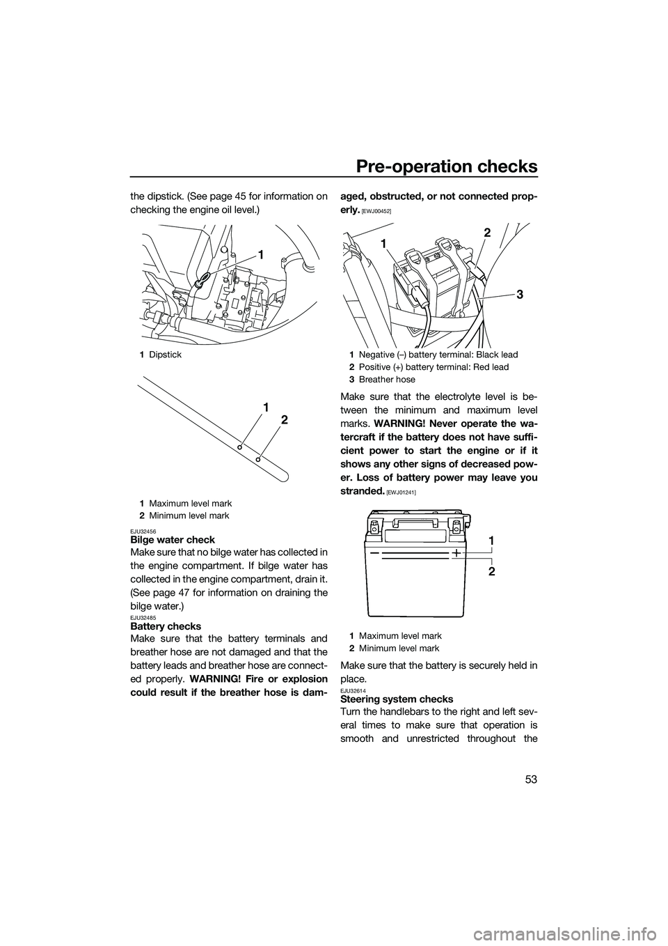
the dipstick. (See page 45 for information on
checking the engine oil level.)
EJU32456Bilge water check
Make sure that no bilge water has collected in
the engine compartment. If bilge water has
collected in the engine compartment, drain it.
(See page 47 for information on draining the
bilge water.)
EJU32485Battery checks
Make sure that the battery terminals and
breather hose are not damaged and that the
battery leads and breather hose are connect-
ed properly. WARNING! Fire or explosion
could result if the breather hose is dam- aged, obstructed, or not connected prop-
erly.
[EWJ00452]
Make sure that the electrolyte level is be-
tween the minimum and maximum level
marks.
WARNING! Never operate the wa-
tercraft if the battery does not have suffi-
cient power to start the engine or if it
shows any other signs of decreased pow-
er. Loss of battery power may leave you
stranded.
[EWJ01241]
Make sure that the battery is securely held in
place.
EJU32614Steering system checks
Turn the handlebars to the right and left sev-
eral times to make sure that operation is
smooth and unrestricted throughout the
1 Dipstick
1 Maximum level mark
2 Minimum level mark
1
2
1
1Negative (–) battery terminal: Black lead
2 Positive (+) battery terminal: Red lead
3 Breather hose
1 Maximum level mark
2 Minimum level mark
1 2
3
UF2M73E0.book Page 53 Friday, August 2, 2013 11:28 AM
Page 78 of 98

Care and storage
72
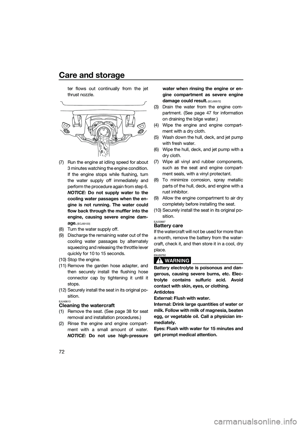
ter flows out continually from the jet
thrust nozzle.
(7) Run the engine at idling speed for about 3 minutes watching the engine condition.
If the engine stops while flushing, turn
the water supply off immediately and
perform the procedure again from step 6.
NOTICE: Do not supply water to the
cooling water passages when the en-
gine is not running. The water could
flow back through the muffler into the
engine, causing severe engine dam-
age.
[ECJ00123]
(8) Turn the water supply off.
(9) Discharge the remaining water out of the cooling water passages by alternately
squeezing and releasing the throttle lever
quickly for 10 to 15 seconds.
(10) Stop the engine.
(11) Remove the garden hose adapter, and then securely install the flushing hose
connector cap by tightening it until it
stops.
(12) Securely install the seat in its original po- sition.
EJU40613Cleaning the watercraft
(1) Remove the seat. (See page 38 for seatremoval and installation procedures.)
(2) Rinse the engine and engine compart- ment with a small amount of water.
NOTICE: Do not use high-pressure water when rinsing the engine or en-
gine compartment as severe engine
damage could result.
[ECJ00572]
(3) Drain the water from the engine com-
partment. (See page 47 for information
on draining the bilge water.)
(4) Wipe the engine and engine compart- ment with a dry cloth.
(5) Wash down the hull, deck, and jet pump with fresh water.
(6) Wipe the hull, deck, and jet pump with a dry cloth.
(7) Wipe all vinyl and rubber components, such as the seat and engine compart-
ment seals, with a vinyl protectant.
(8) To minimize corrosion, spray metallic parts of the hull, deck, and engine with a
rust inhibitor.
(9) Allow the engine compartment to air dry completely before installing the seat.
(10) Securely install the seat in its original po- sition.
EJU33687Battery care
If the watercraft will not be used for more than
a month, remove the battery from the water-
craft, check it, and then store it in a cool, dry
place.
WARNING
EWJ00792
Battery electrolyte is poisonous and dan-
gerous, causing severe burns, etc. Elec-
trolyte contains sulfuric acid. Avoid
contact with skin, eyes, or clothing.
Antidotes
External: Flush with water.
Internal: Drink large quantities of water or
milk. Follow with milk of magnesia, beaten
egg, or vegetable oil. Call a physician im-
mediately.
Eyes: Flush with water for 15 minutes and
get prompt medical attention.
UF2M73E0.book Page 72 Friday, August 2, 2013 11:28 AM