stop start YAMAHA VXR 2015 Owners Manual
[x] Cancel search | Manufacturer: YAMAHA, Model Year: 2015, Model line: VXR, Model: YAMAHA VXR 2015Pages: 108, PDF Size: 3.59 MB
Page 5 of 108

Table of contents
General and important labels ........... 1
Identification numbers .................... 1
Primary Identification (PRI-ID)
number............................................ 1
Craft Identification Number (CIN) ....... 1
Engine serial number.......................... 1
Manufactured date label .................... 2
Model information ........................... 2
Builder’s plate .................................... 2
Important labels .............................. 4
Warning labels.................................... 5
Other labels ........................................ 8
Safety information ........................... 10
Limitations on who may operate
the watercraft ............................. 10
Cruising limitations ........................ 11
Operation requirements ................ 12
Recommended equipment ........... 14
Hazard information........................ 15
Watercraft characteristics ............. 15
Wakeboarding and water-skiing ... 17
Safe boating rules ......................... 18
Enjoy your watercraft
responsibly ................................. 19
Description....................................... 20
Watercraft glossary ....................... 20
Location of main components ...... 21
Control function operation ............. 25
Watercraft control functions ......... 25
Remote control transmitter .............. 25
Yamaha Security System ................. 26
Engine stop switch .......................... 27
Engine shut-off switch .................... 27
Start switch ..................................... 27
Throttle lever .................................... 28
RiDE lever ......................................... 28
Steering system ............................... 28
Cooling water pilot outlet ................. 29
Water separator................................ 29
Watercraft operation ...................... 31
Watercraft operation functions ..... 31
Shift system...................................... 31
Electric trim system .......................... 33
Watercraft operation modes ......... 35
Low RPM Mode ............................... 35
Instrument operation ...................... 37
Multifunction information center ... 37
Information display ........................... 37
Hour meter ....................................... 41
Voltmeter .......................................... 41
Equipment operation ...................... 43
Equipment..................................... 43
Seats ................................................ 43
Handgrip........................................... 44
Reboarding step (VXR) ..................... 44
Bow eye............................................ 45
Stern eyes ........................................ 45
Cleat ................................................. 45
Storage compartments .................... 46
Fire extinguisher holder and cover ... 48
Operation and handling
requirements ................................... 50
Fuel requirements ......................... 50
Fuel................................................... 50
Engine oil requirements ................ 52
Engine oil .......................................... 52
Draining the bilge water ................ 54
Draining the bilge water on land....... 54
Draining the bilge water on water .... 54
Transporting on a trailer................ 55
First-time operation ........................ 56
Engine break-in............................. 56
Pre-operation checks ..................... 57
Pre-operation checklist .................... 57
Pre-operation check points .......... 59
Pre-launch checks ........................... 59
Post-launch checks.......................... 65
UF2W70E0.book Page 1 Tuesday, December 8, 2015 9:03 AM
Page 6 of 108

Table of contents
Operation ......................................... 68
Operating your watercraft ............. 68
Getting to know your watercraft ...... 68
Learning to operate your
watercraft ...................................... 68
Riding position ................................. 69
Launching the watercraft ................. 69
Starting the engine on water ............ 69
Stopping the engine ......................... 70
Leaving the watercraft...................... 70
Operating the watercraft .................. 70
Turning the watercraft ...................... 71
Stopping the watercraft ................... 72
Operating the watercraft in reverse
or neutral....................................... 73
Boarding the watercraft ................... 74
Starting off........................................ 76
Capsized watercraft ......................... 77
Beaching and docking the
watercraft ...................................... 78
Operating in weeded areas .............. 78
After removing the watercraft from
the water ....................................... 78
Care and storage............................. 80
Post-operation care ...................... 80
Flushing the cooling water
passages....................................... 80
Cleaning the watercraft .................... 81
Battery care ...................................... 81
Long-term storage ........................ 84
Cleaning ........................................... 84
Lubrication ....................................... 84
Rustproofing..................................... 84
Maintenance .................................... 85
Maintenance.................................. 85
Tool kit.............................................. 85
Removing and installing the engine
cover ............................................. 85
Periodic maintenance chart ............. 87
Engine oil and oil filter ...................... 89
Specifications .................................. 90
Specifications ............................... 90
Trouble recovery ............................. 91
Troubleshooting ............................ 91
Troubleshooting chart ...................... 91
Emergency procedures ................ 94
Cleaning the jet intake and
impeller ......................................... 94
Raising the reverse gate................... 95
Jumping the battery ......................... 95
Replacing the fuses .......................... 96
Towing the watercraft....................... 98
Submerged watercraft ..................... 98
Index............................................... 100
UF2W70E0.book Page 2 Tuesday, December 8, 2015 9:03 AM
Page 29 of 108
Description
23
13 12 4
35 9 10 9
7
6 8
1112
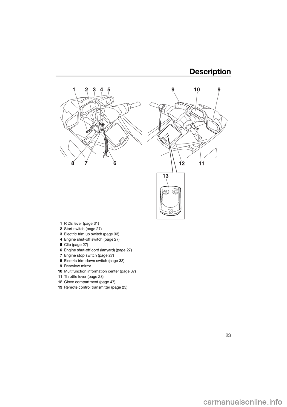
1RiDE lever (page 31)
2Start switch (page 27)
3Electric trim up switch (page 33)
4Engine shut-off switch (page 27)
5Clip (page 27)
6Engine shut-off cord (lanyard) (page 27)
7Engine stop switch (page 27)
8Electric trim down switch (page 33)
9Rearview mirror
10Multifunction information center (page 37)
11Throttle lever (page 28)
12Glove compartment (page 47)
13Remote control transmitter (page 25)
UF2W70E0.book Page 23 Tuesday, December 8, 2015 9:03 AM
Page 32 of 108
Control function operation
26
EJU31385Yamaha Security System
The Yamaha Security System functions to
help prevent unauthorized use or theft of the
watercraft. The lock and unlock modes of the
security system can be selected by operating
the remote control transmitter that is included
with this watercraft. The engine cannot be
started if the lock mode of the security sys-
tem is selected. The engine can only be start-
ed if the unlock mode is selected. (See page
25 for information on the remote control
transmitter.)
TIP:
The Yamaha Security System settings can
only be selected while the engine is stopped.
EJU36776Yamaha Security System settings
The Yamaha Security System settings will be
confirmed by the number of beeps when the
remote control transmitter is operated, and
by the “UNLOCK” indicator light of the multi-
function information center. (See page 37 for
information on the multifunction information
center.)
TIP:
The beeper sounds two times for the nor-
mal operation mode or three times for the
Low RPM Mode. (See page 35 for Low
RPM Mode activation procedures.)
If the remote control transmitter is operated
while the multifunction information centeris in the standby state, the center will per-
form the initial operation, and then the set-
ting is selected.
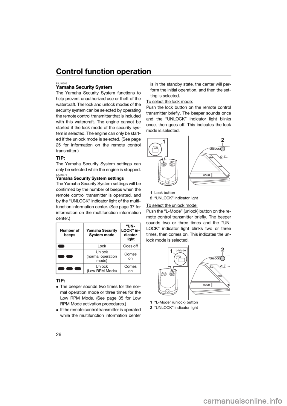
To select the lock mode:
Push the lock button on the remote control
transmitter briefly. The beeper sounds once
and the “UNLOCK” indicator light blinks
once, then goes off. This indicates the lock
mode is selected.
To select the unlock mode:
Push the “L-Mode” (unlock) button on the re-
mote control transmitter briefly. The beeper
sounds two or three times and the “UN-
LOCK” indicator light blinks two or three
times, then comes on. This indicates the un-
lock mode is selected.
Number of
beepsYamaha Security
System mode“UN-
LOCK” in-
dicator
light
Lock Goes off
Unlock
(normal operation
mode)Comes
on
Unlock
(Low RPM Mode)Comes
on
1Lock button
2“UNLOCK” indicator light
1“L-Mode” (unlock) button
2“UNLOCK” indicator light
21
2L-Mode1
UF2W70E0.book Page 26 Tuesday, December 8, 2015 9:03 AM
Page 33 of 108
Control function operation
27
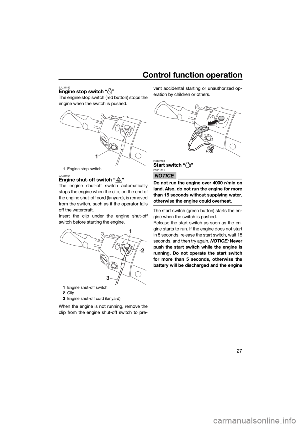
EJU31153Engine stop switch “ ”
The engine stop switch (red button) stops the
engine when the switch is pushed.
EJU31164Engine shut-off switch “ ”
The engine shut-off switch automatically
stops the engine when the clip, on the end of
the engine shut-off cord (lanyard), is removed
from the switch, such as if the operator falls
off the watercraft.
Insert the clip under the engine shut-off
switch before starting the engine.
When the engine is not running, remove the
clip from the engine shut-off switch to pre-vent accidental starting or unauthorized op-
eration by children or others.
EJU42323Start switch “ ”
NOTICE
ECJ01311
Do not run the engine over 4000 r/min on
land. Also, do not run the engine for more
than 15 seconds without supplying water,
otherwise the engine could overheat.
The start switch (green button) starts the en-
gine when the switch is pushed.
Release the start switch as soon as the en-
gine starts to run. If the engine does not start
in 5 seconds, release the start switch, wait 15
seconds, and then try again. NOTICE: Never
push the start switch while the engine is
running. Do not operate the start switch
for more than 5 seconds, otherwise the
battery will be discharged and the engine
1Engine stop switch
1Engine shut-off switch
2Clip
3Engine shut-off cord (lanyard)
1
1
2
3
UF2W70E0.book Page 27 Tuesday, December 8, 2015 9:03 AM
Page 34 of 108
![YAMAHA VXR 2015 Owners Manual Control function operation
28
will not start. Also, the starter motor could
be damaged.
[ECJ01041]
The engine will not start under any of the fol-
lowing conditions:
Lock mode of the Yamaha Securi YAMAHA VXR 2015 Owners Manual Control function operation
28
will not start. Also, the starter motor could
be damaged.
[ECJ01041]
The engine will not start under any of the fol-
lowing conditions:
Lock mode of the Yamaha Securi](/img/51/52198/w960_52198-33.png)
Control function operation
28
will not start. Also, the starter motor could
be damaged.
[ECJ01041]
The engine will not start under any of the fol-
lowing conditions:
Lock mode of the Yamaha Security System
has been selected. (See page 26 for
Yamaha Security System setting proce-
dures.)
Clip is removed from the engine shut-off
switch.
Throttle lever is squeezed.
Throttle lever is malfunctioning.
RiDE lever is squeezed.
RiDE lever is malfunctioning.EJU31212Throttle lever
The throttle lever increases the engine speed
when the lever is squeezed.
The throttle lever returns automatically to its
fully closed (idle) position when released.
EJU43341RiDE lever
When the RiDE lever is squeezed, the reverse
gate lowers and the watercraft starts moving
in reverse. If the watercraft is moving forward,
the watercraft gradually slows down until it
stops, and then the watercraft starts moving
in reverse.
When the RiDE lever is released, it automati-
cally returns to its fully closed (idle) position
and the reverse gate moves to the neutral po-
sition.
EJU31262Steering system
By turning the handlebars in the direction you
wish to travel, the angle of the jet thrust noz-
1Start switch
1Throttle lever
1
1
1RiDE lever
1
UF2W70E0.book Page 28 Tuesday, December 8, 2015 9:03 AM
Page 35 of 108
Control function operation
29
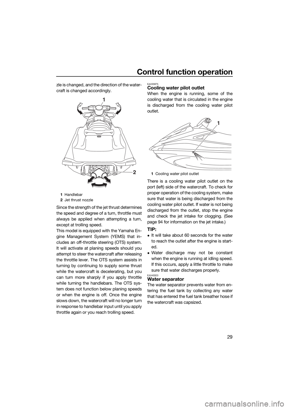
zle is changed, and the direction of the water-
craft is changed accordingly.
Since the strength of the jet thrust determines
the speed and degree of a turn, throttle must
always be applied when attempting a turn,
except at trolling speed.
This model is equipped with the Yamaha En-
gine Management System (YEMS) that in-
cludes an off-throttle steering (OTS) system.
It will activate at planing speeds should you
attempt to steer the watercraft after releasing
the throttle lever. The OTS system assists in
turning by continuing to supply some thrust
while the watercraft is decelerating, but you
can turn more sharply if you apply throttle
while turning the handlebars. The OTS sys-
tem does not function below planing speeds
or when the engine is off. Once the engine
slows down, the watercraft will no longer turn
in response to handlebar input until you apply
throttle again or you reach trolling speed.EJU35975Cooling water pilot outlet
When the engine is running, some of the
cooling water that is circulated in the engine
is discharged from the cooling water pilot
outlet.
There is a cooling water pilot outlet on the
port (left) side of the watercraft. To check for
proper operation of the cooling system, make
sure that water is being discharged from the
cooling water pilot outlet. If water is not being
discharged from the outlet, stop the engine
and check the jet intake for clogging. (See
page 94 for information on the jet intake.)
TIP:
It will take about 60 seconds for the water
to reach the outlet after the engine is start-
ed.
Water discharge may not be constant
when the engine is running at idling speed.
If this occurs, apply a little throttle to make
sure that water discharges properly.
EJU40323Water separator
The water separator prevents water from en-
tering the fuel tank by collecting any water
that has entered the fuel tank breather hose if
the watercraft was capsized.
1Handlebar
2Jet thrust nozzle
1
21Cooling water pilot outlet
1
UF2W70E0.book Page 29 Tuesday, December 8, 2015 9:03 AM
Page 43 of 108
Instrument operation
37
EJU43760
Multifunction information
center
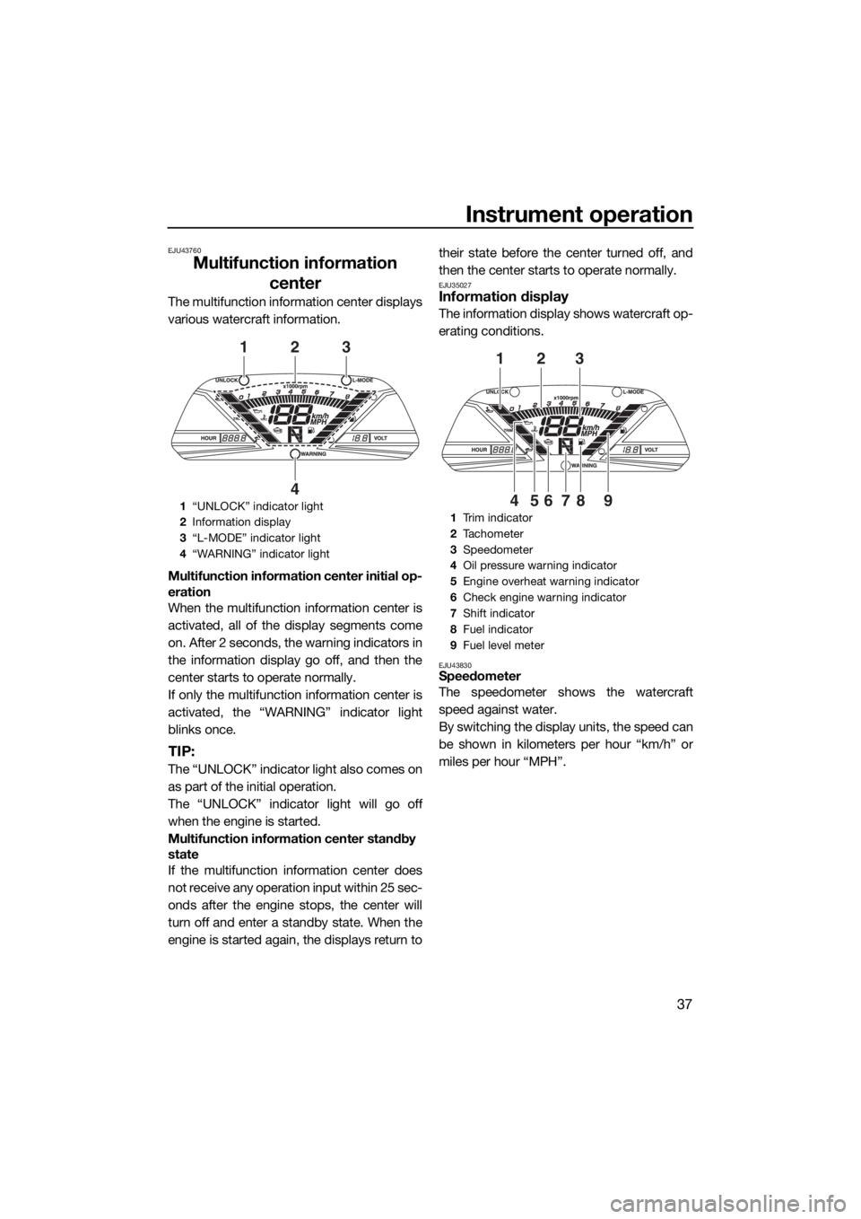
The multifunction information center displays
various watercraft information.
Multifunction information center initial op-
eration
When the multifunction information center is
activated, all of the display segments come
on. After 2 seconds, the warning indicators in
the information display go off, and then the
center starts to operate normally.
If only the multifunction information center is
activated, the “WARNING” indicator light
blinks once.
TIP:
The “UNLOCK” indicator light also comes on
as part of the initial operation.
The “UNLOCK” indicator light will go off
when the engine is started.
Multifunction information center standby
state
If the multifunction information center does
not receive any operation input within 25 sec-
onds after the engine stops, the center will
turn off and enter a standby state. When the
engine is started again, the displays return totheir state before the center turned off, and
then the center starts to operate normally.
EJU35027Information display
The information display shows watercraft op-
erating conditions.
EJU43830Speedometer
The speedometer shows the watercraft
speed against water.
By switching the display units, the speed can
be shown in kilometers per hour “km/h” or
miles per hour “MPH”.
1“UNLOCK” indicator light
2Information display
3“L-MODE” indicator light
4“WARNING” indicator light
123
4
1Trim indicator
2Tachometer
3Speedometer
4Oil pressure warning indicator
5Engine overheat warning indicator
6Check engine warning indicator
7Shift indicator
8Fuel indicator
9Fuel level meter
213
456879
UF2W70E0.book Page 37 Tuesday, December 8, 2015 9:03 AM
Page 44 of 108
Instrument operation
38
TIP:
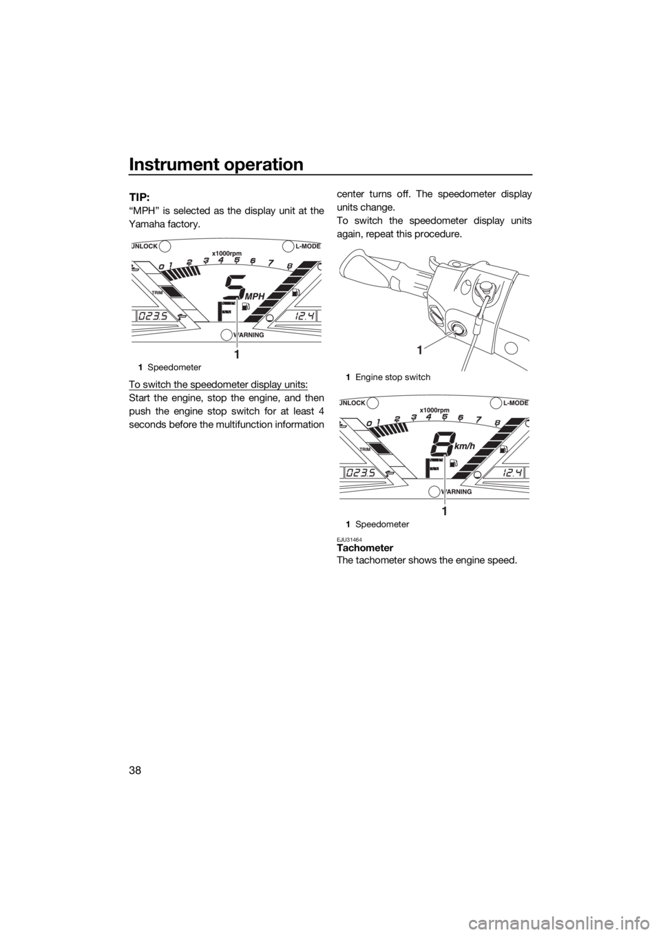
“MPH” is selected as the display unit at the
Yamaha factory.
To switch the speedometer display units:
Start the engine, stop the engine, and then
push the engine stop switch for at least 4
seconds before the multifunction informationcenter turns off. The speedometer display
units change.
To switch the speedometer display units
again, repeat this procedure.
EJU31464Tachometer
The tachometer shows the engine speed.
1Speedometer
1
1Engine stop switch
1Speedometer
1
1
UF2W70E0.book Page 38 Tuesday, December 8, 2015 9:03 AM
Page 46 of 108
Instrument operation
40
TIP:
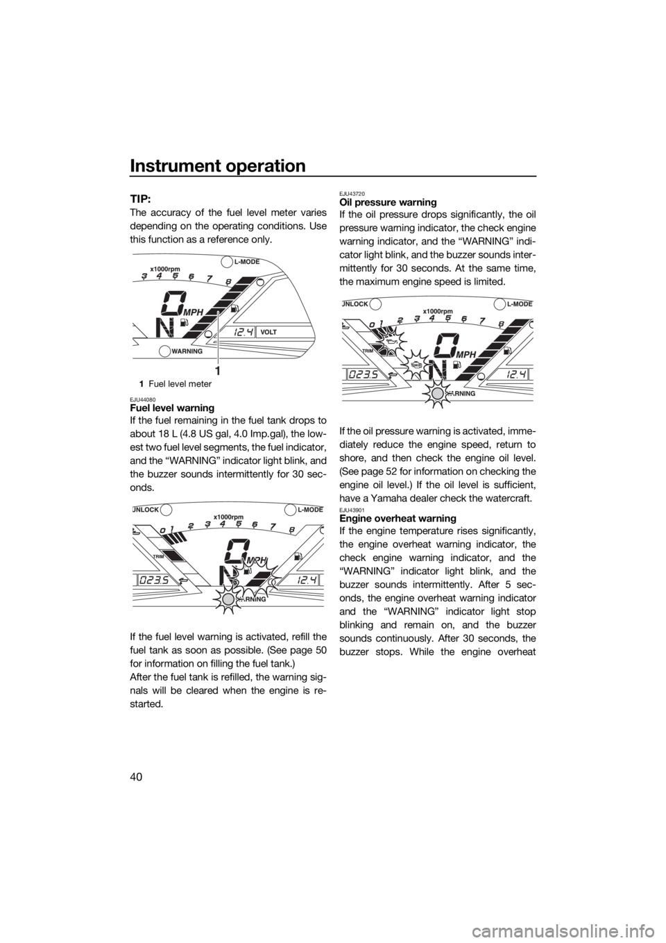
The accuracy of the fuel level meter varies
depending on the operating conditions. Use
this function as a reference only.
EJU44080Fuel level warning
If the fuel remaining in the fuel tank drops to
about 18 L (4.8 US gal, 4.0 Imp.gal), the low-
est two fuel level segments, the fuel indicator,
and the “WARNING” indicator light blink, and
the buzzer sounds intermittently for 30 sec-
onds.
If the fuel level warning is activated, refill the
fuel tank as soon as possible. (See page 50
for information on filling the fuel tank.)
After the fuel tank is refilled, the warning sig-
nals will be cleared when the engine is re-
started.
EJU43720Oil pressure warning
If the oil pressure drops significantly, the oil
pressure warning indicator, the check engine
warning indicator, and the “WARNING” indi-
cator light blink, and the buzzer sounds inter-
mittently for 30 seconds. At the same time,
the maximum engine speed is limited.
If the oil pressure warning is activated, imme-
diately reduce the engine speed, return to
shore, and then check the engine oil level.
(See page 52 for information on checking the
engine oil level.) If the oil level is sufficient,
have a Yamaha dealer check the watercraft.
EJU43901Engine overheat warning
If the engine temperature rises significantly,
the engine overheat warning indicator, the
check engine warning indicator, and the
“WARNING” indicator light blink, and the
buzzer sounds intermittently. After 5 sec-
onds, the engine overheat warning indicator
and the “WARNING” indicator light stop
blinking and remain on, and the buzzer
sounds continuously. After 30 seconds, the
buzzer stops. While the engine overheat
1Fuel level meter
1
UF2W70E0.book Page 40 Tuesday, December 8, 2015 9:03 AM