engine YAMAHA WOLVERINE 2015 Service Manual
[x] Cancel search | Manufacturer: YAMAHA, Model Year: 2015, Model line: WOLVERINE, Model: YAMAHA WOLVERINE 2015Pages: 186, PDF Size: 4.22 MB
Page 132 of 186
8-20
8
15. Turn the engine off, wait at least 10 min-utes, and then check the oil level and cor-
rect it if necessary.
16. Install the rubber cover.
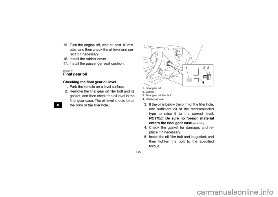
17. Install the passenger seat cushion.EBU32370Final gear oilChecking the final gear oil level 1. Park the vehicle on a level surface.
2. Remove the final gear oil filler bolt and its gasket, and then check the oil level in the
final gear case. The oil level should be at
the brim of the filler hole. 3. If the oil is below the brim of the filler hole,
add sufficient oil of the recommended
type to raise it to the correct level.
NOTICE: Be sure no foreign material
enters the final gear case.
[ECB00422]
4. Check the gasket for damage, and re- place it if necessary.
5. Install the oil filler bolt and its gasket, and then tighten the bolt to the specified
torque.1. Final gear oil
2. Gasket
3. Final gear oil filler bolt
4. Correct oil level
24
3
1
U2MB7AE0.book Page 20 Thursday, January 29, 2015 3:42 PM
Page 136 of 186
8-24
8
8. Check for oil leakage. If oil leakage isfound, check for the cause.EBU33660CoolantThe coolant level should be checked before
each ride. In addition, the coolant must be
changed at the intervals specified in the peri-
odic maintenance and lubrication chart.
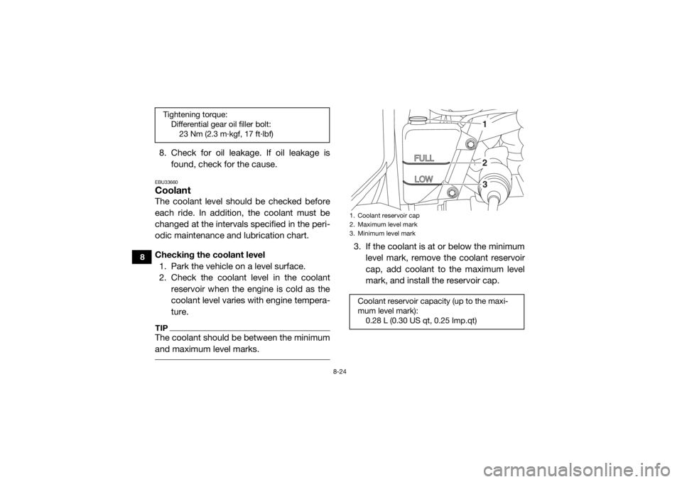
Checking the coolant level1. Park the vehicle on a level surface.
2. Check the coolant level in the coolant reservoir when the engine is cold as the
coolant level varies with engine tempera-
ture.TIPThe coolant should be between the minimum
and maximum level marks.
3. If the coolant is at or below the minimum
level mark, remove the coolant reservoir
cap, add coolant to the maximum level
mark, and install the reservoir cap.
Tightening torque:Differential gear oil filler bolt:23 Nm (2.3 m·kgf, 17 ft·lbf)
1. Coolant reservoir cap
2. Maximum level mark
3. Minimum level markCoolant reservoir capacity (up to the maxi-
mum level mark):0.28 L (0.30 US qt, 0.25 Imp.qt)
123
U2MB7AE0.book Page 24 Thursday, January 29, 2015 3:42 PM
Page 137 of 186
8-25
8
Changing the coolant
WARNING
EWB01891Wait for the engine and radiator to cool be-
fore removing the radiator cap. You could
be burned by hot fluid and steam blown
out under pressure. Always place a thick
rag over the cap when opening. Allow any
remaining pressure to escape before com-
pletely removing the cap. 1. Park the vehicle on a level surface.
2. Remove the hood. (See page 8-10 forhood removal and installation proce-
dures.)
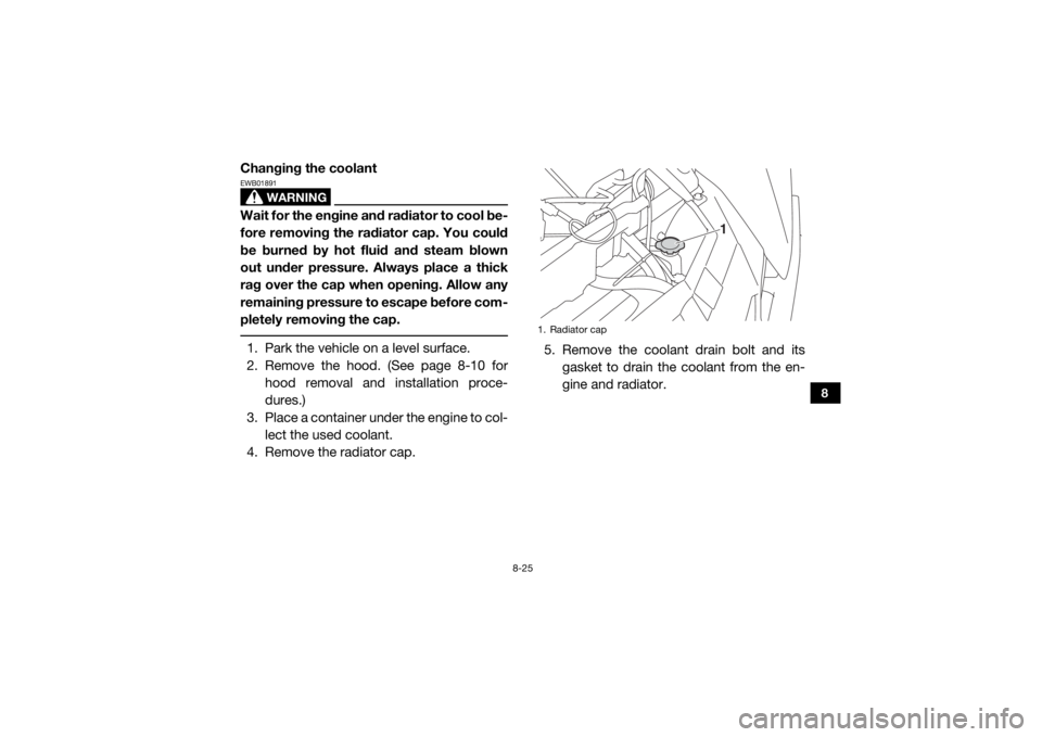
3. Place a container under the engine to col- lect the used coolant.
4. Remove the radiator cap. 5. Remove the coolant drain bolt and its
gasket to drain the coolant from the en-
gine and radiator.
1. Radiator cap
1
U2MB7AE0.book Page 25 Thursday, January 29, 2015 3:42 PM
Page 139 of 186
8-27
8
11. Connect the coolant reservoir hose.
12. Pour the recommended coolant into theradiator until it is full.
13. Pour the recommended coolant into the
reservoir to the maximum level mark, and
then install the reservoir cap.NOTICEECB02190Mix antifreeze with distilled water only.
However, if distilled water is not available,
soft water may be used for refilling. Do not
use hard water or salt water since they are
harmful to the engine.
14. Remove the right panel and right rearpanel. (See page 8-11 for right panel and
right rear panel removal and installation
procedures.)
15. Loosen the water pump air bleed bolt, without removing it, to allow all of the air
to escape from the air bleed bolt hole.
Tightening torque:Coolant drain bolt:8 Nm (0.8 m·kgf, 5.8 ft·lbf)
Antifreeze/water mixture ratio: 1:1
Recommended antifreeze: High-quality ethylene glycol antifreeze con-
taining corrosion inhibitors for aluminum
engines
Coolant quantity: Radiator (including all routes):2.85 L (3.01 US qt, 2.51 Imp.qt)
Coolant reservoir (up to the maximum level
mark): 0.28 L (0.30 US qt, 0.25 Imp.qt)
U2MB7AE0.book Page 27 Thursday, January 29, 2015 3:42 PM
Page 140 of 186
8-28
8
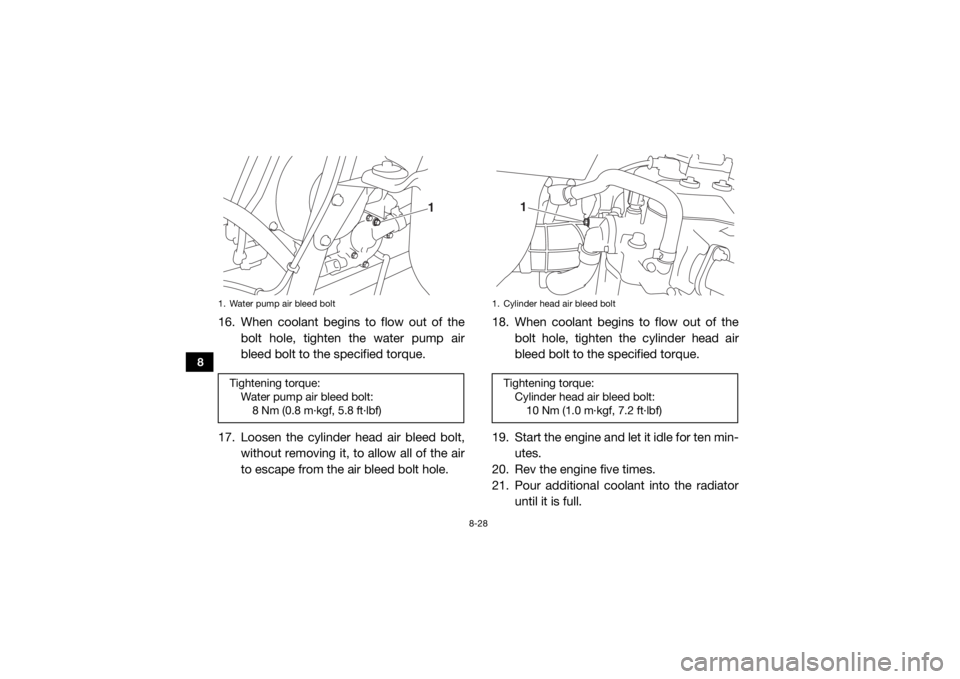
16. When coolant begins to flow out of thebolt hole, tighten the water pump air
bleed bolt to the specified torque.
17. Loosen the cylinder head air bleed bolt, without removing it, to allow all of the air
to escape from the air bleed bolt hole. 18. When coolant begins to flow out of the
bolt hole, tighten the cylinder head air
bleed bolt to the specified torque.
19. Start the engine and let it idle for ten min- utes.
20. Rev the engine five times.
21. Pour additional coolant into the radiator until it is full.1. Water pump air bleed boltTightening torque:Water pump air bleed bolt:8 Nm (0.8 m·kgf, 5.8 ft·lbf)
1
1. Cylinder head air bleed boltTightening torque:Cylinder head air bleed bolt:10 Nm (1.0 m·kgf, 7.2 ft·lbf)
1
U2MB7AE0.book Page 28 Thursday, January 29, 2015 3:42 PM
Page 141 of 186
8-29
8
22. Stop the engine and allow it to cool. If thecoolant level has dropped after the en-
gine has cooled, add sufficient coolant
until it reaches the top of the radiator, and
then install the radiator cap.
23. Check the coolant level in the reservoir. If necessary, remove the coolant reservoir
cap, add coolant to the maximum level
mark, and then install the cap.
24. Start the engine, and then check for cool- ant leakage.TIPIf any leakage is found, have a Yamaha dealer
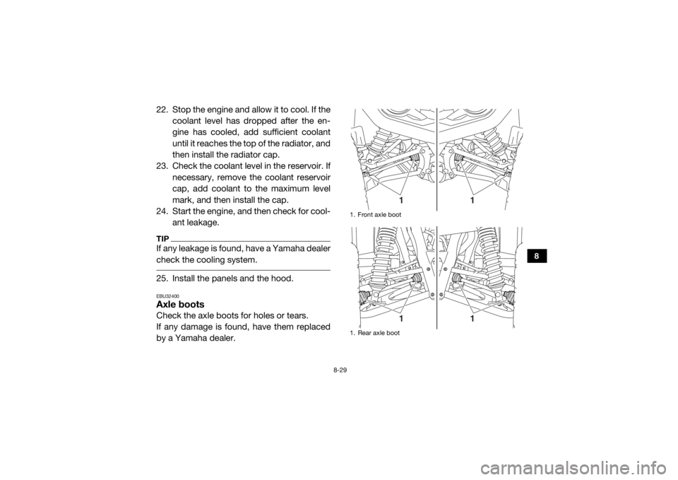
check the cooling system. 25. Install the panels and the hood.EBU32400Axle bootsCheck the axle boots for holes or tears.
If any damage is found, have them replaced
by a Yamaha dealer.
1. Front axle boot
1. Rear axle boot
1
1
1
1
U2MB7AE0.book Page 29 Thursday, January 29, 2015 3:42 PM
Page 142 of 186
8-30
8
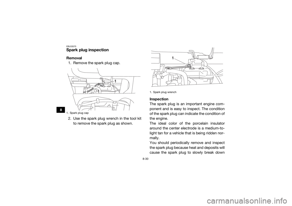
EBU33570Spark plug inspectionRemoval1. Remove the spark plug cap.
2. Use the spark plug wrench in the tool kit to remove the spark plug as shown. Inspection
The spark plug is an important engine com-
ponent and is easy to inspect. The condition
of the spark plug can indicate the condition of
the engine.
The ideal color of the porcelain insulator
around the center electrode is a medium-to-
light tan for a vehicle that is being ridden nor-
mally.
You should periodically remove and inspect
the spark plug because heat and deposits will
cause the spark plug to slowly break down1. Spark plug cap
1
1. Spark plug wrench
1
U2MB7AE0.book Page 30 Thursday, January 29, 2015 3:42 PM
Page 144 of 186
8-32
8
EBU33580Cleaning the air filter elementThe air filter element should be cleaned every
20–40 hours. It should be cleaned and lubri-
cated more often if the vehicle is operated in
extremely dusty areas. Each time air filter ele-
ment maintenance is performed, check the air
inlet to the air filter case for obstructions.
Check the air filter element rubber joint to the
throttle body and manifold fittings for an air-
tight seal. Tighten all fittings securely to avoid
the possibility of unfiltered air entering the en-
gine.NOTICEECB02270Never operate the engine with the air filter
element removed. Doing so would allow
unfiltered air to enter, causing rapid en-
gine wear and possible engine damage.
Additionally, the fuel injection system
would be affected, resulting in poor engine
performance and possible overheating.
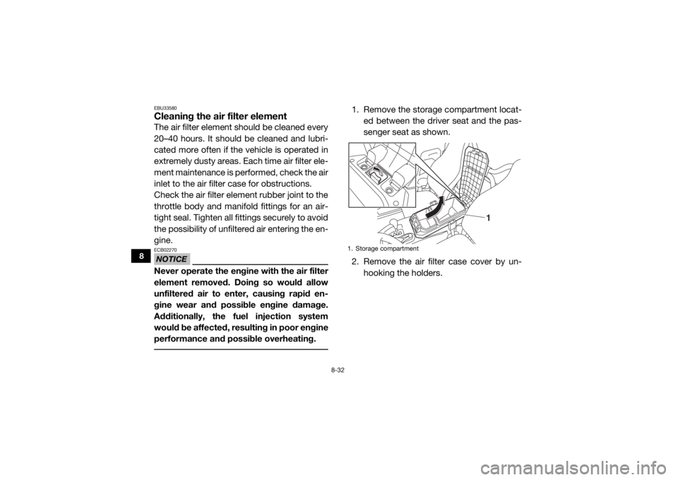
1. Remove the storage compartment locat-ed between the driver seat and the pas-
senger seat as shown.
2. Remove the air filter case cover by un- hooking the holders.1. Storage compartment
1
U2MB7AE0.book Page 32 Thursday, January 29, 2015 3:42 PM
Page 148 of 186
8-36
8
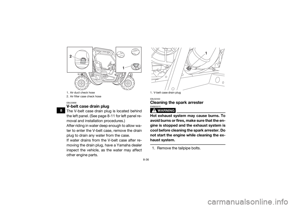
EBU33690V-belt case drain plugThe V-belt case drain plug is located behind
the left panel. (See page 8-11 for left panel re-
moval and installation procedures.)
After riding in water deep enough to allow wa-
ter to enter the V-belt case, remove the drain
plug to drain any water from the case.
If water drains from the V-belt case after re-
moving the drain plug, have a Yamaha dealer
inspect the vehicle, as the water may affect
other engine parts.
EBU32450Cleaning the spark arrester
WARNING
EWB03370Hot exhaust system may cause burns. To
avoid burns or fires, make sure that the en-
gine is stopped and the exhaust system is
cool before cleaning the spark arrester. Do
not start the engine while cleaning the ex-
haust system. 1. Remove the tailpipe bolts.
1. Air duct check hose
2. Air filter case check hose2
1
1. V-belt case drain plug
1
U2MB7AE0.book Page 36 Thursday, January 29, 2015 3:42 PM
Page 150 of 186
8-38
8
EBU32460Valve clearanceThe correct valve clearance changes with
use, resulting in improper fuel/air supply or
engine noise. To prevent this, the valve clear-
ance must be adjusted regularly. This adjust-
ment however, should be left to a
professional Yamaha service technician.EBU32470BrakesReplacement of brake components requires
professional knowledge. Brake service
should be performed by a Yamaha dealer.
WARNING
EWB02572Operating with improperly serviced or ad-
justed brakes could lead to a loss in brak-
ing ability and an accident.
EBU32480Checking the front and rear brake padsEach brake pad is provided with wear indica-
tor grooves, which allow you to check the
brake pad wear without having to disassem-
ble the brake. To check the brake pad wear,
check the wear indicator grooves. If a brake
pad has worn to the point that the wear indi-
cator grooves have almost disappeared, have
a Yamaha dealer replace the brake pads as a
set.
The wheels need to be removed to check the
brake pads. (See pages 8-44, 8-46 for wheel
removal and installation procedures.)
U2MB7AE0.book Page 38 Thursday, January 29, 2015 3:42 PM