engine coolant YAMAHA WOLVERINE 2018 Owners Manual
[x] Cancel search | Manufacturer: YAMAHA, Model Year: 2018, Model line: WOLVERINE, Model: YAMAHA WOLVERINE 2018Pages: 188, PDF Size: 5.4 MB
Page 6 of 188

EBU31120
CONTENTS
LOCATION OF THE WARNING AND
SPECIFICATION LABELS ....................... 1-1
SAFETY INFORMATION ......................... 2-1
DESCRIPTION......................................... 3-1Left view ............................................... 3-1
Right view ............................................. 3-2
Controls and instruments ..................... 3-3
INSTRUMENT AND CONTROL
FUNCTIONS............................................ 4-1 Main switch .......................................... 4-1
Indicator lights and warning lights ....... 4-2
Multi-function meter unit ...................... 4-6
Light switch ........................................ 4-11
On–Command drive knob “2WD/4WD/DIFF LOCK” .................. 4-11
Horn switch ....................................... 4-12
Accelerator pedal ............................... 4-12
Brake pedal ........................................ 4-13 Parking brake lever ............................ 4-13
Drive select lever ................................ 4-14
Fuel tank cap...................................... 4-14
Doors .................................................. 4-14
Seats .................................................. 4-15
Adjusting the driver seat position....... 4-16
Seat belts ........................................... 4-17
Glove compartment ........................... 4-18
Storage compartments ...................... 4-18
Cup holders ........................................ 4-20
Cargo bed .......................................... 4-20
Front shock absorbers ....................... 4-22
Rear shock absorbers ........................ 4-27
Trailer hitch bracket and receiver....... 4-32
Auxiliary DC jack ................................ 4-33
FOR YOUR SAFETY –
PRE-OPERATION CHECKS.................... 5-1 Front and rear brakes ........................... 5-3
Fuel....................................................... 5-3
Engine oil.............................................. 5-5
Coolant ................................................. 5-6
Final gear.............................................. 5-6UB3D7AE0.book Page 1 Tuesday, November 7, 2017 9:38 AM
Page 7 of 188

Differential gear .................................... 5-6
Accelerator pedal ................................. 5-6
Seat belts ............................................. 5-7
Passenger handhold ............................ 5-7
Steering ................................................ 5-7
Fittings and fasteners ........................... 5-7
Instruments, lights and switches .......... 5-8
Control cables ...................................... 5-8
Tires ...................................................... 5-8
OPERATION ............................................ 6-1 Engine break-in .................................... 6-1
Starting the engine ............................... 6-2
Drive select lever operation and reverse driving .................................... 6-3
On-Command drive knob..................... 6-5
Parking ................................................. 6-7
Loading................................................. 6-7
BASIC GUIDE FOR SAFE USE .............. 7-1 KNOW YOUR VEHICLE........................ 7-1
LEARNING TO OPERATE YOUR
VEHICLE ........................................... 7-12 PERIODIC MAINTENANCE AND
ADJUSTMENT .........................................8-1
Owner’s Manual and tool kit .................8-2
Maintenance charts ..............................8-4
Hood ...................................................8-10
Panels .................................................8-11
Engine oil and oil filter cartridge .........8-14
Final gear oil .......................................8-20
Differential gear oil ..............................8-22
Coolant ...............................................8-25
Axle boots ...........................................8-29
Spark plug inspection .........................8-30
Cleaning the air filter element .............8-32
Air filter check hoses ..........................8-36
V-belt case drain plug.........................8-37
Cleaning the spark arrester ................8-37
Valve clearance...................................8-39
Brakes.................................................8-39
Checking the front and rear brake pads ..................................................8-39
Checking the brake fluid level ............8-40
Brake fluid replacement ......................8-41
Checking the brake pedal...................8-42
UB3D7AE0.book Page 2 Tuesday, November 7, 2017 9:38 AM
Page 37 of 188

3-2
3
EBU31190Right view
10
9
4
118
3
4
5,6
1
7
2
1. Spark arrester
2. Passenger seat belt
3. Engine oil dipstick
4. Storage compartment
5. Battery
6. Fuses
7. Headlight
8. Coolant reservoir
9. Passenger seat
10.Fuel tank cap
11.Oil filter cartridgeUB3D7AE0.book Page 2 Tuesday, November 7, 2017 9:38 AM
Page 40 of 188

4-2
4
EBU31268Indicator lights and warning lights
EBU31270Low-range indicator light “L”
This indicator light comes on when the drive
select lever is in the “L” position.EBU31280High-range indicator light “H”
This indicator light comes on when the drive
select lever is in the “H” position.
1. Differential gear lock indicator light “DIFF. LOCK”
2. Low-range indicator light “L”
3. High-range indicator light “H”
4. Neutral indicator light “N”
5. Reverse indicator light “R”
6. Parking brake indicator light “ ”
7. Drivetrain icon “ / ”
8. Engine trouble warning light “ ”
9. Coolant temperature warning light “ ”
10.Electric Power Steering warning light “EPS”356421
7
8109
1. Helmet indicator light “ ”
2. Seat belt indicator light “ ”
21
UB3D7AE0.book Page 2 Tuesday, November 7, 2017 9:38 AM
Page 42 of 188
4-4
4
When the On–Command drive knob is set
to “DIFF LOCK” or “4WD”, the drivetrain
icon will flash until the differential has
locked or unlocked. Turn the steering wheel
back and forth or drive slowly to help the
differential gear lock to engage or disen-
gage. EBU31333Coolant temperature warning light “ ”
This light comes on to warn that the coolant
temperature is too hot. If the light comes on
during operation, stop the vehicle as soon as
it is safe to do so and allow the engine to cool
down for about 10 minutes. (See page 8-60.)TIPIf you continue to drive the vehicle while the
engine is overheating, a buzzer will sound. NOTICEECB03460Continuous use while this warning light is
on will damage the engine.
The electrical circuit of the warning light can
be checked by turning the key to “ ” (on). If
the warning light does not come on initially
when the key is turned to “ ” (on), or if the
warning light remains on, have a Yamaha
dealer check the electrical circuit.EBU31341Engine trouble warning light “ ”
This warning light comes on or flashes if a
problem is detected in the electrical circuit
monitoring the engine. When this occurs, the
display will indicate an error code (see page
4-10). Have a Yamaha dealer check the self-
diagnosis system.
The electrical circuit of the warning light can
be checked by turning the key to “ ” (on). If
the warning light does not come on initially
when the key is turned to “ ” (on), or if the
warning light remains on, have a Yamaha
dealer check the vehicle.
UB3D7AE0.book Page 4 Tuesday, November 7, 2017 9:38 AM
Page 78 of 188
5-6
5
NOTICEECB00301In order to prevent cl utch slippage (since
the engine oil also lubricates the clutch),
do not mix any chemical additives. Do
not use oils with a diesel specification of
“CD” or oils of a higher quality than
specified. In addition, do not use oils la-
beled “ENERGY CONSERVING II” or
higher.
Make sure that no foreign material en-
ters the crankcase. EBU31761CoolantCheck the coolant level in the reservoir and
replenish if necessary. (See page 8-25.)
EBU36020Final gearMake sure there is no oil leaking from the final
gear case.EBU36030Differential gearMake sure there is no oil leaking from the dif-
ferential gear case.EBU31791Accelerator pedalBefore starting the engine, confirm that the
accelerator pedal operates correctly. It
should depress smoothly and spring back to
the idle position when released. Also check
the accelerator pedal for excessive free play.
If the accelerator pedal is not in correct work-
ing order, have the vehicle inspected before
starting off.
Recommended engine oil type and quantity:
See page 10-1.
UB3D7AE0.book Page 6 Tuesday, November 7, 2017 9:38 AM
Page 84 of 188
6-2
6
10–20 hours:
Avoid prolonged operation above three-quar-
ter throttle.
After break-in:
The vehicle may now be operated normally.EBU33081Starting the engine1. Turn the key to “ ” (on).NOTICEECB02291The coolant temperature warning light and
engine trouble warning light should come
on, then go off.
The EPS warning light should come on,
then go off when the engine is started.
To avoid possible damage, do not operate
the vehicle if a warning light does not work
as described above. 2. Apply the brake pedal.
3. Shift the drive select lever into the neutralposition.
When the drive select lever is in the
neutral position, the neutral indicator
light should come on. If the neutral indi-
cator light does not come on, ask a
Yamaha dealer to inspect the electric
circuit.
The engine can be started in any gear if
the brake pedal is applied. However, it
is recommended to shift into neutral
before starting the engine.
4. With your foot off the accelerator pedal,
start the engine by turning the key to “ ”
(start).
If the engine fails to start, release the key, and
then try starting it again. Wait a few seconds
before the next attempt. Each attempt should
be as short as possible, to preserve battery
energy. NOTICE: Do not crank the engine
more than 5 seconds on each attempt, or
starter damage could occur. Wait at least
5 seconds between each operation of the
electric starter to let it cool.
[ECB02140]
UB3D7AE0.book Page 2 Tuesday, November 7, 2017 9:38 AM
Page 119 of 188

8-6
8
EBU32114General maintenance and lubricationNO. ITEMROUTINE INITIAL
EVERY
Whichev- er comes first month 1 3 6 6 12
km
(mi) 320
(200) 1200
(750) 2400
(1500) 2400
(1500) 4800
(3000)
hours 20 75 150 150 300
1 *Cooling system • Check coolant leakage.
• Repair if necessary.
√√√√√
• Change coolant. Every 2 years
2 Air filter element •Clean.
• Replace if necessary. Every 20–40 hours (more often in
wet or dusty areas)
3Engine oil • Change (warm engine before draining). √√√√
4 Engine oil filter
cartridge • Replace.
√√√
5 Final gear oil • Check oil level.
√√√√√
• Change. √√
6 Differential gear
oil • Check oil level.
√√√√√
• Change. √√
7 *Front brake • Check operation/brake pad wear/fluid leak-
age.
• Correct if necessary. Replace pads if worn to the limit. √√√√√
UB3D7AE0.book Page 6 Tuesday, November 7, 2017 9:38 AM
Page 138 of 188
8-25
8
EBU33661CoolantThe coolant level should be checked regular-
ly. In addition, the coolant must be changed
at the intervals specified in the periodic main-
tenance chart.TIPIf genuine Yamaha coolant is not available,
use an ethylene glycol antifreeze containing
corrosion inhibitors for aluminum engines and
mix with distilled water at a 1:1 ratio.
NOTICEECB02190Mix antifreeze with distilled water only.
However, if distilled water is not available,
soft water may be used for refilling. Do not
use hard water or salt water since they are
harmful to the engine. To check the coolant level1. Park the vehicle on a level surface.
2. Wait for the engine to cool for an accurate reading.
3. Look the coolant level in the coolant res- ervoir.
Recommended coolant:YAMALUBE coolant
Coolant quantity: Coolant reservoir (up to full level):0.28 L (0.30 US qt, 0.25 Imp.qt)
Radiator (including all routes): 2.85 L (3.01 US qt, 2.51 Imp.qt)
UB3D7AE0.book Page 25 Tuesday, November 7, 2017 9:38 AM
Page 139 of 188
8-26
8
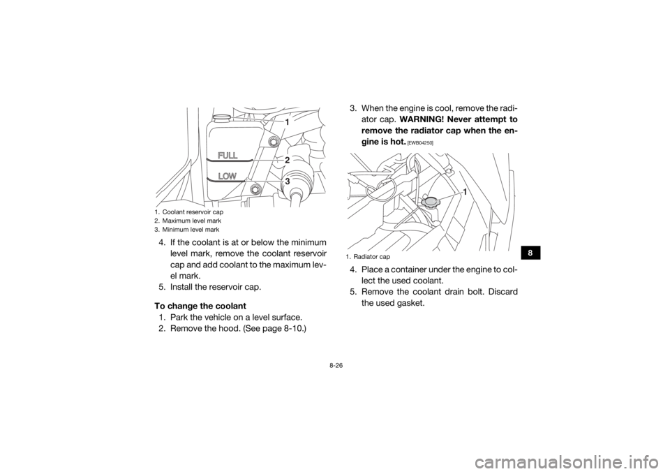
4. If the coolant is at or below the minimumlevel mark, remove the coolant reservoir
cap and add coolant to the maximum lev-
el mark.
5. Install the reservoir cap.
To change the coolant 1. Park the vehicle on a level surface.
2. Remove the hood. (See page 8-10.) 3. When the engine is cool, remove the radi-
ator cap. WARNING! Never attempt to
remove the radiator cap when the en-
gine is hot.
[EWB04250]
4. Place a container under the engine to col- lect the used coolant.
5. Remove the coolant drain bolt. Discard the used gasket.
1. Coolant reservoir cap
2. Maximum level mark
3. Minimum level mark
123
1. Radiator cap
1
UB3D7AE0.book Page 26 Tuesday, November 7, 2017 9:38 AM