light YAMAHA WOLVERINE 400 2004 Owner's Manual
[x] Cancel search | Manufacturer: YAMAHA, Model Year: 2004, Model line: WOLVERINE 400, Model: YAMAHA WOLVERINE 400 2004Pages: 422, PDF Size: 17.51 MB
Page 288 of 422

8-35 1. O-ring
1. Joint torique
1. Junta tórica
1. Torque wrench
1. Clé dynamométrique
1. Llave de apriete
7. Apply a light coat of engine oil to the O-ring of
the new oil filter cartridge.NOTE:_ Make sure the O-ring is seated properly. _8. Install the new oil filter cartridge with an oil fil-
ter wrench, and then tighten it to the specified
torque with a torque wrench.
9. Install panel E.
10. Install the engine oil drain bolt, and then tight-
en it to the specified torque. Tightening torque:
Oil filter cartridge:
17 Nm (1.7 m·kgf)
Tightening torque:
Engine oil drain bolt:
23 Nm (2.3 m·kgf)
U5TE61.book Page 35 Tuesday, May 6, 2003 4:40 PM
Page 318 of 422
8-65
Inspection
The spark plug is an important engine component
and is easy to inspect. The condition of the spark
plug can indicate the condition of the engine.
The ideal color on the white insulator around the
center electrode is a medium-to-light tan color for a
ATV that is being ridden normally.
Do not attempt to diagnose such problems your-
self.
Instead, take the ATV to a Yamaha dealer. You
should periodically remove and inspect the spark
plug because heat and deposits will cause the
spark plug to slowly break down and erode. If elec-
trode erosion becomes excessive, or if carbon and
other deposits are excessive, you should replace
the spark plug with the specified plug.
Specified spark plug:
DR8EA (NGK)
U5TE61.book Page 65 Tuesday, May 6, 2003 4:40 PM
Page 356 of 422
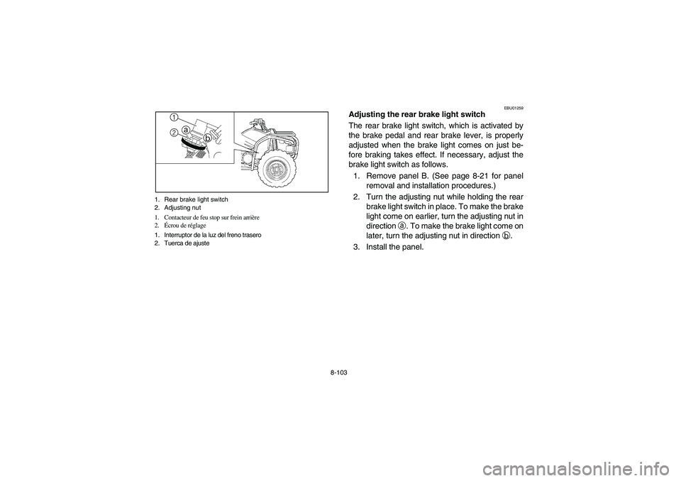
8-103 1. Rear brake light switch
2. Adjusting nut
1. Contacteur de feu stop sur frein arrière
2.Écrou de réglage
1. Interruptor de la luz del freno trasero
2. Tuerca de ajuste
EBU01259
Adjusting the rear brake light switch
The rear brake light switch, which is activated by
the brake pedal and rear brake lever, is properly
adjusted when the brake light comes on just be-
fore braking takes effect. If necessary, adjust the
brake light switch as follows.
1. Remove panel B. (See page 8-21 for panel
removal and installation procedures.)
2. Turn the adjusting nut while holding the rear
brake light switch in place. To make the brake
light come on earlier, turn the adjusting nut in
direction
a. To make the brake light come on
later, turn the adjusting nut in direction
b.
3. Install the panel.
U5TE61.book Page 103 Tuesday, May 6, 2003 4:40 PM
Page 374 of 422
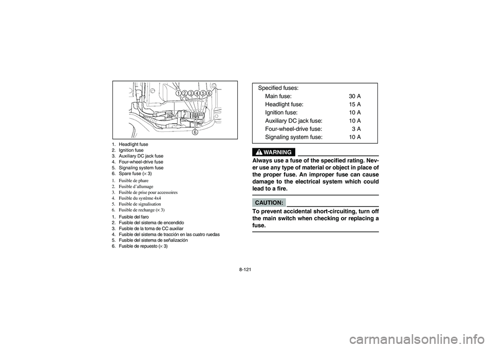
8-121 1. Headlight fuse
2. Ignition fuse
3. Auxiliary DC jack fuse
4. Four-wheel-drive fuse
5. Signaling system fuse
6. Spare fuse (× 3)
1. Fusible de phare
2. Fusible d’allumage
3. Fusible de prise pour accessoires
4. Fusible du système 4x4
5. Fusible de signalisation
6. Fusible de rechange (× 3)
1. Fusible del faro
2. Fusible del sistema de encendido
3. Fusible de la toma de CC auxiliar
4. Fusible del sistema de tracción en las cuatro ruedas
5. Fusible del sistema de señalización
6. Fusible de repuesto (× 3)
WARNING
_ Always use a fuse of the specified rating. Nev-
er use any type of material or object in place of
the proper fuse. An improper fuse can cause
damage to the electrical system which could
lead to a fire. _CAUTION:_ To prevent accidental short-circuiting, turn off
the main switch when checking or replacing a
fuse. _
Specified fuses:
Main fuse: 30 A
Headlight fuse: 15 A
Ignition fuse: 10 A
Auxiliary DC jack fuse: 10 A
Four-wheel-drive fuse: 3 A
Signaling system fuse: 10 A
U5TE61.book Page 121 Tuesday, May 6, 2003 4:40 PM
Page 376 of 422

8-123 1. Headlight bulb holder cover
1. Cache de la fixation de l’ampoule de phare
1. Cubierta del portabombillas de la bombilla del faro
1. Headlight bulb holder
1. Fixation d’ampoule
1. Porta bombillas del faro
EBU13230
Replacing a headlight bulb
If a headlight bulb burns out, replace it as follows.
1. Remove the bulb holder cover at the rear of
the headlight by pulling it off.
2. Remove the headlight bulb holder by turning
it counterclockwise.
U5TE61.book Page 123 Tuesday, May 6, 2003 4:40 PM
Page 378 of 422

8-125 1. Do not touch the glass part of the bulb.
1. Ne pas toucher le verre de l’ampoule.
1. No tocar la parte de cristal de la bombilla.
3. Remove the defective bulb by pushing it in
and turning it counterclockwise.
WARNING
_ A headlight bulb is hot when it is on and imme-
diately after it is turned off. Wait for the bulb to
cool before touching or removing it. You can
be burned or a fire could start if the bulb touch-
es something flammable. _4. Insert a new headlight bulb into the bulb hold-
er, push it in, and then turn the bulb clockwise
until it stops.CAUTION:_ Do not touch the glass part of the headlight
bulb to keep it free from oil, otherwise the
transparency of the glass, the luminosity of the
bulb, and the bulb life will be adversely affect-
ed. Thoroughly clean off any dirt and finger-
prints on the headlight bulb using a cloth
moistened with alcohol or thinner. _5. Install the bulb holder by turning it clockwise.
6. Install the bulb holder cover at the rear of the
headlight.
U5TE61.book Page 125 Tuesday, May 6, 2003 4:40 PM
Page 380 of 422
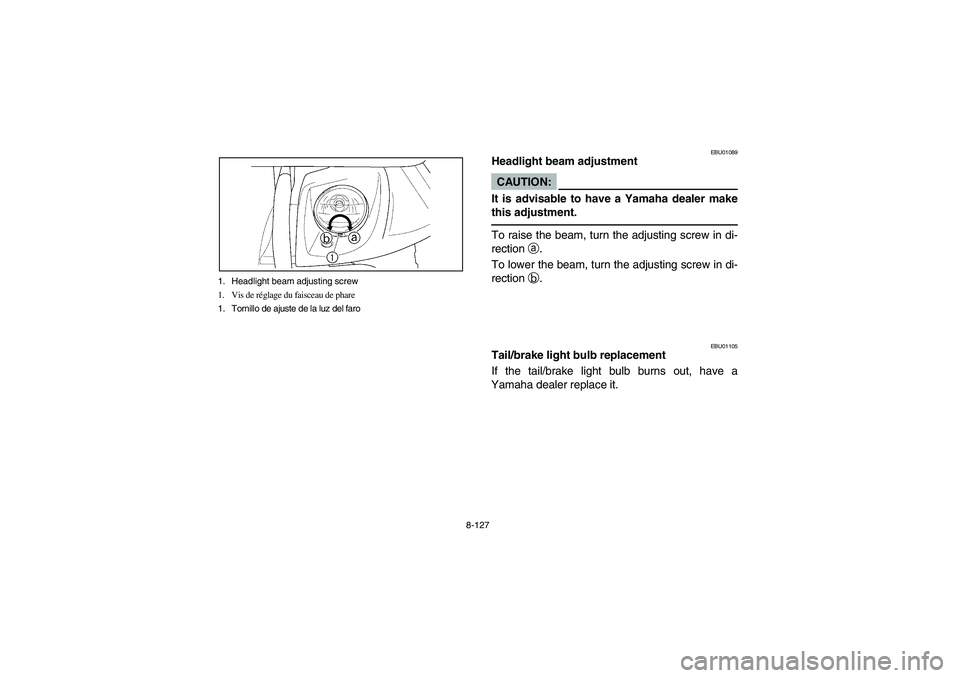
8-127 1. Headlight beam adjusting screw
1. Vis de réglage du faisceau de phare
1. Tornillo de ajuste de la luz del faro
EBU01089
Headlight beam adjustmentCAUTION:_ It is advisable to have a Yamaha dealer make
this adjustment. _To raise the beam, turn the adjusting screw in di-
rection
a.
To lower the beam, turn the adjusting screw in di-
rection
b.
EBU01105
Tail/brake light bulb replacement
If the tail/brake light bulb burns out, have a
Yamaha dealer replace it.
U5TE61.book Page 127 Tuesday, May 6, 2003 4:40 PM
Page 382 of 422
8-129
EBU00413
Troubleshooting
Although Yamaha machines receive a rigid in-
spection before shipment from the factory, trouble
may occur during operation.
Any problem in the fuel, compression, or ignition
systems can cause poor starting and loss of pow-
er. The troubleshooting chart describes a quick,
easy procedure for making checks. If your ma-
chine requires any repair, take it to a Yamaha
dealer.
The skilled technicians at a Yamaha dealership
have the tools, experience, and know-how to prop-
erly service your machine. Use only genuine
Yamaha parts on your machine. Imitation parts
may look like Yamaha parts, but they are often in-
ferior. Consequently, they have a shorter service
life and can lead to expensive repair bills.
WARNING
Do not smoke when checking the fuel system.
Fuel can ignite or explode, causing severe in-
jury or property damage. Make sure there are
no open flames or sparks in the area, including
pilot lights from water heaters or furnaces.
U5TE61.book Page 129 Tuesday, May 6, 2003 4:40 PM
Page 398 of 422
9-9
5. Tie a plastic bag over the exhaust pipe outlet
to prevent moisture from entering.
6. If storing in a humid or salt-air atmosphere,
coat all exposed metal surfaces with a light
film of oil. Do not apply oil to any rubber parts
or the seat cover.
7. Remove the battery and charge it. Store it in
a dry place and recharge it once a month. Do
not store the battery in an excessively warm
or cold place (less than 0°C or more than
30°C).NOTE:Make any necessary repairs before storing the
machine.
U5TE61.book Page 9 Tuesday, May 6, 2003 4:40 PM
Page 404 of 422
10-5
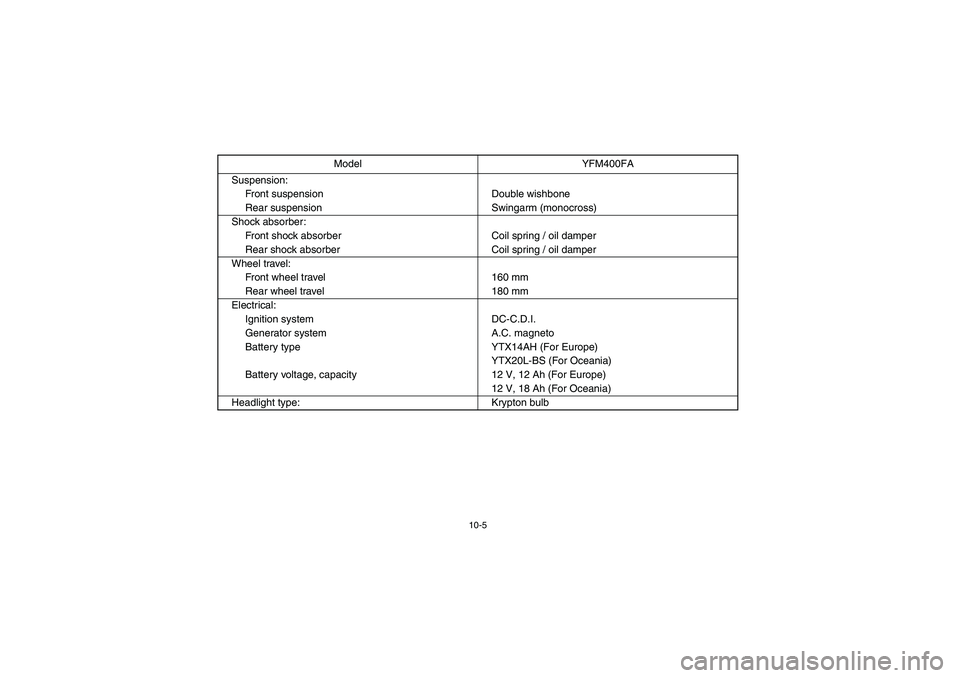
Suspension:
Front suspension Double wishbone
Rear suspension Swingarm (monocross)
Shock absorber:
Front shock absorber Coil spring / oil damper
Rear shock absorber Coil spring / oil damper
Wheel travel:
Front wheel travel 160 mm
Rear wheel travel 180 mm
Electrical:
Ignition system DC-C.D.I.
Generator system A.C. magneto
Battery type YTX14AH (For Europe)
YTX20L-BS (For Oceania)
Battery voltage, capacity 12 V, 12 Ah (For Europe)
12 V, 18 Ah (For Oceania)
Headlight type: Krypton bulbModel YFM400FA
U5TE61.book Page 5 Tuesday, May 6, 2003 4:40 PM