BRAKE LIGHT FUSE YAMAHA WOLVERINE 450 2007 Owners Manual
[x] Cancel search | Manufacturer: YAMAHA, Model Year: 2007, Model line: WOLVERINE 450, Model: YAMAHA WOLVERINE 450 2007Pages: 142, PDF Size: 12.27 MB
Page 10 of 142
Adjusting the rear brake lever free play
and checking the brake pedal position ... 8-40
Axle boots ................................................ 8-42
Brake light switches ................................. 8-43
Checking and lubricating the cables ........ 8-43
Checking and lubricating the front and
rear brake levers .................................... 8-44
Checking and lubricating the brake
pedal ...................................................... 8-44
Checking the wheel bearings ................... 8-45
Lubricating the drive shaft universal
joint ......................................................... 8-45
Lubricating the steering shaft ................... 8-45
Battery ...................................................... 8-45
Replacing a fuse ...................................... 8-47
Replacing a headlight bulb ....................... 8-49
Adjusting a headlight beam ...................... 8-51
Replacing the tail/brake light bulb ............ 8-51
Removing a wheel .................................... 8-52
Installing a wheel ...................................... 8-53
Troubleshooting ....................................... 8-54
Troubleshooting charts ............................. 8-55
CLEANING AND STORAGE .......................... 9-1
Cleaning ..................................................... 9-1
Storage ....................................................... 9-2SPECIFICATIONS .......................................10-1
CONSUMER INFORMATION.......................11-1
Identification numbers ...............................11-1
U3C261E0.book Page 3 Thursday, June 29, 2006 4:15 PM
Page 18 of 142
3-1
3
EBU17680
DESCRIPTION
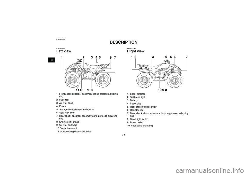
EBU17690Left view
EBU17700Right view
1. Front shock absorber assembly spring preload adjusting
ring
2. Fuel cock
3. Air filter case
4. Fuses
5. Storage compartment and tool kit
6. Seat lock lever
7. Rear shock absorber assembly spring preload adjusting
ring
8. Engine oil filler cap
9. Oil filter cartridge
10.Coolant reservoir
11.V-belt cooling duct check hose
1. Spark arrester
2. Tail/brake light
3. Battery
4. Spark plug
5. Rear brake fluid reservoir
6. Radiator cap
7. Front shock absorber assembly spring preload adjusting
ring
8. Brake light switch
9. Brake pedal
10.V-belt case drain plug
U3C261E0.book Page 1 Thursday, June 29, 2006 4:15 PM
Page 137 of 142
10-4
10
Front suspension:Type:
Double wishbone
Spring/shock absorber type:
Coil spring/oil damper
Wheel travel:
160 mm (6.3 in)Rear suspension:Type:
Swingarm
Spring/shock absorber type:
Coil spring/oil damper
Wheel travel:
180 mm (7.1 in)Electrical system:Ignition system:
DC. CDI
Charging system:
AC magnetoBattery:Model:
YTX20L-BS
Voltage, capacity:
12 V, 18.0 AhHeadlight:Bulb type:
Krypton bulbBulb voltage, wattage x quantity:Headlight:
12 V, 30.0/30.0 W × 2Tail/brake light:
12 V, 5.0/21.0 W × 1
Neutral indicator light:
LED
Reverse indicator light:
LED
Coolant temperature warning light:
LED
Park indicator light:
LED
On-Command four-wheel-drive indicator:
LCD
Fuses:Main fuse:
30.0 A
Headlight fuse:
15.0 A
Signaling system fuse:
10.0 A
Ignition fuse:
10.0 A
Auxiliary DC jack fuse:
10.0 A
Backup fuse:
10.0 A
Four-wheel-drive motor fuse:
3.0 A
U3C261E0.book Page 4 Thursday, June 29, 2006 4:15 PM
Page 140 of 142
INDEX
AAccessories and loading ................................................ 6-6
Air filter element, cleaning ............................................ 8-30
Axle boots .................................................................... 8-42BBattery .......................................................................... 8-45
Brake fluid, changing .................................................... 8-39
Brake fluid level, checking ............................................ 8-38
Brake lever free play and brake pedal position (rear),
adjusting and checking .............................................. 8-40
Brake lever free play, checking the front ...................... 8-40
Brake lever, front ............................................................ 4-7
Brake levers, checking and lubricating ......................... 8-44
Brake light switches ..................................................... 8-43
Brake pads, checking the front and rear ...................... 8-37
Brake pedal and rear brake lever ................................... 4-7
Brake pedal, checking and lubricating ......................... 8-44
Brakes, front and rear .................................................... 5-4CCables, checking and lubricating ................................. 8-43
Carburetor, adjusting .................................................... 8-34
Chassis fasteners ........................................................... 5-7
Cleaning ......................................................................... 9-1
Coolant .................................................................. 5-3, 8-25
Coolant temperature warning light ................................. 4-2
Cowlings and panels, removing and installing ............... 8-8DDifferential gear oil ......................................................... 5-3Differential gear oil, changing ....................................... 8-23
Drive select lever ............................................................ 4-8
Drive select lever and driving in reverse ........................ 6-3
Drive select lever safety system cable, adjusting ......... 8-37
Drive shaft universal joint, lubricating ........................... 8-45
EEngine break-in .............................................................. 6-5
Engine, cold start ........................................................... 6-1
Engine idling speed ...................................................... 8-35
Engine oil ....................................................................... 5-3
Engine oil and oil filter cartridge ................................... 8-16
Engine, starting a warm ................................................. 6-3
Engine stop switch ......................................................... 4-4FFinal gear oil .......................................................... 5-3, 8-21
Four-wheel-drive indicator .............................................. 4-2
Fuel ......................................................................... 4-9, 5-3
Fuel cock ...................................................................... 4-10
Fuel tank cap .................................................................. 4-8
Fuses, replacing ........................................................... 8-47HHandlebar switches ........................................................ 4-4
Headlight beam, adjusting ............................................ 8-51
Headlight bulb, replacing .............................................. 8-49IIdentification numbers .................................................. 11-1
Indicator lights and warning light .................................... 4-2
Instruments, lights and switches .................................... 5-7
U3C261E0.book Page 1 Thursday, June 29, 2006 4:15 PM