checking oil YAMAHA WR 250F 2003 Betriebsanleitungen (in German)
[x] Cancel search | Manufacturer: YAMAHA, Model Year: 2003, Model line: WR 250F, Model: YAMAHA WR 250F 2003Pages: 860, PDF-Größe: 35.16 MB
Page 36 of 860
1 - 11
GEN
INFO
SPECIAL TOOLS
SPECIAL TOOLS
The proper special tools are necessary for complete and accurate tune-up and assembly. Using the correct special tool
will help prevent damage caused by the use of improper tools or improvised techniques. The shape and part number used
for the special tool differ by country, so two types are provided. Refer to the list provided to avoid errors when placing an
order.
NOTE:For U.S.A. and Canada, use part number starting with “YM-”, “YU-” or “ACC-”.
For others, use part number starting with “90890-”.
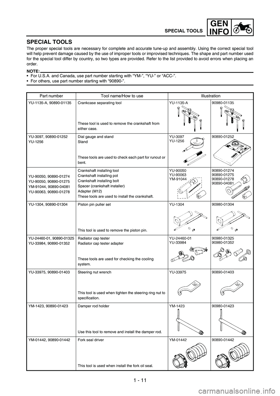
Part number Tool name/How to use Illustration
YU-1135-A, 90890-01135 Crankcase separating tool
These tool is used to remove the crankshaft from
either case.
YU-3097, 90890-01252
YU-1256Dial gauge and stand
Stand
These tools are used to check each part for runout or
bent.
YU-90050, 90890-01274
YU-90050, 90890-01275
YM-91044, 90890-04081
YU-90063, 90890-01278Crankshaft installing tool
Crankshaft installing pot
Crankshaft installing bolt
Spacer (crankshaft installer)
Adapter (M12)
These tools are used to install the crankshaft.
YU-1304, 90890-01304 Piston pin puller set
This tool is used to remove the piston pin.
YU-24460-01, 90890-01325
YU-33984, 90890-01352Radiator cap tester
Radiator cap tester adapter
These tools are used for checking the cooling
system.
YU-33975, 90890-01403 Steering nut wrench
This tool is used when tighten the steering ring nut to
specification.
YM-1423, 90890-01423 Damper rod holder
Use this tool to remove and install the damper rod.
YM-01442, 90890-01442 Fork seal driver
This tool is used when install the fork oil seal.
Page 37 of 860

1 - 12
GEN
INFO
SPECIAL TOOLS
YU-3112-C, 90890-03112 Pocket tester
Use this tool to inspect the coil resistance, output
voltage and amperage.
YU-8036-B
90890-03113Inductive tachometer
Engine tachometer
This tool is needed for observing engine rpm.
YM-33277-A, 90890-03141 Timing light
This tool is necessary for checking ignition timing.
YM-4019, 90890-04019 Valve spring compressor
This tool is needed to remove and install the valve
assemblies.
YM-91042, 90890-04086 Clutch holding tool
This tool is used to hold the clutch when removing or
installing the clutch boss securing nut.
YM-4111, 90890-04111
YM-4116, 90890-04116Valve guide remover
Intake 4.0 mm (0.16 in)
Exhaust 4.5 mm (0.18 in)
This tool is needed to remove and install the valve
guide.
YM-4112, 90890-04112
YM-4117, 90890-04117Valve guide installer
Intake 4.0 mm (0.16 in)
Exhaust 4.5 mm (0.18 in)
This tool is needed to install the valve guide.
YM-4113, 90890-04113
YM-4118, 90890-04118Valve guide reamer
Intake 4.0 mm (0.16 in)
Exhaust 4.5 mm (0.18 in)
This tool is needed to rebore the new valve guide.
YM-04141, 90890-04141 Rotor puller
This tool is used to remove the flywheel magneto.
Part number Tool name/How to use Illustration
Page 238 of 860

3 - 47
INSP
ADJ
OIL PRESSURE INSPECTION
1. Check:
Oil pressure
Checking steps:
Slightly loosen the oil pressure
check bolt
1.
Start the engine and keep it
idling until oil starts to seep from
the oil pressure check bolt. If no
oil comes out after one minute,
turn the engine off so it will not
seize.
Check oil passages and oil
pump for damage or leakage.
Start the engine after solving
the problem(s) and recheck the
oil pressure.
Tighten the oil pressure check
bolt.
T R..
Oil pressure check bolt:
10 Nm
(1.0 m kg, 7.2 ft lb)
PILOT SCREW ADJUSTMENT
1. Adjust:
Pilot screw
1
* Except for USAAdjustment steps:
NOTE:To optimize the fuel flow at a
smaller throttle opening, each
machine’s pilot screw has been
individually set at the factory.
Before adjusting the pilot screw,
turn it in fully and count the num-
ber of turns. Record this number
as the factory-set number of turns
out.
Turn in the pilot screw until it is
lightly seated.
Turn out the pilot screw by the
factory-set number of turns.
Pilot screw:
2 turns out (example)
* 1-7/8 turns out
CONTROLE DE LA PRESSION
D’HUILE
1. Contrôler:
Pression d’huile
REGLAGE DE LA VIS DE
RICHESSE
1. Régler:
Vis de richesse 1
* Excepté USA Etapes du contrôle:
Desserrer légèrement le boulon 1
de contrôle de la pression d’huide.
Lancer le moteur et le laisser tour-
ner au ralenti jusqu’à ce que l’huile
commence à suinter au niveau du
boulon de la rampe de graissage. Si
l’huile ne sort pas après une
minute, arrêter le moteur pour évi-
ter qu’il ne grippe.
Vérifier les passages d’huile et la
pompe à huile pour voir s’il y a des
fuites ou des dégâts.
Mettre le moteur en marche après
avoir remédié au(x) problème(s) et
vérifier à nouveau la pression
d’huile.
Serrer le boulon de contrôle de la
pression d’huile au couple indiqué.
T R..
Boulon de contrôle de la
pression d’huile:
10 Nm
(1,0 m kg, 7,2 ft lb)
Etapes de réglage:
N.B.:
Afin d’optimiser le flux de carburant
à plus petite ouverture des gaz, la vis
de richesse de chaque véhicule a été
réglée individuellement à l’usine.
Avant de régler la vis de richesse, la
visser complètement en comptant le
nombre de tours exact. Noter ce chif-
fre et dévisser la vis de ce nombre de
tours.
Visser la vis de richesse jusqu’à ce
qu’elle touche légèrement son
siège.
Dévisser la vis de richesse du nom-
bre de tour réglé à l’usine.
Vis de richesse:
2 tours en arrière
(exemple)
* 1-7/8 tours en arrière
ENGINE
MOTEUR
Page 272 of 860
3 - 81
INSP
ADJ
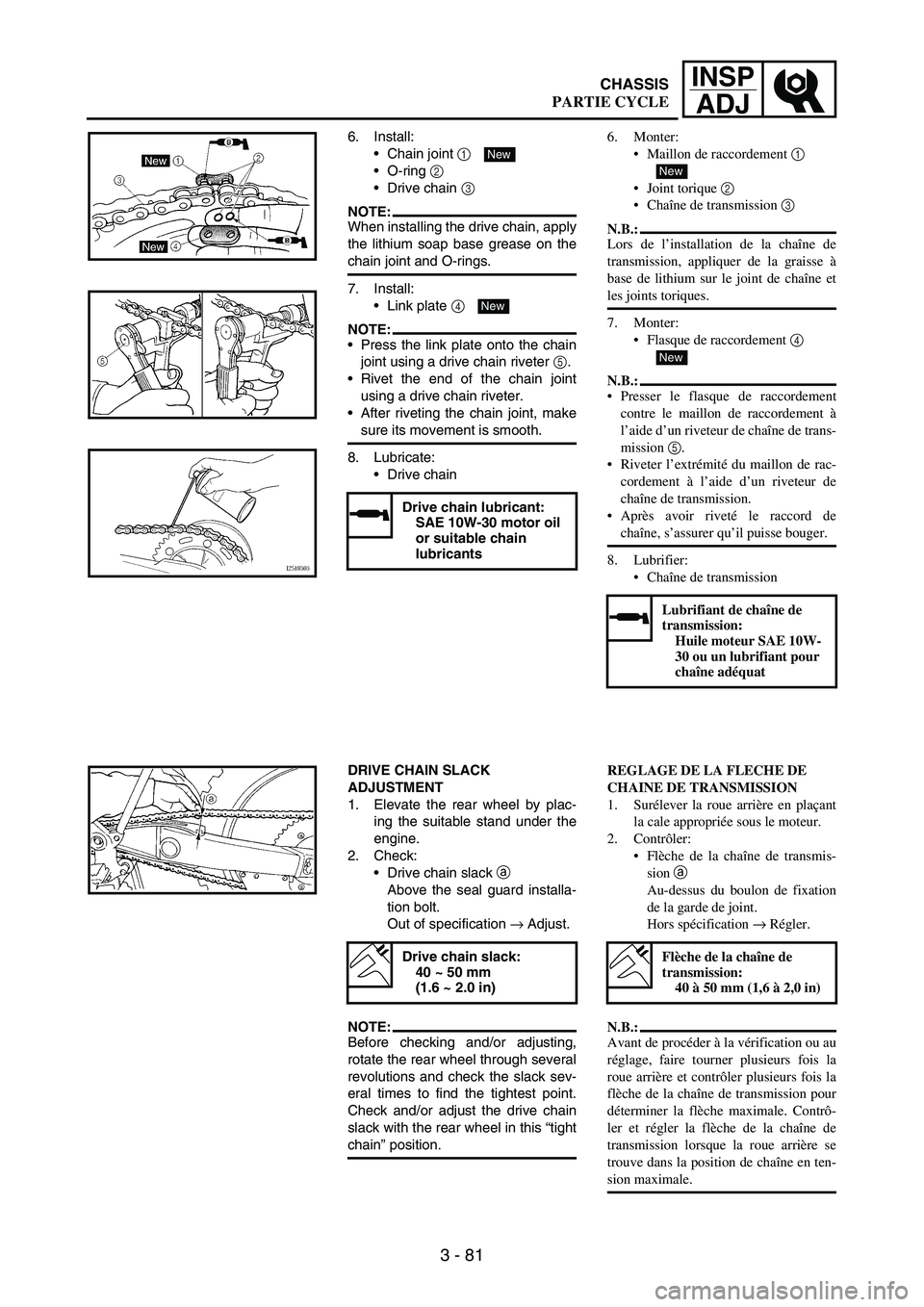
6. Install:
Chain joint
1
O-ring
2
Drive chain
3
NOTE:When installing the drive chain, apply
the lithium soap base grease on the
chain joint and O-rings.
7. Install:
Link plate
4
NOTE:Press the link plate onto the chain
joint using a drive chain riveter
5.
Rivet the end of the chain joint
using a drive chain riveter.
After riveting the chain joint, make
sure its movement is smooth.
8. Lubricate:
Drive chain
Drive chain lubricant:
SAE 10W-30 motor oil
or suitable chain
lubricants
New
New
DRIVE CHAIN SLACK
ADJUSTMENT
1. Elevate the rear wheel by plac-
ing the suitable stand under the
engine.
2. Check:
Drive chain slack
a
Above the seal guard installa-
tion bolt.
Out of specification
→ Adjust.
NOTE:Before checking and/or adjusting,
rotate the rear wheel through several
revolutions and check the slack sev-
eral times to find the tightest point.
Check and/or adjust the drive chain
slack with the rear wheel in this “tight
chain” position.
Drive chain slack:
40 ~ 50 mm
(1.6 ~ 2.0 in)
6. Monter:
Maillon de raccordement 1
Joint torique 2
Chaîne de transmission 3
N.B.:
Lors de l’installation de la chaîne de
transmission, appliquer de la graisse à
base de lithium sur le joint de chaîne et
les joints toriques.
7. Monter:
Flasque de raccordement 4
N.B.:
Presser le flasque de raccordement
contre le maillon de raccordement à
l’aide d’un riveteur de chaîne de trans-
mission 5.
Riveter l’extrémité du maillon de rac-
cordement à l’aide d’un riveteur de
chaîne de transmission.
Après avoir riveté le raccord de
chaîne, s’assurer qu’il puisse bouger.
8. Lubrifier:
Chaîne de transmission
Lubrifiant de chaîne de
transmission:
Huile moteur SAE 10W-
30 ou un lubrifiant pour
chaîne adéquat
New
New
REGLAGE DE LA FLECHE DE
CHAINE DE TRANSMISSION
1. Surélever la roue arrière en plaçant
la cale appropriée sous le moteur.
2. Contrôler:
Flèche de la chaîne de transmis-
sion a
Au-dessus du boulon de fixation
de la garde de joint.
Hors spécification → Régler.
N.B.:
Avant de procéder à la vérification ou au
réglage, faire tourner plusieurs fois la
roue arrière et contrôler plusieurs fois la
flèche de la chaîne de transmission pour
déterminer la flèche maximale. Contrô-
ler et régler la flèche de la chaîne de
transmission lorsque la roue arrière se
trouve dans la position de chaîne en ten-
sion maximale.
Flèche de la chaîne de
transmission:
40 à 50 mm (1,6 à 2,0 in)
CHASSIS
PARTIE CYCLE
Page 300 of 860

3 - 109
INSP
ADJ
2. Attach:
Timing light
Inductive tachometer
To the ignition coil lead
(orange lead
1).
Timing light:
YM-33277-A/
90890-03141
Inductive tachometer:
YU-8036-B
Engine tachometer:
90890-03113
1
3. Check:
Ignition timing
4. Install:
Timing mark accessing screw Checking steps:
Start the engine and let it warm
up. Let the engine run at the
specified speed.
Adjust the engine idling speed.
Refer to “ENGINE IDLING
SPEED ADJUSTMENT” sec-
tion.
Visually check the stationary
pointer
a is within the firing
range b on the rotor.
Incorrect firing range → Check
rotor and pickup assembly.
2. Attacher:
Lampe stroboscopique à induc-
tion
Compte-tours inductif
Au fil de la bobine d’allumage
(fil orange 1)
Lampe stroboscopique à
induction:
YM-33277-A/
90890-03141
Compte-tours inductif:
YU-8036-B
Compte-tours moteur:
90890-03113
3. Contrôler:
Avance à l’allumage
4. Monter:
Vis d’accès du repère de distribu-
tion Etapes de la vérification:
Mettre le moteur en marche et le
laisser chauffer. Laisser ensuite
tourner le moteur au régime spéci-
fié.
Régler la vitesse du ralenti du
moteur.
Se reporter à la section
“REGLAGE DU REGIME DE
RALENTI”.
S’assurer que l’index fixe a se
trouve dans la plage d’allumage b
sur le rotor.
Plage d’allumage incorrecte →
Contrôler le rotor et le circuit
d’excitation.
ELECTRICAL
PARTIE ELECTRIQUE
Page 318 of 860
3 - 127
INSP
ADJ
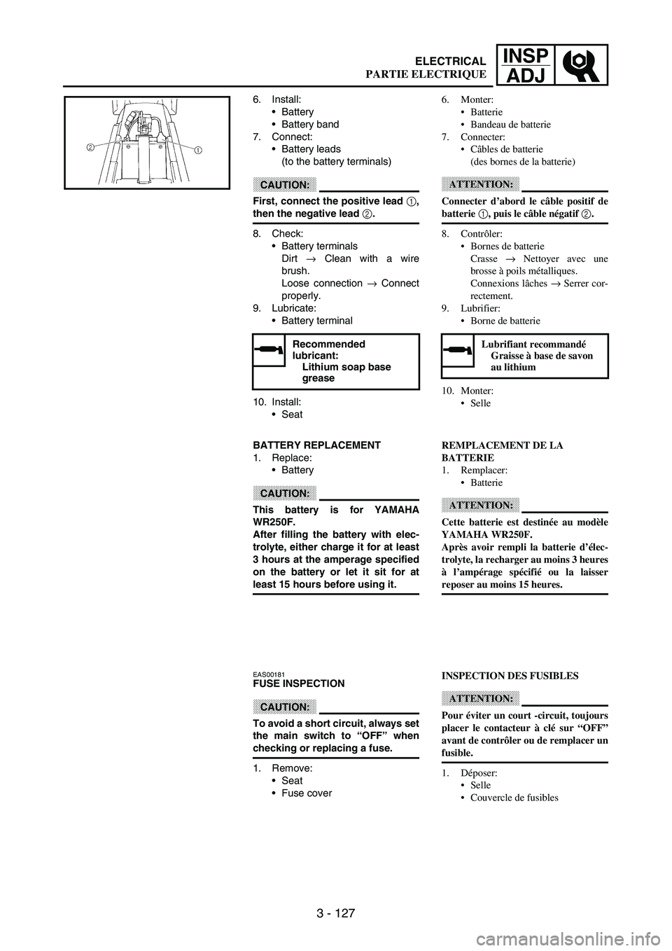
6. Install:
Battery
Battery band
7. Connect:
Battery leads
(to the battery terminals)
CAUTION:
First, connect the positive lead 1,
then the negative lead 2.
8. Check:
Battery terminals
Dirt
→ Clean with a wire
brush.
Loose connection
→ Connect
properly.
9. Lubricate:
Battery terminal
10. Install:
Seat
Recommended
lubricant:
Lithium soap base
grease
BATTERY REPLACEMENT
1. Replace:
Battery
CAUTION:
This battery is for YAMAHA
WR250F.
After filling the battery with elec-
trolyte, either charge it for at least
3 hours at the amperage specified
on the battery or let it sit for at
least 15 hours before using it.
EAS00181 FUSE INSPECTION
CAUTION:
To avoid a short circuit, always set
the main switch to “OFF” when
checking or replacing a fuse.
1. Remove:
Seat
Fuse cover6. Monter:
Batterie
Bandeau de batterie
7. Connecter:
Câbles de batterie
(des bornes de la batterie)
ATTENTION:
Connecter d’abord le câble positif de
batterie 1, puis le câble négatif 2.
8. Contrôler:
Bornes de batterie
Crasse → Nettoyer avec une
brosse à poils métalliques.
Connexions lâches → Serrer cor-
rectement.
9. Lubrifier:
Borne de batterie
10. Monter:
Selle
Lubrifiant recommandé
Graisse à base de savon
au lithium
REMPLACEMENT DE LA
BATTERIE
1. Remplacer:
Batterie
ATTENTION:
Cette batterie est destinée au modèle
YAMAHA WR250F.
Après avoir rempli la batterie d’élec-
trolyte, la recharger au moins 3 heures
à l’ampérage spécifié ou la laisser
reposer au moins 15 heures.
INSPECTION DES FUSIBLES
ATTENTION:
Pour éviter un court -circuit, toujours
placer le contacteur à clé sur “OFF”
avant de contrôler ou de remplacer un
fusible.
1. Déposer:
Selle
Couvercle de fusibles
ELECTRICAL
PARTIE ELECTRIQUE
Page 390 of 860

4 - 65
ENGCAMSHAFTS
Decompression system
1. Check:
Decompression system
Checking steps:
Check that the decompression
mechanism cam
1 moves
smoothly.
Check that the decompression
mechanism cam lever pin
2
projects from the camshaft.
Timing chain tensioner
1. Check:
While pressing the tensioner
rod lightly with fingers, use a
thin screwdriver
1 and wind
the tensioner rod up fully
clockwise.
When releasing the screw-
driver by pressing lightly with
fingers, make sure that the
tensioner rod will come out
smoothly.
If not, replace the tensioner
assembly.
ASSEMBLY AND INSTALLATION
Camshaft
1. Install:
Exhaust camshaft
1
Intake camshaft
2
Installation steps:
Turn the crankshaft counter-
clockwise with a wrench.
NOTE:Apply the molybdenum disulfide
oil on the camshafts.
Apply the engine oil on the
decompression system.
Squeezing the decompression
lever allows the crankshaft to
be turned easily.
Align the T.D.C. mark
a on the
rotor with the align mark
b on
the crankcase cover when pis-
ton is at T.D.C. on compression
stroke.
Système de décompression
1. Contrôler:
Système de décompression
Points à contrôler:
S’assurer que la came de décom-
presseur 1 tourne en douceur.
S’assurer que la goupille du levier
de la came de décompresseur 2
ressorte de l’arbre à cames.
Tendeur de la chaîne de distribution
1. Contrôler:
Tout en comprimant légèrement
la tige du tendeur à l’aide du
doigt, la visser complètement
(tourner dans le sens des aiguilles
d’une montre) en se servant d’un
tournevis fin 1.
Après avoir retiré le tournevis en
appuyant légèrement du doigt,
vérifier si la tige du tendeur sort
sans problème.
Si elle ne sort pas, remplacer le
tendeur.
ASSEMBLAGE ET MONTAGE
Arbre à cames
1. Monter:
Arbre à cames d’échappement 1
Arbre à cames d’admission 2
Etapes de montage:
Tourner le vilebrequin à l’aide
d’une clé dans le sens inverse des
aiguilles d’une montre.
N.B.:
Appliquer de l’huile au bisulfure
de molybdène sur les arbres à
cames.
Appliquer de l’huile moteur sur le
système de décompression.
Actionner le levier de décompres-
sion a fin de faciliter la rotation du
rilebrequin.
Aligner le repère de PMH a sur le
rotor le repère d’alignement b sur
le couvercle du carter quand le pis-
ton se trouve au Point Mort Haut
(PMH) sur la courge de compres-
sion.
ARBRES A CAMES
Page 660 of 860
5 - 83
CHASFRONT FORK
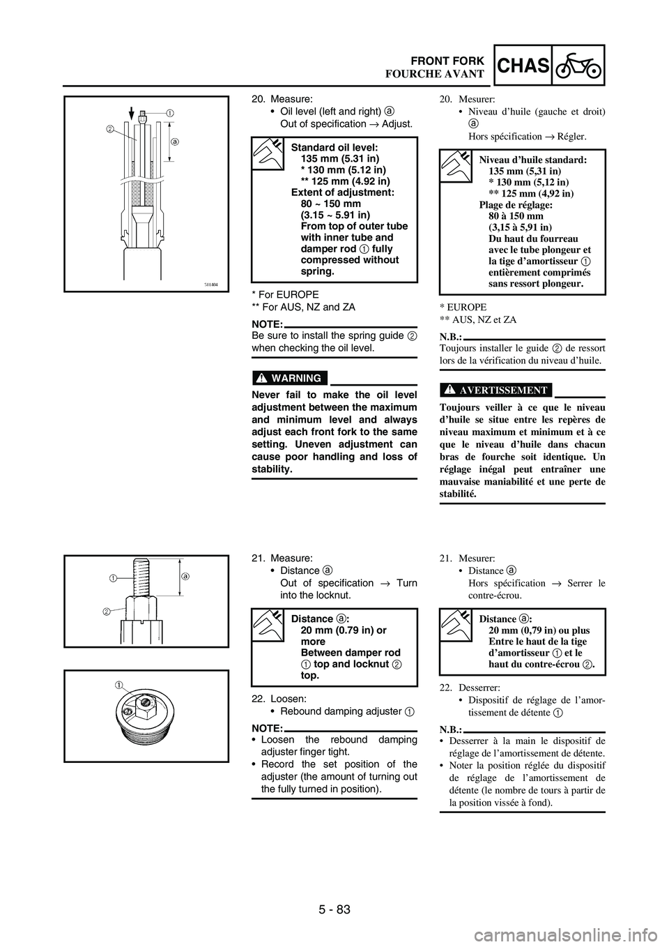
20. Measure:
Oil level (left and right)
a
Out of specification
→ Adjust.
* For EUROPE
** For AUS, NZ and ZA
NOTE:Be sure to install the spring guide
2
when checking the oil level.
WARNING
Never fail to make the oil level
adjustment between the maximum
and minimum level and always
adjust each front fork to the same
setting. Uneven adjustment can
cause poor handling and loss of
stability.
Standard oil level:
135 mm (5.31 in)
* 130 mm (5.12 in)
** 125 mm (4.92 in)
Extent of adjustment:
80 ~ 150 mm
(3.15 ~ 5.91 in)
From top of outer tube
with inner tube and
damper rod 1
fully
compressed without
spring.
21. Measure:
Distance
a
Out of specification
→ Turn
into the locknut.
22. Loosen:
Rebound damping adjuster
1
NOTE:Loosen the rebound damping
adjuster finger tight.
Record the set position of the
adjuster (the amount of turning out
the fully turned in position).
Distance a
:
20 mm (0.79 in) or
more
Between damper rod
1
top and locknut 2
top.
20. Mesurer:
Niveau d’huile (gauche et droit)
a
Hors spécification → Régler.
* EUROPE
** AUS, NZ et ZA
N.B.:
Toujours installer le guide 2 de ressort
lors de la vérification du niveau d’huile.
AVERTISSEMENT
Toujours veiller à ce que le niveau
d’huile se situe entre les repères de
niveau maximum et minimum et à ce
que le niveau d’huile dans chacun
bras de fourche soit identique. Un
réglage inégal peut entraîner une
mauvaise maniabilité et une perte de
stabilité.
Niveau d’huile standard:
135 mm (5,31 in)
* 130 mm (5,12 in)
** 125 mm (4,92 in)
Plage de réglage:
80 à 150 mm
(3,15 à 5,91 in)
Du haut du fourreau
avec le tube plongeur et
la tige d’amortisseur 1
entièrement comprimés
sans ressort plongeur.
21. Mesurer:
Distance a
Hors spécification → Serrer le
contre-écrou.
22. Desserrer:
Dispositif de réglage de l’amor-
tissement de détente 1
N.B.:
Desserrer à la main le dispositif de
réglage de l’amortissement de détente.
Noter la position réglée du dispositif
de réglage de l’amortissement de
détente (le nombre de tours à partir de
la position vissée à fond).
Distance a:
20 mm (0,79 in) ou plus
Entre le haut de la tige
d’amortisseur 1 et le
haut du contre-écrou 2.
FOURCHE AVANT
Page 741 of 860
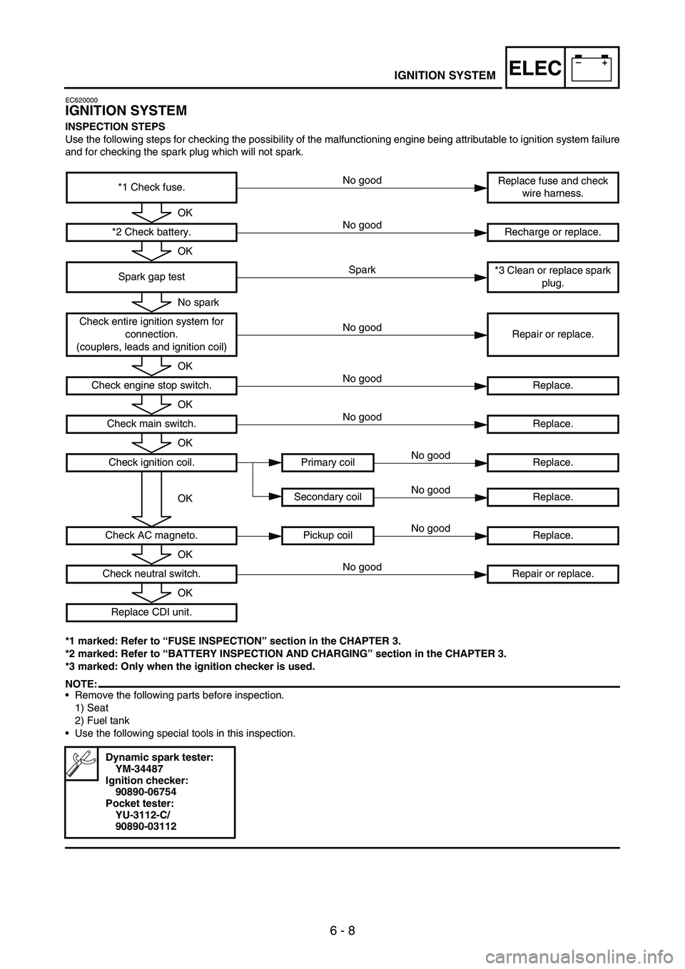
6 - 8
–+ELECIGNITION SYSTEM
EC620000
IGNITION SYSTEM
INSPECTION STEPS
Use the following steps for checking the possibility of the malfunctioning engine being attributable to ignition system failure
and for checking the spark plug which will not spark.
*1 marked: Refer to “FUSE INSPECTION” section in the CHAPTER 3.
*2 marked: Refer to “BATTERY INSPECTION AND CHARGING” section in the CHAPTER 3.
*3 marked: Only when the ignition checker is used.
NOTE:Remove the following parts before inspection.
1) Seat
2) Fuel tank
Use the following special tools in this inspection.
*1 Check fuse.Replace fuse and check
wire harness.
*2 Check battery. Recharge or replace.
Spark gap test*3 Clean or replace spark
plug.
Check entire ignition system for
connection.
(couplers, leads and ignition coil)Repair or replace.
Check engine stop switch. Replace.
Check main switch.Replace.
Check ignition coil. Primary coil Replace.
Secondary coil Replace.
Check AC magneto. Pickup coil Replace.
Check neutral switch. Repair or replace.
Replace CDI unit.
Dynamic spark tester:
YM-34487
Ignition checker:
90890-06754
Pocket tester:
YU-3112-C/
90890-03112
No good
OK
No good
OK
Spark
No spark
No good
OK
No good
OK
No good
OK
No good
OKNo good
No good
OK
No good
OK
Page 784 of 860
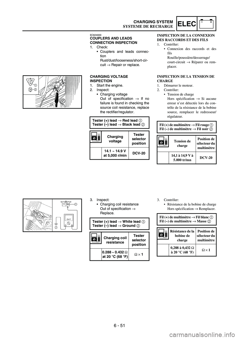
6 - 51
–+ELECCHARGING SYSTEM
EC624000COUPLERS AND LEADS
CONNECTION INSPECTION
1. Check:
Couplers and leads connec-
tion
Rust/dust/looseness/short-cir-
cuit
→ Repair or replace.
CHARGING VOLTAGE
INSPECTION
1. Start the engine.
2. Inspect:
Charging voltage
Out of specification
→ If no
failure is found in checking the
source coil resistance, replace
the rectifier/regulator.
Tester (+) lead →
Red lead 1
Tester (–) lead →
Black lead 2
Charging
voltageTester
selector
position
14.1 ~ 14.9 V
at 5,000 r/minDCV-20
R
BW Y1
2
3. Inspect:
Charging coil resistance
Out of specification
→
Replace.
Tester (+) lead →
White lead 1
Tester (–) lead →
Ground 2
Charging coil
resistanceTester
selector
position
0.288 ~ 0.432 Ω
at 20 °C (68 °F)Ω
×
1
INSPECTION DE LA CONNEXION
DES RACCORDS ET DES FILS
1. Contrôler:
Connexion des raccords et des
fils
Rouille/poussière/desserrage/
court-circuit → Réparer ou rem-
placer.
INSPECTION DE LA TENSION DE
CHARGE
1. Démarrer le moteur.
2. Contrôler:
Tension de charge
Hors spécification → Si aucune
erreur n’est détectée lors du con-
trôle de la résistance de la bobine
source, remplacer le redresseur/
régulateur.
Fil (+) de multimètre → Fil rouge 1
Fil (–) de multimètre → Fil noir 2
Tension de
chargePosition de
sélecteur du
multimètre
14,1 à 14,9 V à
5.000 tr/mnDCV-20
3. Contrôler:
Résistance de la bobine de charge
Hors spécification → Remplacer.
Fil (+) de multimètre → Fil blanc 1
Fil (–) de multimètre → Masse 2
Résistance de la
bobine de
chargePosition de
sélecteur du
multimètre
0,288 à 0,432 Ω
à 20 °C (68 °F)Ω × 1
SYSTEME DE RECHARGE