torque YAMAHA WR 250F 2003 Manuale de Empleo (in Spanish)
[x] Cancel search | Manufacturer: YAMAHA, Model Year: 2003, Model line: WR 250F, Model: YAMAHA WR 250F 2003Pages: 860, tamaño PDF: 35.16 MB
Page 292 of 860

3 - 101
INSP
ADJ
2. Inspect:
Bearing free play
Exist play
→ Replace.
EC36U013STEERING HEAD INSPECTION
AND ADJUSTMENT
1. Elevate the front wheel by plac-
ing a suitable stand under the
engine.
2. Check:
Steering stem
Grasp the bottom of the forks
and gently rock the fork
assembly back and forth.
Free play
→ Adjust steering
head.
3. Check:
Steering smooth action
Turn the handlebar lock to
lock.
Unsmooth action
→ Adjust
steering ring nut.
4. Adjust:
Steering ring nut
Steering ring nut adjustment
steps:
Remove the headlight.
Remove the handlebar and
handlebar upper bracket.
Loosen the steering ring nut
1
using the steering nut wrench
2.
Steering nut wrench:
YU-33975/90890-01403
Tighten the steering ring nut
3
using steering nut wrench
4.
NOTE:Set the torque wrench to the
steering nut wrench so that they
form a right angle.
Steering nut wrench:
YU-33975/90890-01403
T R..
Steering ring nut
(initial tightening):
38 Nm
(3.8 m kg, 27 ft lb)
2. Contrôler:
Jeu de roulement
Il y a du jeu → Remplacer.
CONTROLE ET REGLAGE DE LA
TETE DE FOURCHE
1. Soulever la roue avant en mettant
un support convenable sous le
moteur.
2. Contrôler:
Arbre de direction
Saisir la fourche par le bas et bas-
culer l’ensemble en avant et en
arrière.
Jeu → Régler la tête de fourche.
3. Contrôler:
Action régulière de la direction
Tourner le guidon à fond dans les
deux sens.
Action irrégulière → Régler
l’écrou annulaire de direction.
4. Régler:
Ecrou crénelé de direction
Etapes de réglage de l’écrou cré-
nelé de direction:
Retirer le phare.
Retirer le guidon et le support
supérieur.
Desserrer l’écrou crénelé de direc-
tion 1 en utilisant la clé à ergots
2.
Clé à ergots:
YU-33975/90890-01403
Serrer l’écrou crénelé de direction
3 en utilisant la clé 4.
N.B.:
Régler la clef dynamométrique à la
clé à ergots pour former un angle
droit.
Clé à ergots:
YU-33975/90890-01403
T R..
Ecrou crénelé de direction
(serrage initial):
38 Nm
(3,8 m kg, 27 ft lb)
CHASSIS
PARTIE CYCLE
Page 394 of 860
4 - 69
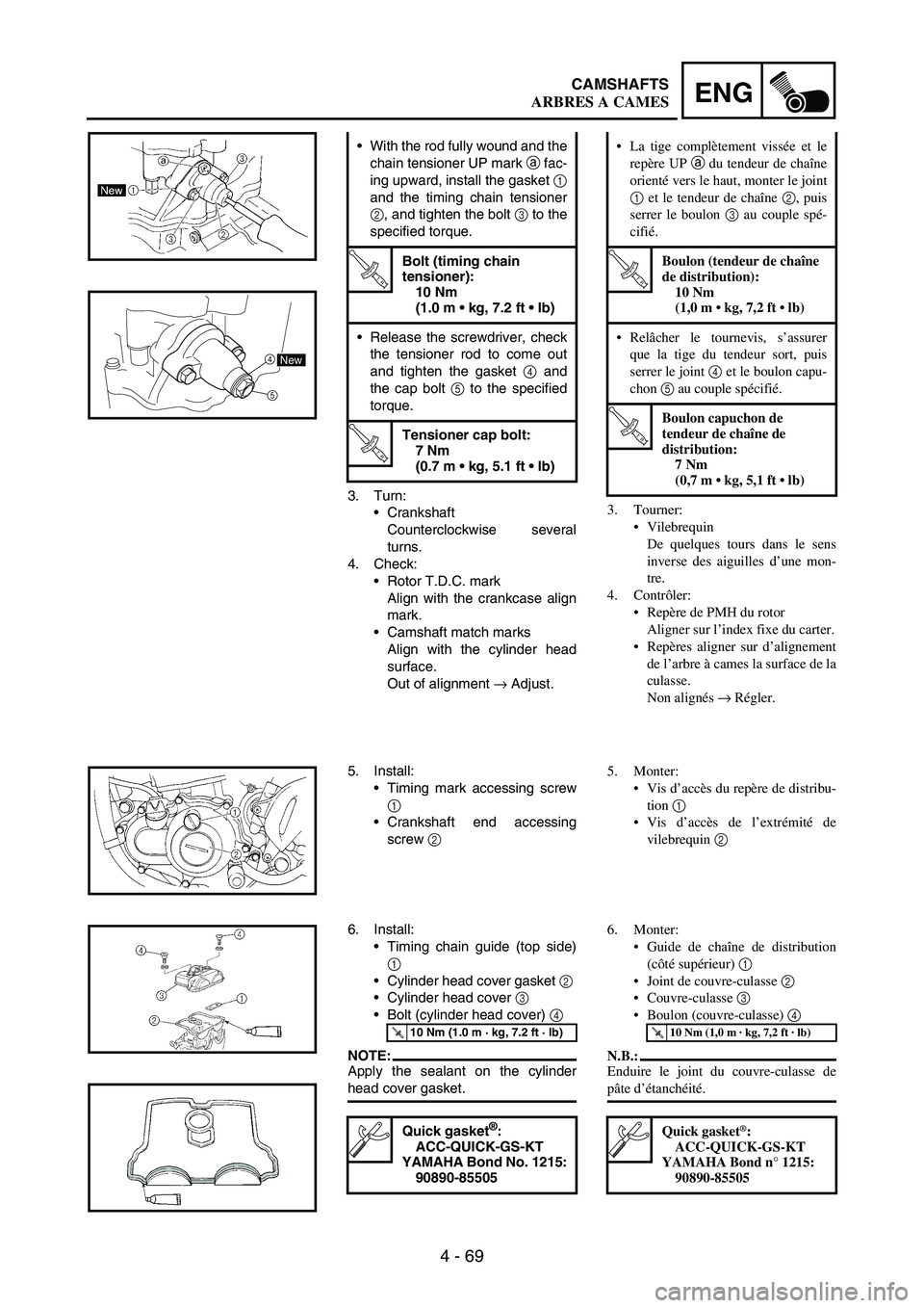
ENGCAMSHAFTS
3. Turn:
Crankshaft
Counterclockwise several
turns.
4. Check:
Rotor T.D.C. mark
Align with the crankcase align
mark.
Camshaft match marks
Align with the cylinder head
surface.
Out of alignment
→ Adjust. With the rod fully wound and the
chain tensioner UP mark
a fac-
ing upward, install the gasket
1
and the timing chain tensioner
2, and tighten the bolt
3 to the
specified torque.
T R..
Bolt (timing chain
tensioner):
10 Nm
(1.0 m kg, 7.2 ft lb)
Release the screwdriver, check
the tensioner rod to come out
and tighten the gasket
4 and
the cap bolt
5 to the specified
torque.
T R..
Tensioner cap bolt:
7 Nm
(0.7 m kg, 5.1 ft lb)
5
4New
5. Install:
Timing mark accessing screw
1
Crankshaft end accessing
screw
2
6. Install:
Timing chain guide (top side)
1
Cylinder head cover gasket
2
Cylinder head cover
3
Bolt (cylinder head cover)
4
NOTE:Apply the sealant on the cylinder
head cover gasket.
T R..10 Nm (1.0 m · kg, 7.2 ft · lb)
Quick gasket®:
ACC-QUICK-GS-KT
YAMAHA Bond No. 1215:
90890-85505
3. Tourner:
Vilebrequin
De quelques tours dans le sens
inverse des aiguilles d’une mon-
tre.
4. Contrôler:
Repère de PMH du rotor
Aligner sur l’index fixe du carter.
Repères aligner sur d’alignement
de l’arbre à cames la surface de la
culasse.
Non alignés → Régler. La tige complètement vissée et le
repère UP a du tendeur de chaîne
orienté vers le haut, monter le joint
1 et le tendeur de chaîne 2, puis
serrer le boulon 3 au couple spé-
cifié.
T R..
Boulon (tendeur de chaîne
de distribution):
10 Nm
(1,0 m kg, 7,2 ft lb)
Relâcher le tournevis, s’assurer
que la tige du tendeur sort, puis
serrer le joint 4
et le boulon capu-
chon 5 au couple spécifié.
T R..
Boulon capuchon de
tendeur de chaîne de
distribution:
7 Nm
(0,7 m kg, 5,1 ft lb)
5. Monter:
Vis d’accès du repère de distribu-
tion 1
Vis d’accès de l’extrémité de
vilebrequin 2
6. Monter:
Guide de chaîne de distribution
(côté supérieur) 1
Joint de couvre-culasse 2
Couvre-culasse 3
Boulon (couvre-culasse) 4
N.B.:
Enduire le joint du couvre-culasse de
pâte d’étanchéité.
T R..10 Nm (1,0 m · kg, 7,2 ft · lb)
Quick gasket®:
ACC-QUICK-GS-KT
YAMAHA Bond n° 1215:
90890-85505
ARBRES A CAMES
Page 540 of 860
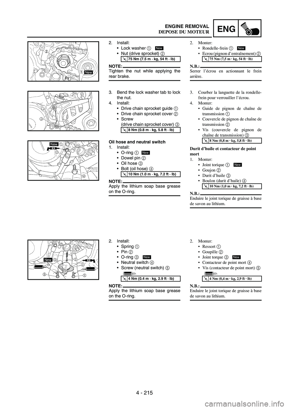
4 - 215
ENGENGINE REMOVAL
2. Install:
Lock washer
1
Nut (drive sprocket)
2
NOTE:Tighten the nut while applying the
rear brake.
T R..75 Nm (7.5 m · kg, 54 ft · lb)
New
3. Bend the lock washer tab to lock
the nut.
4. Install:
Drive chain sprocket guide
1
Drive chain sprocket cover
2
Screw
(drive chain sprocket cover)
3
T R..8 Nm (0.8 m · kg, 5.8 ft · lb)
Oil hose and neutral switch
1. Install:
O-ring
1
Dowel pin
2
Oil hose
3
Bolt (oil hose)
4
NOTE:Apply the lithium soap base grease
on the O-ring.
T R..10 Nm (1.0 m · kg, 7.2 ft · lb)
New
2. Install:
Spring
1
Pin
2
O-ring
3
Neutral switch
4
Screw (neutral switch)
5
NOTE:Apply the lithium soap base grease
on the O-ring.
T R..4 Nm (0.4 m · kg, 2.9 ft · lb)
New
2. Monter:
Rondelle-frein 1
Ecrou (pignon d’entraînement) 2
N.B.:
Serrer l’écrou en actionnant le frein
arrière.
T R..75 Nm (7,5 m · kg, 54 ft · lb)
New
3. Courber la languette de la rondelle-
frein pour verrouiller l’écrou.
4. Monter:
Guide de pignon de chaîne de
transmission 1
Couvercle de pignon de chaîne de
transmission 2
Vis (couvercle de pignon de
chaîne de transmission) 3
Durit d’huile et contacteur de point
mort
1. Monter:
Joint torique 1
Goujon 2
Durit d’huile 3
Boulon (durit d’huile) 4
N.B.:
Enduire le joint torique de graisse à base
de savon au lithium.
T R..8 Nm (0,8 m · kg, 5,8 ft · lb)
T R..10 Nm (1,0 m · kg, 7,2 ft · lb)
New
2. Monter:
Ressort 1
Goupille 2
Joint torque 3
Contacteur de point mort 4
Vis (contacteur de point mort) 5
N.B.:
Enduire le joint torique de graisse à base
de savon au lithium.
T R..4 Nm (0,4 m · kg, 2,9 ft · lb)
New
DEPOSE DU MOTEUR
Page 662 of 860
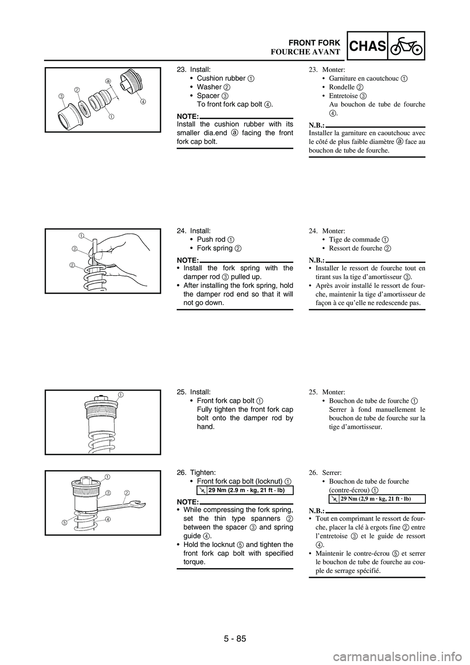
5 - 85
CHASFRONT FORK
23. Install:
Cushion rubber
1
Washer
2
Spacer
3
To front fork cap bolt
4.
NOTE:Install the cushion rubber with its
smaller dia.end
a facing the front
fork cap bolt.
24. Install:
Push rod
1
Fork spring
2
NOTE:Install the fork spring with the
damper rod
3 pulled up.
After installing the fork spring, hold
the damper rod end so that it will
not go down.
25. Install:
Front fork cap bolt
1
Fully tighten the front fork cap
bolt onto the damper rod by
hand.
26. Tighten:
Front fork cap bolt (locknut)
1
NOTE:While compressing the fork spring,
set the thin type spanners
2
between the spacer
3 and spring
guide
4.
Hold the locknut
5 and tighten the
front fork cap bolt with specified
torque.
T R..29 Nm (2.9 m · kg, 21 ft · lb)
23. Monter:
Garniture en caoutchouc 1
Rondelle 2
Entretoise 3
Au bouchon de tube de fourche
4.
N.B.:
Installer la garniture en caoutchouc avec
le côté de plus faible diamètre a face au
bouchon de tube de fourche.
24. Monter:
Tige de commade 1
Ressort de fourche 2
N.B.:
Installer le ressort de fourche tout en
tirant sus la tige d’amortisseur 3.
Après avoir installé le ressort de four-
che, maintenir la tige d’amortisseur de
façon à ce qu’elle ne redescende pas.
25. Monter:
Bouchon de tube de fourche 1
Serrer à fond manuellement le
bouchon de tube de fourche sur la
tige d’amortisseur.
26. Serrer:
Bouchon de tube de fourche
(contre-écrou) 1
N.B.:
Tout en comprimant le ressort de four-
che, placer la clé à ergots fine 2 entre
l’entretoise 3 et le guide de ressort
4.
Maintenir le contre-écrou 5 et serrer
le bouchon de tube de fourche au cou-
ple de serrage spécifié.
T R..29 Nm (2,9 m · kg, 21 ft · lb)
FOURCHE AVANT
Page 664 of 860
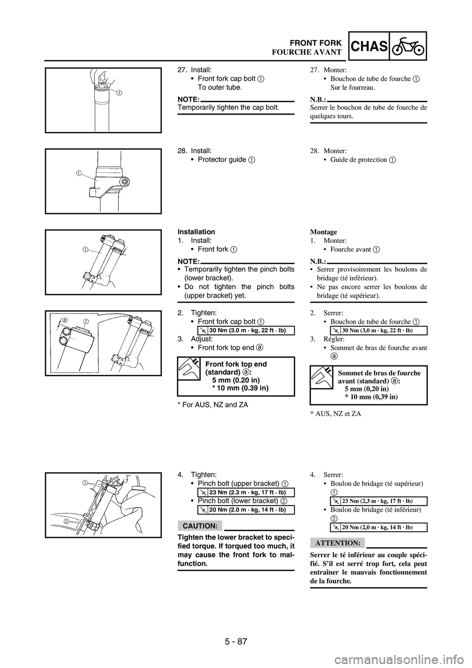
5 - 87
CHASFRONT FORK
27. Install:
Front fork cap bolt
1
To outer tube.
NOTE:Temporarily tighten the cap bolt.
28. Install:
Protector guide
1
Installation
1. Install:
Front fork
1
NOTE:Temporarily tighten the pinch bolts
(lower bracket).
Do not tighten the pinch bolts
(upper bracket) yet.
2. Tighten:
Front fork cap bolt
1
3. Adjust:
Front fork top end
a
* For AUS, NZ and ZA
T R..30 Nm (3.0 m · kg, 22 ft · lb)
Front fork top end
(standard) a
:
5 mm (0.20 in)
* 10 mm (0.39 in)
4. Tighten:
Pinch bolt (upper bracket)
1
Pinch bolt (lower bracket)
2
CAUTION:
Tighten the lower bracket to speci-
fied torque. If torqued too much, it
may cause the front fork to mal-
function.
T R..23 Nm (2.3 m · kg, 17 ft · lb)
T R..20 Nm (2.0 m · kg, 14 ft · lb)
27. Monter:
Bouchon de tube de fourche 1
Sur le fourreau.
N.B.:
Serrer le bouchon de tube de fourche de
quelques tours.
28. Monter:
Guide de protection 1
Montage
1. Monter:
Fourche avant 1
N.B.:
Serrer provisoirement les boulons de
bridage (té inférieur).
Ne pas encore serrer les boulons de
bridage (té supérieur).
2. Serrer:
Bouchon de tube de fourche 1
3. Régler:
Sommet de bras de fourche avant
a
* AUS, NZ et ZA
T R..30 Nm (3,0 m · kg, 22 ft · lb)
Sommet de bras de fourche
avant (standard) a:
5 mm (0,20 in)
* 10 mm (0,39 in)
4. Serrer:
Boulon de bridage (té supérieur)
1
Boulon de bridage (té inférieur)
2
ATTENTION:
Serrer le té inférieur au couple spéci-
fié. S’il est serré trop fort, cela peut
entraîner le mauvais fonctionnement
de la fourche.
T R..23 Nm (2,3 m · kg, 17 ft · lb)
T R..20 Nm (2,0 m · kg, 14 ft · lb)
FOURCHE AVANT
Page 694 of 860
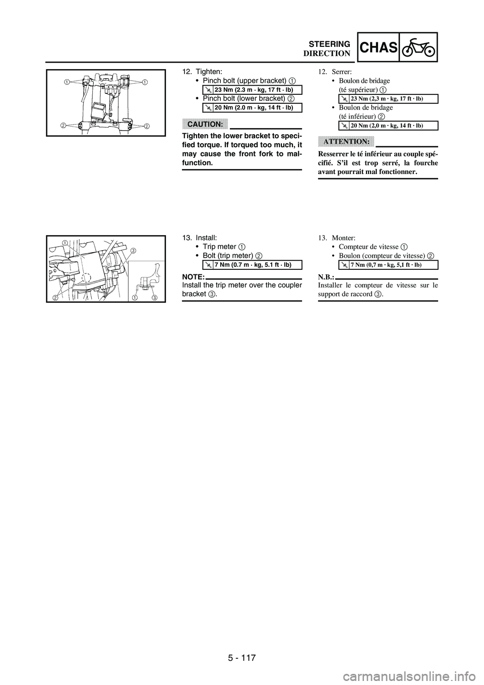
5 - 117
CHASSTEERING
12. Tighten:
Pinch bolt (upper bracket)
1
Pinch bolt (lower bracket)
2
CAUTION:
Tighten the lower bracket to speci-
fied torque. If torqued too much, it
may cause the front fork to mal-
function.
T R..23 Nm (2.3 m · kg, 17 ft · lb)
T R..20 Nm (2.0 m · kg, 14 ft · lb)
13. Install:
Trip meter
1
Bolt (trip meter)
2
NOTE:Install the trip meter over the coupler
bracket
3.
T R..7 Nm (0.7 m · kg, 5.1 ft · lb)
12. Serrer:
Boulon de bridage
(té supérieur) 1
Boulon de bridage
(té inférieur) 2
ATTENTION:
Resserrer le té inférieur au couple spé-
cifié. S’il est trop serré, la fourche
avant pourrait mal fonctionner.
T R..23 Nm (2,3 m · kg, 17 ft · lb)
T R..20 Nm (2,0 m · kg, 14 ft · lb)
13. Monter:
Compteur de vitesse 1
Boulon (compteur de vitesse) 2
N.B.:
Installer le compteur de vitesse sur le
support de raccord 3.
T R..7 Nm (0,7 m · kg, 5,1 ft · lb)
DIRECTION
Page 848 of 860

7 - 41
TUNSETTING
EC72H002Suspension setting
Front fork
NOTE:If any of the following symptoms is experienced with the standard position as the base, make resetting by reference to
the adjustment procedure given in the same chart.
Before any change, set the rear shock absorber sunken length to the standard figure 90 ~ 100 mm (3.5 ~ 3.9 in).
SymptomSection
Check Adjust
JumpLarge
gapMedium
gapSmall
gap
Stiff over entire rangeCompression damping
Oil level (oil amount)
SpringTurn adjuster counterclockwise (about 2 clicks) to
decrease damping.
Decrease oil level by about 5 ~ 10 mm (0.2 ~ 0.4 in).
Replace with soft spring.
Unsmooth movement
over entire rangeOuter tube
Inner tube
Under bracket tightening
torqueCheck for any bends, dents, and other noticeable
scars, etc. If any, replace affected parts.
Retighten to specified torque.
Poor initial
movementRebound damping
Oil sealTurn adjuster counterclockwise (about 2 clicks) to
decrease damping.
Apply grease in oil seal wall.
Soft over entire
range, bottoming outCompression damping
Oil level (oil amount)
SpringTurn adjuster clockwise (about 2 clicks) to increase
damping.
Increase oil level by about 5 ~ 10 mm (0.2 ~ 0.4 in).
Replace with stiff spring.
Stiff toward stroke
endOil level (oil amount) Decrease oil level by about 5 mm (0.2 in).
Soft toward stroke
end, bottoming outOil level (oil amount) Increase oil level by about 5 mm (0.2 in).
Stiff initial movement Compression dampingTurn adjuster counterclockwise (about 2 clicks) to
decrease damping.
Low front, tending to
lower front postureCompression damping
Rebound damping
Balance with rear end
Oil level (oil amount)Turn adjuster clockwise (about 2 clicks) to increase
damping.
Turn adjuster counterclockwise (about 2 clicks) to
decrease damping.
Set sunken length for 95 ~ 100 mm (3.7 ~ 3.9 in)
when one passenger is astride seat (lower rear
posture).
Increase oil level by about 5 mm (0.2 in).
“Obtrusive” front,
tending to upper front
postureCompression damping
Balance with rear end
Spring
Oil lever (oil amount)Turn adjuster counterclockwise (about 2 clicks) to
decrease damping.
Set sunken length for 90 ~ 95 mm (3.5 ~ 3.7 in)
when one passenger is astride seat (upper rear
posture).
Replace with soft spring.
Decrease oil level by about 5 ~ 10 mm (0.2 ~ 0.4 in).