chain slack YAMAHA WR 250F 2003 Owners Manual
[x] Cancel search | Manufacturer: YAMAHA, Model Year: 2003, Model line: WR 250F, Model: YAMAHA WR 250F 2003Pages: 860, PDF Size: 35.16 MB
Page 92 of 860

MAINTENANCE SPECIFICATIONS
2 - 13
SPEC
Wheel: USA, CDN, ZA EUROPE, AUS, NZ
Front wheel type Spoke wheel←----
Rear wheel type Spoke wheel←----
Front rim size/material 21 × 1.60/Aluminum←----
Rear rim size/material 18 × 1.85/Aluminum 18 × 2.15/Aluminum ----
Rim runout limit:
Radial ---- ---- 2.0 mm
(0.08 in)
Lateral ---- ---- 2.0 mm
(0.08 in)
Drive chain:
Type/manufacturer DID520VM/DAIDO ----
Number of links 113 links + joint ----
Chain slack 40 ~ 50 mm (1.6 ~ 2.0 in) ----
Chain length (10 links) ---- 150.1 mm
(5.91 in)
Front disc brake:
Disc outside dia. × Thickness 250 × 3.0 mm (9.84 × 0.12 in)
250 × 2.5 mm
(9.84
× 0.10 in)
Pad thickness 4.4 mm (0.17 in) 1.0 mm
(0.04 in)
Master cylinder inside dia. 11.0 mm (0.433 in) ----
Caliper cylinder inside dia. 27.0 mm (1.063 in) × 2 ----
Brake fluid type DOT #4 ----
Rear disc brake:
Disc outside dia. × Thickness 245 × 4.0 mm (9.65 × 0.16 in)
245 × 3.5 mm
(9.65
× 0.14 in)
Deflection limit ---- 0.15 mm
(0.006 in)
Pad thickness 6.4 mm (0.25 in) 1.0 mm
(0.04 in)
Master cylinder inside dia. 11.0 mm (0.433 in) ----
Caliper cylinder inside dia. 25.4 mm (1.000 in) × 1 ----
Brake fluid type DOT #4 ----
Brake lever and brake pedal:
Brake lever position 95 mm (3.74 in) ----
Brake pedal height
(vertical height above footrest top)5 mm (0.20 in) ----
Clutch lever free play (lever end) 8 ~ 13 mm (0.31 ~ 0.51 in) ----
Throttle grip free play 3 ~ 5 mm (0.12 ~ 0.20 in) ----Item Standard Limit
Page 193 of 860
3 - 2
INSP
ADJ
MAINTENANCE INTERVALS
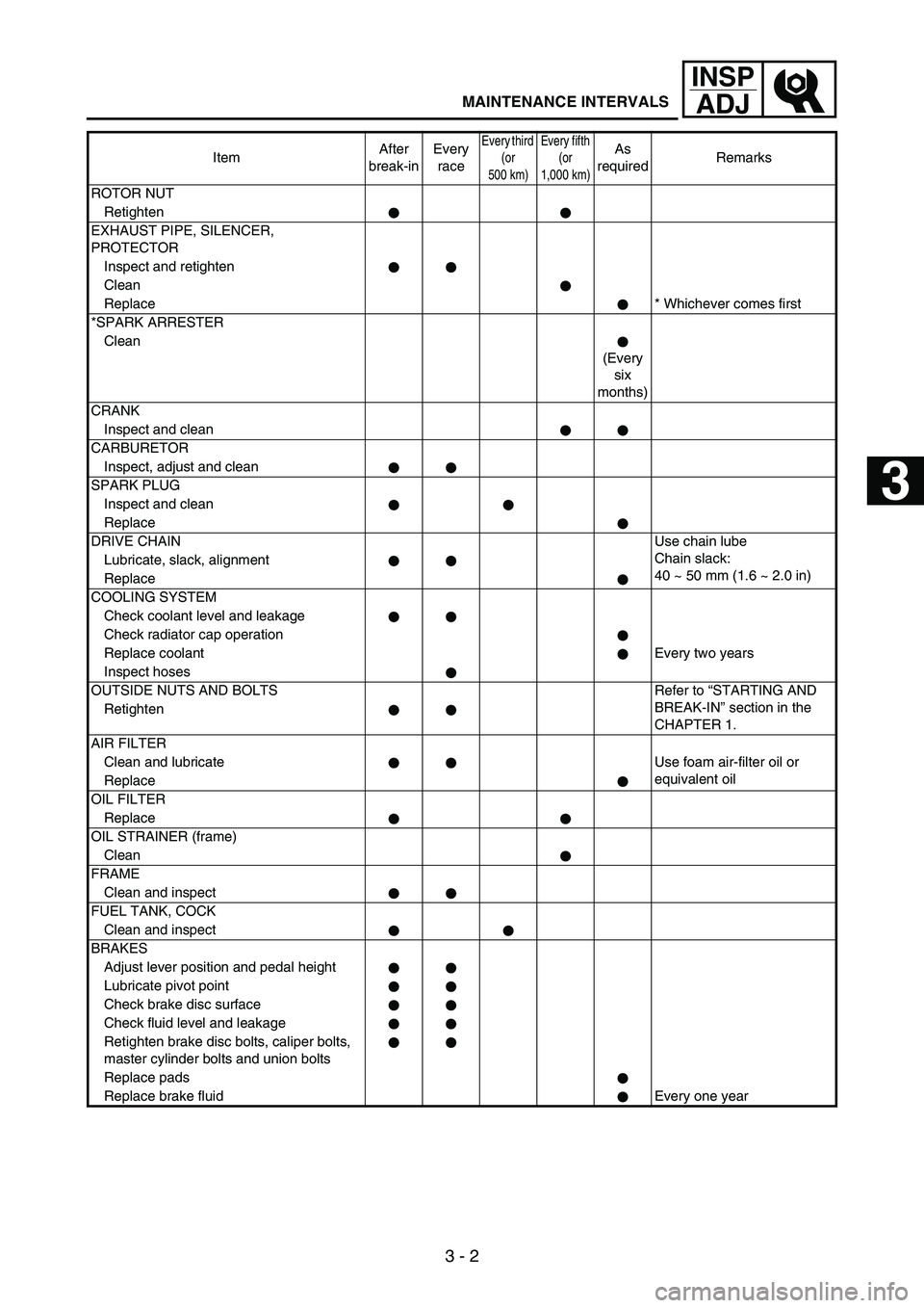
ROTOR NUT
Retighten
EXHAUST PIPE, SILENCER,
PROTECTOR
Inspect and retighten
Clean
Replace* Whichever comes first
*SPARK ARRESTER
Clean
(Every
six
months)
CRANK
Inspect and clean
CARBURETOR
Inspect, adjust and clean
SPARK PLUG
Inspect and clean
Replace
DRIVE CHAINUse chain lube
Chain slack:
40 ~ 50 mm (1.6 ~ 2.0 in) Lubricate, slack, alignment
Replace
COOLING SYSTEM
Check coolant level and leakage
Check radiator cap operation
Replace coolantEvery two years
Inspect hoses
OUTSIDE NUTS AND BOLTS Refer to “STARTING AND
BREAK-IN” section in the
CHAPTER 1. Retighten
AIR FILTER
Clean and lubricate Use foam air-filter oil or
equivalent oil
Replace
OIL FILTER
Replace
OIL STRAINER (frame)
Clean
FRAME
Clean and inspect
FUEL TANK, COCK
Clean and inspect
BRAKES
Adjust lever position and pedal height
Lubricate pivot point
Check brake disc surface
Check fluid level and leakage
Retighten brake disc bolts, caliper bolts,
master cylinder bolts and union bolts
Replace pads
Replace brake fluid Every one yearItemAfter
break-inEvery
race
Every third
(or
500 km)Every fifth
(or
1,000 km)As
requiredRemarks
1
2
3
4
5
6
7
Page 207 of 860
3 - 16
INSP
ADJ
PRE-OPERATION INSPECTION AND MAINTENANCE
EC320000
PRE-OPERATION INSPECTION AND MAINTENANCE
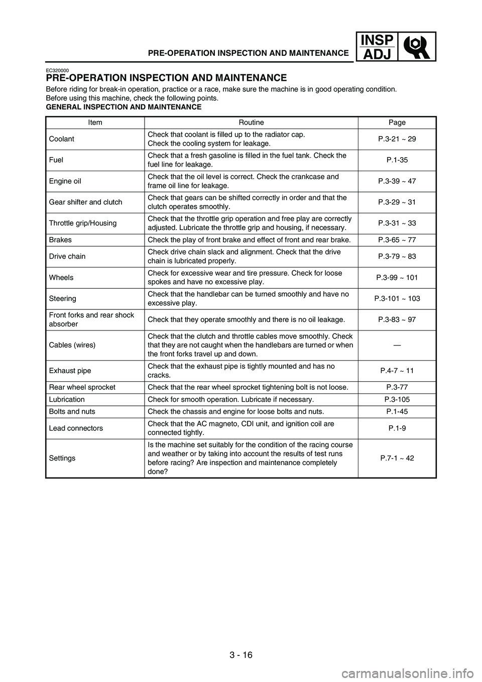
Before riding for break-in operation, practice or a race, make sure the machine is in good operating condition.
Before using this machine, check the following points.
GENERAL INSPECTION AND MAINTENANCE
Item Routine Page
CoolantCheck that coolant is filled up to the radiator cap.
Check the cooling system for leakage.P.3-21 ~ 29
FuelCheck that a fresh gasoline is filled in the fuel tank. Check the
fuel line for leakage.P.1-35
Engine oilCheck that the oil level is correct. Check the crankcase and
frame oil line for leakage.P.3-39 ~ 47
Gear shifter and clutchCheck that gears can be shifted correctly in order and that the
clutch operates smoothly.P.3-29 ~ 31
Throttle grip/HousingCheck that the throttle grip operation and free play are correctly
adjusted. Lubricate the throttle grip and housing, if necessary.P.3-31 ~ 33
Brakes Check the play of front brake and effect of front and rear brake. P.3-65 ~ 77
Drive chainCheck drive chain slack and alignment. Check that the drive
chain is lubricated properly.P.3-79 ~ 83
WheelsCheck for excessive wear and tire pressure. Check for loose
spokes and have no excessive play.P.3-99 ~ 101
SteeringCheck that the handlebar can be turned smoothly and have no
excessive play.P.3-101 ~ 103
Front forks and rear shock
absorberCheck that they operate smoothly and there is no oil leakage. P.3-83 ~ 97
Cables (wires)Check that the clutch and throttle cables move smoothly. Check
that they are not caught when the handlebars are turned or when
the front forks travel up and down.—
Exhaust pipeCheck that the exhaust pipe is tightly mounted and has no
cracks.P.4-7 ~ 11
Rear wheel sprocket Check that the rear wheel sprocket tightening bolt is not loose. P.3-77
Lubrication Check for smooth operation. Lubricate if necessary. P.3-105
Bolts and nuts Check the chassis and engine for loose bolts and nuts. P.1-45
Lead connectorsCheck that the AC magneto, CDI unit, and ignition coil are
connected tightly.P.1-9
SettingsIs the machine set suitably for the condition of the racing course
and weather or by taking into account the results of test runs
before racing? Are inspection and maintenance completely
done?P.7-1 ~ 42
Page 272 of 860
3 - 81
INSP
ADJ
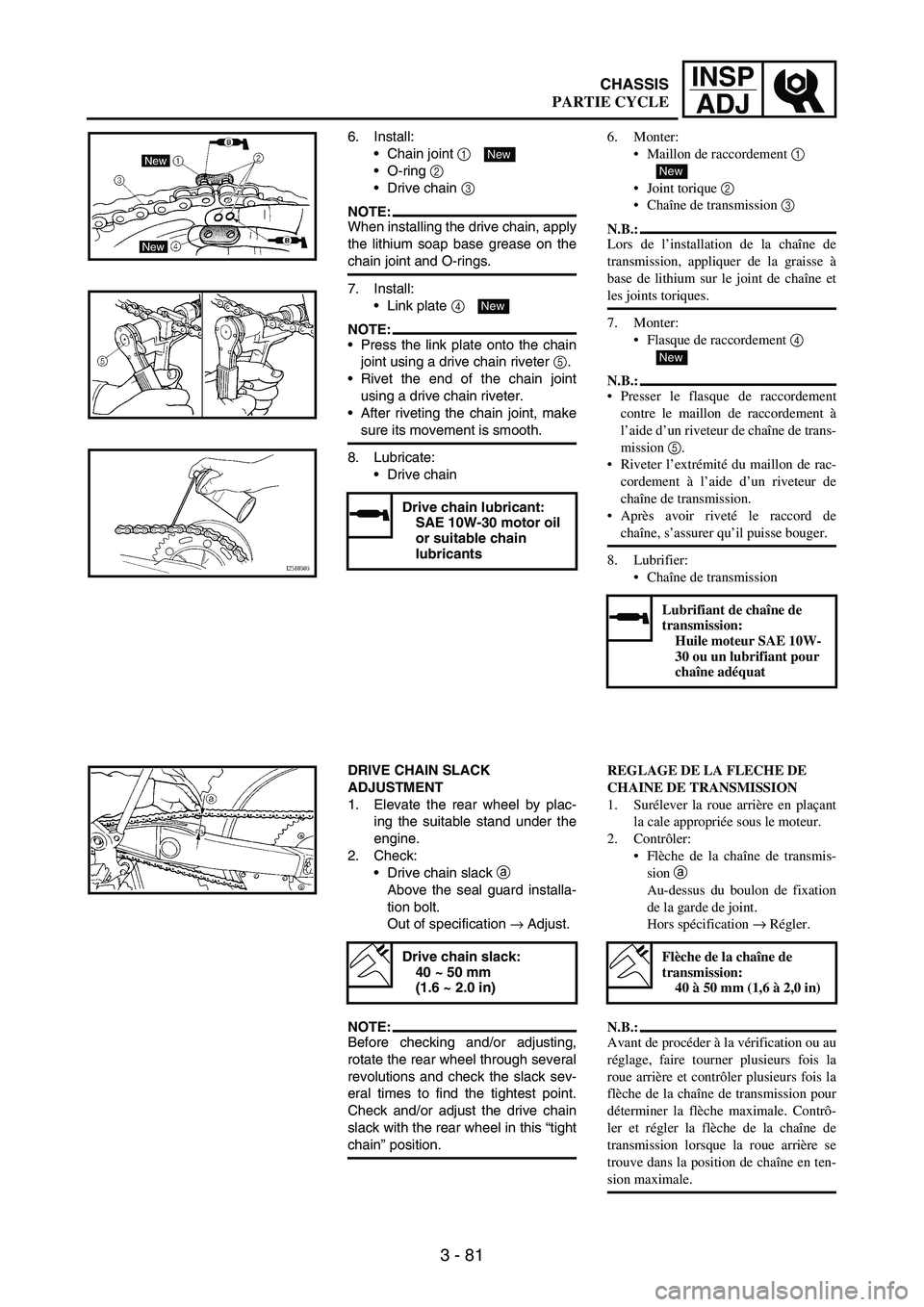
6. Install:
Chain joint
1
O-ring
2
Drive chain
3
NOTE:When installing the drive chain, apply
the lithium soap base grease on the
chain joint and O-rings.
7. Install:
Link plate
4
NOTE:Press the link plate onto the chain
joint using a drive chain riveter
5.
Rivet the end of the chain joint
using a drive chain riveter.
After riveting the chain joint, make
sure its movement is smooth.
8. Lubricate:
Drive chain
Drive chain lubricant:
SAE 10W-30 motor oil
or suitable chain
lubricants
New
New
DRIVE CHAIN SLACK
ADJUSTMENT
1. Elevate the rear wheel by plac-
ing the suitable stand under the
engine.
2. Check:
Drive chain slack
a
Above the seal guard installa-
tion bolt.
Out of specification
→ Adjust.
NOTE:Before checking and/or adjusting,
rotate the rear wheel through several
revolutions and check the slack sev-
eral times to find the tightest point.
Check and/or adjust the drive chain
slack with the rear wheel in this “tight
chain” position.
Drive chain slack:
40 ~ 50 mm
(1.6 ~ 2.0 in)
6. Monter:
Maillon de raccordement 1
Joint torique 2
Chaîne de transmission 3
N.B.:
Lors de l’installation de la chaîne de
transmission, appliquer de la graisse à
base de lithium sur le joint de chaîne et
les joints toriques.
7. Monter:
Flasque de raccordement 4
N.B.:
Presser le flasque de raccordement
contre le maillon de raccordement à
l’aide d’un riveteur de chaîne de trans-
mission 5.
Riveter l’extrémité du maillon de rac-
cordement à l’aide d’un riveteur de
chaîne de transmission.
Après avoir riveté le raccord de
chaîne, s’assurer qu’il puisse bouger.
8. Lubrifier:
Chaîne de transmission
Lubrifiant de chaîne de
transmission:
Huile moteur SAE 10W-
30 ou un lubrifiant pour
chaîne adéquat
New
New
REGLAGE DE LA FLECHE DE
CHAINE DE TRANSMISSION
1. Surélever la roue arrière en plaçant
la cale appropriée sous le moteur.
2. Contrôler:
Flèche de la chaîne de transmis-
sion a
Au-dessus du boulon de fixation
de la garde de joint.
Hors spécification → Régler.
N.B.:
Avant de procéder à la vérification ou au
réglage, faire tourner plusieurs fois la
roue arrière et contrôler plusieurs fois la
flèche de la chaîne de transmission pour
déterminer la flèche maximale. Contrô-
ler et régler la flèche de la chaîne de
transmission lorsque la roue arrière se
trouve dans la position de chaîne en ten-
sion maximale.
Flèche de la chaîne de
transmission:
40 à 50 mm (1,6 à 2,0 in)
CHASSIS
PARTIE CYCLE
Page 274 of 860
3 - 83
INSP
ADJ
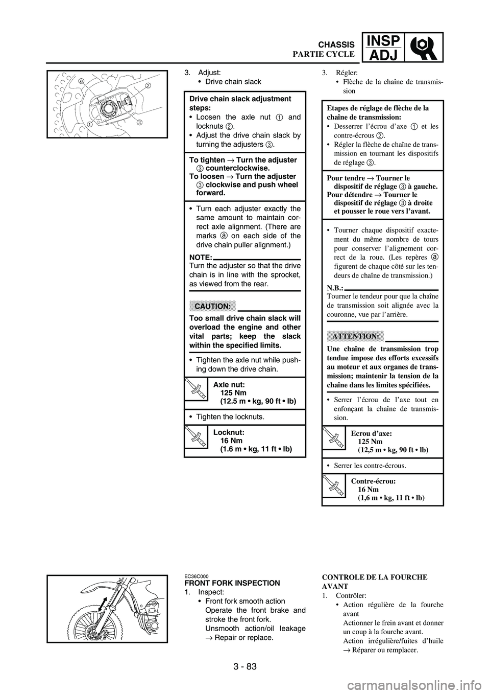
3. Adjust:
Drive chain slack
Drive chain slack adjustment
steps:
Loosen the axle nut
1 and
locknuts
2.
Adjust the drive chain slack by
turning the adjusters
3.
To tighten → Turn the adjuster
3 counterclockwise.
To loosen → Turn the adjuster
3 clockwise and push wheel
forward.
Turn each adjuster exactly the
same amount to maintain cor-
rect axle alignment. (There are
marks
a on each side of the
drive chain puller alignment.)
NOTE:Turn the adjuster so that the drive
chain is in line with the sprocket,
as viewed from the rear.
CAUTION:
Too small drive chain slack will
overload the engine and other
vital parts; keep the slack
within the specified limits.
Tighten the axle nut while push-
ing down the drive chain.
T R..
Axle nut:
125 Nm
(12.5 m kg, 90 ft lb)
Tighten the locknuts.
T R..
Locknut:
16 Nm
(1.6 m kg, 11 ft lb)
EC36C000FRONT FORK INSPECTION
1. Inspect:
Front fork smooth action
Operate the front brake and
stroke the front fork.
Unsmooth action/oil leakage
→ Repair or replace.
3. Régler:
Flèche de la chaîne de transmis-
sion
Etapes de réglage de flèche de la
chaîne de transmission:
Desserrer l’écrou d’axe 1 et les
contre-écrous 2.
Régler la flèche de chaîne de trans-
mission en tournant les dispositifs
de réglage 3.
Pour tendre → Tourner le
dispositif de réglage 3 à gauche.
Pour détendre → Tourner le
dispositif de réglage 3 à droite
et pousser le roue vers l’avant.
Tourner chaque dispositif exacte-
ment du même nombre de tours
pour conserver l’alignement cor-
rect de la roue. (Les repères a
figurent de chaque côté sur les ten-
deurs de chaîne de transmission.)
N.B.:
Tourner le tendeur pour que la chaîne
de transmission soit alignée avec la
couronne, vue par l’arrière.
ATTENTION:
Une chaîne de transmission trop
tendue impose des efforts excessifs
au moteur et aux organes de trans-
mission; maintenir la tension de la
chaîne dans les limites spécifiées.
Serrer l’écrou de l’axe tout en
enfonçant la chaîne de transmis-
sion.
T R..
Ecrou d’axe:
125 Nm
(12,5 m kg, 90 ft lb)
Serrer les contre-écrous.
T R..
Contre-écrou:
16 Nm
(1,6 m kg, 11 ft lb)
CONTROLE DE LA FOURCHE
AVANT
1. Contrôler:
Action régulière de la fourche
avant
Actionner le frein avant et donner
un coup à la fourche avant.
Action irrégulière/fuites d’huile
→ Réparer ou remplacer.
CHASSIS
PARTIE CYCLE
Page 598 of 860

5 - 21
CHASFRONT WHEEL AND REAR WHEEL
7. Install:
Left drive chain puller
1
Wheel axle
2
NOTE:Install the left drive chain puller,
and insert the wheel axle from left
side.
Apply the lithium soap base grease
on the wheel axle.
8. Install:
Right drive chain puller
1
Washer
2
Nut (wheel axle)
3
NOTE:Temporarily tighten the nut (wheel
axle) at this point.
9. Adjust:
Drive chain slack
a
Refer to “DRIVE CHAIN
SLACK ADJUSTMENT” sec-
tion in the CHAPTER 3.
Drive chain slack:
40 ~ 50 mm
(1.6 ~ 2.0 in)
10. Tighten:
Nut (wheel axle)
1
Locknut
2
T R..125 Nm (12.5 m · kg, 90 ft · lb)
T R..16 Nm (1.6 m · kg, 11 ft · lb)
7. Monter:
Tendeur gauche de chaîne de
transmission 1
Axe de roue 2
N.B.:
Monter le tendeur gauche de chaîne de
transmission, puis insérer l’axe de
roue du côté gauche.
Appliquer de la graisse à base de
savon au lithium sur l’axe de roue.
8. Monter:
Tendeur droit de chaîne de trans-
mission 1
Rondelle 2
Ecrou (axe de roue) 3
N.B.:
A ce stade, resserrer provisoirement
lécrou (axe de roue).
9. Régler:
Flèche de chaîne de transmission
a
Se reporter à la section
“REGLAGE DE LA FLECHE
DE CHAINE DE TRANSMIS-
SION” au CHAPITRE 3.
Flèche de chaîne de
transmission:
40 à 50 mm (1,6 à 2,0 in)
10. Serrer:
Ecrou (axe de roue) 1
Contre-écrou 2
T R..125 Nm (12,5 m · kg, 90 ft · lb)
T R..16 Nm (1,6 m · kg, 11 ft · lb)
ROUE AVANT ET ROUE ARRIERE