clock YAMAHA WR 250F 2003 Owners Manual
[x] Cancel search | Manufacturer: YAMAHA, Model Year: 2003, Model line: WR 250F, Model: YAMAHA WR 250F 2003Pages: 860, PDF Size: 35.16 MB
Page 85 of 860
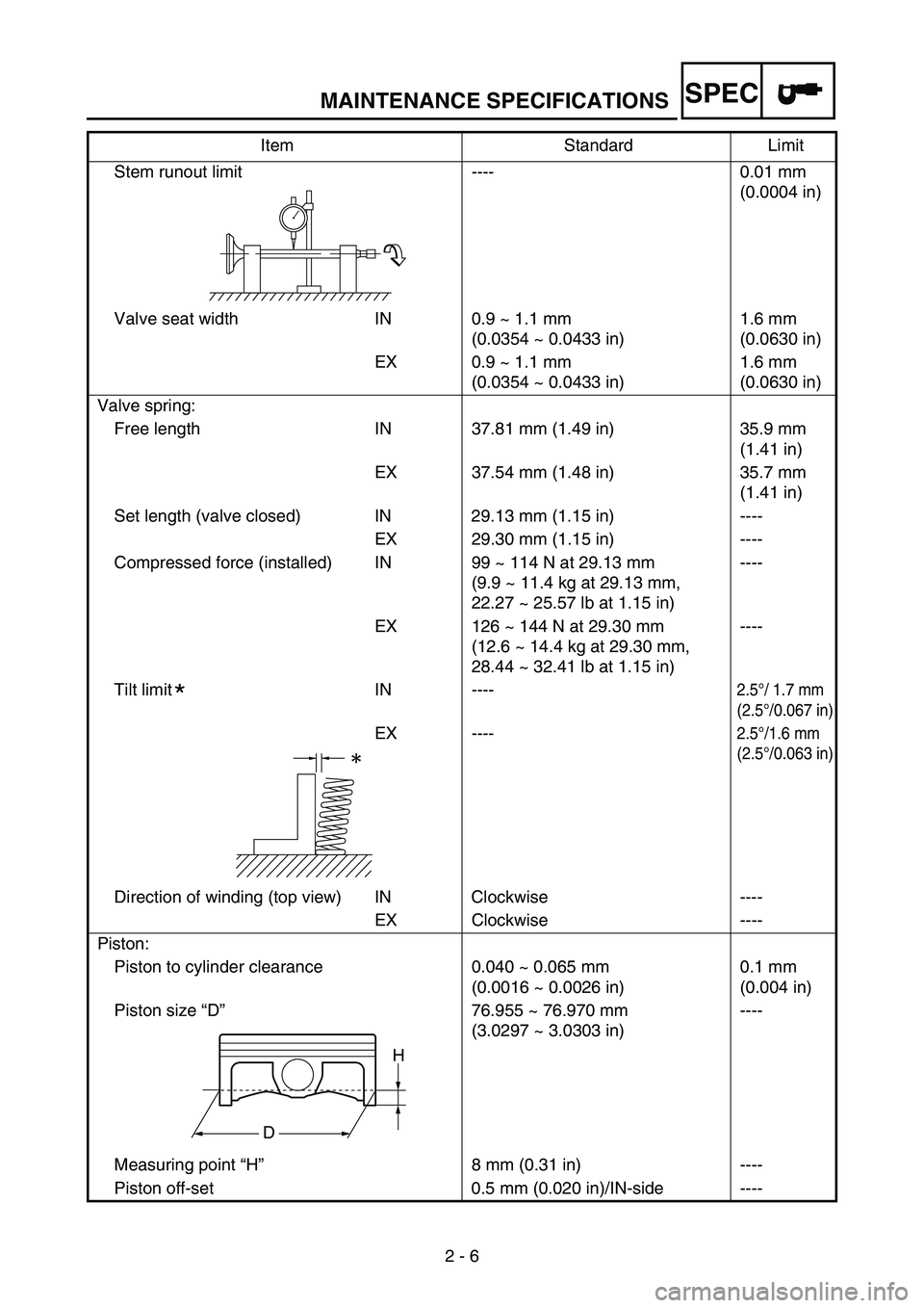
MAINTENANCE SPECIFICATIONS
2 - 6
SPEC
Stem runout limit ---- 0.01 mm
(0.0004 in)
Valve seat width IN 0.9 ~ 1.1 mm
(0.0354 ~ 0.0433 in)1.6 mm
(0.0630 in)
EX 0.9 ~ 1.1 mm
(0.0354 ~ 0.0433 in)1.6 mm
(0.0630 in)
Valve spring:
Free length IN 37.81 mm (1.49 in) 35.9 mm
(1.41 in)
EX 37.54 mm (1.48 in) 35.7 mm
(1.41 in)
Set length (valve closed) IN 29.13 mm (1.15 in) ----
EX 29.30 mm (1.15 in) ----
Compressed force (installed) IN 99 ~ 114 N at 29.13 mm
(9.9 ~ 11.4 kg at 29.13 mm,
22.27 ~ 25.57 lb at 1.15 in)----
EX 126 ~ 144 N at 29.30 mm
(12.6 ~ 14.4 kg at 29.30 mm,
28.44 ~ 32.41 lb at 1.15 in)----
Tilt limit IN ----
2.5°/ 1.7 mm
(2.5°/0.067 in)
EX ----2.5°/1.6 mm
(2.5°/0.063 in)
Direction of winding (top view) IN Clockwise ----
EX Clockwise ----
Piston:
Piston to cylinder clearance 0.040 ~ 0.065 mm
(0.0016 ~ 0.0026 in)0.1 mm
(0.004 in)
Piston size “D”76.955 ~ 76.970 mm
(3.0297 ~ 3.0303 in)----
Measuring point “H”8 mm (0.31 in) ----
Piston off-set 0.5 mm (0.020 in)/IN-side ----Item Standard Limit
*
H
D
Page 212 of 860
3 - 21
INSP
ADJ
EC350000
ENGINE
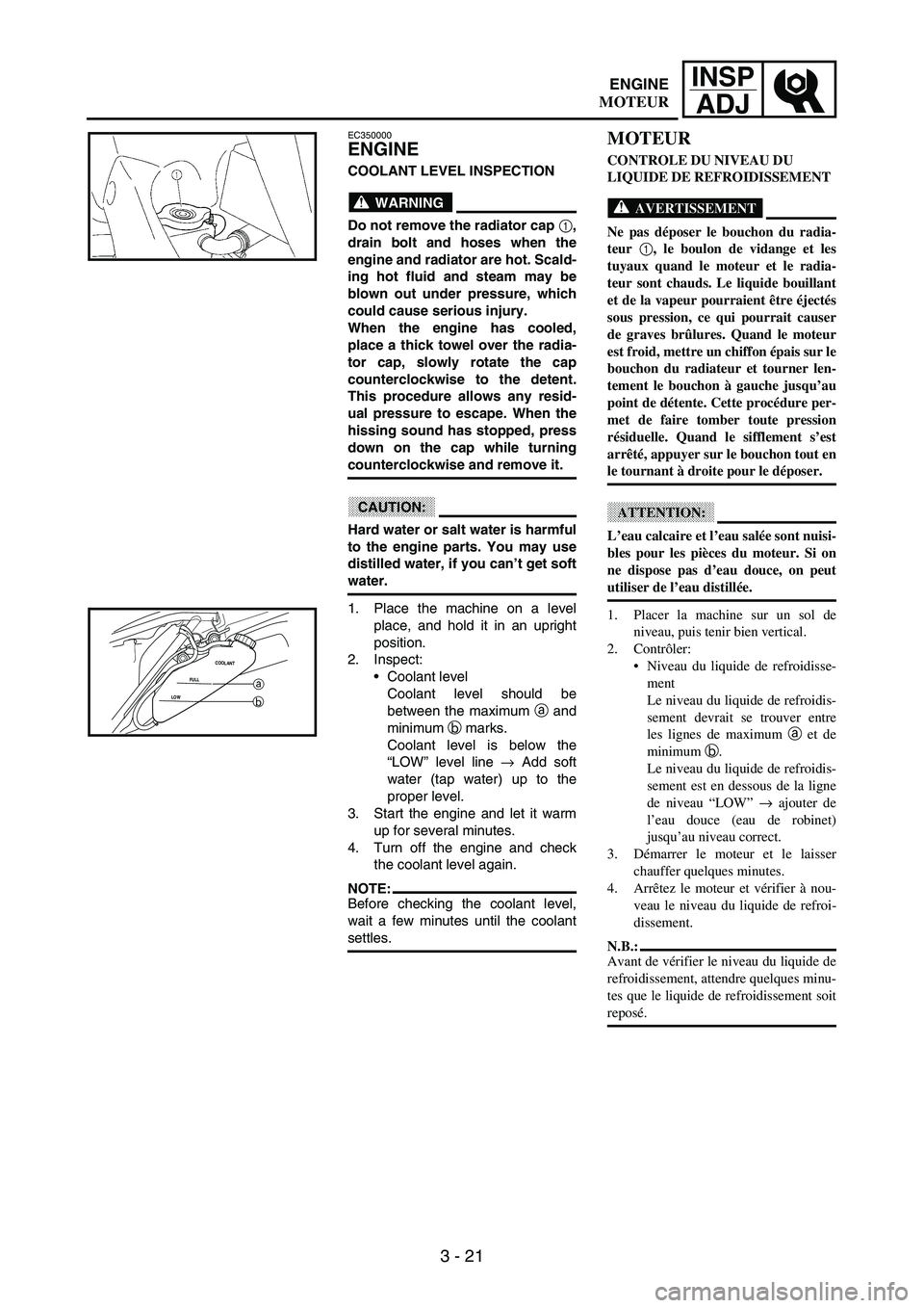
COOLANT LEVEL INSPECTION
WARNING
Do not remove the radiator cap 1,
drain bolt and hoses when the
engine and radiator are hot. Scald-
ing hot fluid and steam may be
blown out under pressure, which
could cause serious injury.
When the engine has cooled,
place a thick towel over the radia-
tor cap, slowly rotate the cap
counterclockwise to the detent.
This procedure allows any resid-
ual pressure to escape. When the
hissing sound has stopped, press
down on the cap while turning
counterclockwise and remove it.
CAUTION:
Hard water or salt water is harmful
to the engine parts. You may use
distilled water, if you can’t get soft
water.
1. Place the machine on a level
place, and hold it in an upright
position.
2. Inspect:
Coolant level
Coolant level should be
between the maximum
a and
minimum
b marks.
Coolant level is below the
“LOW” level line
→ Add soft
water (tap water) up to the
proper level.
3. Start the engine and let it warm
up for several minutes.
4. Turn off the engine and check
the coolant level again.
NOTE:Before checking the coolant level,
wait a few minutes until the coolant
settles.
LOWFULLCOOLANTa
b
MOTEUR
CONTROLE DU NIVEAU DU
LIQUIDE DE REFROIDISSEMENT
AVERTISSEMENT
Ne pas déposer le bouchon du radia-
teur 1
, le boulon de vidange et les
tuyaux quand le moteur et le radia-
teur sont chauds. Le liquide bouillant
et de la vapeur pourraient être éjectés
sous pression, ce qui pourrait causer
de graves brûlures. Quand le moteur
est froid, mettre un chiffon épais sur le
bouchon du radiateur et tourner len-
tement le bouchon à gauche jusqu’au
point de détente. Cette procédure per-
met de faire tomber toute pression
résiduelle. Quand le sifflement s’est
arrêté, appuyer sur le bouchon tout en
le tournant à droite pour le déposer.
ATTENTION:
L’eau calcaire et l’eau salée sont nuisi-
bles pour les pièces du moteur. Si on
ne dispose pas d’eau douce, on peut
utiliser de l’eau distillée.
1. Placer la machine sur un sol de
niveau, puis tenir bien vertical.
2. Contrôler:
Niveau du liquide de refroidisse-
ment
Le niveau du liquide de refroidis-
sement devrait se trouver entre
les lignes de maximum a et de
minimum b.
Le niveau du liquide de refroidis-
sement est en dessous de la ligne
de niveau “LOW” → ajouter de
l’eau douce (eau de robinet)
jusqu’au niveau correct.
3. Démarrer le moteur et le laisser
chauffer quelques minutes.
4. Arrêtez le moteur et vérifier à nou-
veau le niveau du liquide de refroi-
dissement.
N.B.:
Avant de vérifier le niveau du liquide de
refroidissement, attendre quelques minu-
tes que le liquide de refroidissement soit
reposé.
ENGINE
MOTEUR
Page 242 of 860

3 - 51
INSP
ADJ
3. Remove:
Right radiator
Refer to “RADIATOR” section
in the CHAPTER 4.
Carburetor
Refer to “CARBURETOR”
section in the CHAPTER 4.
Spark plug
Upper engine bracket
Cylinder head cover
Refer to “CAMSHAFTS” sec-
tion in the CHAPTER 4.
4. Remove:
Timing mark accessing screw
1
Crankshaft end accessing
screw
2
O-ring
5. Check:
Valve clearance
Out of specification
→ Adjust.
Valve clearance (cold):
Intake valve:
0.10 ~ 0.15 mm
(0.0039 ~ 0.0059 in)
Exhaust valve:
0.17 ~ 0.22 mm
(0.0067 ~ 0.0087 in)
Checking steps:
Turn the crankshaft counter-
clockwise with a wrench.
Align the T.D.C. mark
a on the
rotor with the align mark
b on
the crankcase cover when pis-
ton is at T.D.C. on compression
stroke.
NOTE:In order to be sure that the piston
is at Top Dead Center, the punch
mark
c on the exhaust camshaft
and the punch mark
d on the
intake camshaft must align with
the cylinder head surface, as
shown in the illustration.
Measure the valve clearance
e
using a feeler gauge
1.
NOTE:Record the measured reading if
the clearance is incorrect.
3. Déposer:
Radiateur de droite
Se reporter à la section “RADIA-
TEUR” au CHAPITRE 4.
Carburateur
Se reporter à la section “CARBU-
RATEUR” au CHAPITRE 4.
Bougie
Support supérieur de moteur
Couvre-culasse
Se reporter à la section
“ARBRES A CAMES” au CHA-
PITRE 4.
4. Déposer:
Vis d’accès du repère de distribu-
tion 1
Vis d’accès de l’extrémité de
vilebrequin 2
Joint torique
5. Contrôler:
Jeu de soupapes
Hors spécifications → Régler.
Jeu de soupapes (à froid):
Soupape d’admission:
0,10 à 0,15 mm
(0,0039 à 0,0059 in)
Soupape d’échappement:
0,17 à 0,22 mm
(0,0067 à 0,0087 in)
Etapes de la contrôle:
Faire tourner le vilebrequin dans le
sens inverse des aiguilles d’une
montre à l’aide d’une clé.
Aligner le repère PMH a du rotor
avec le repère d’alignement b du
couvercle de carter quand le piston
est au PMH sur sa course de com-
pression.
N.B.:
Les pistons sont au PMH lorsque le
repère d’alignement c de l’arbre à
cames d’échappement et le repère
d’alignement d de l’arbre à cames
d’admission s’alignent sur la surface
de la culasse, comme illustré.
Mesurer le jeu de soupapes e à
l’aide d’une jauge d’épaisseur 1.
N.B.:
Inscrire le relevé de la mesure si le
jeu n’est pas correct.
ENGINE
MOTEUR
Page 274 of 860
3 - 83
INSP
ADJ
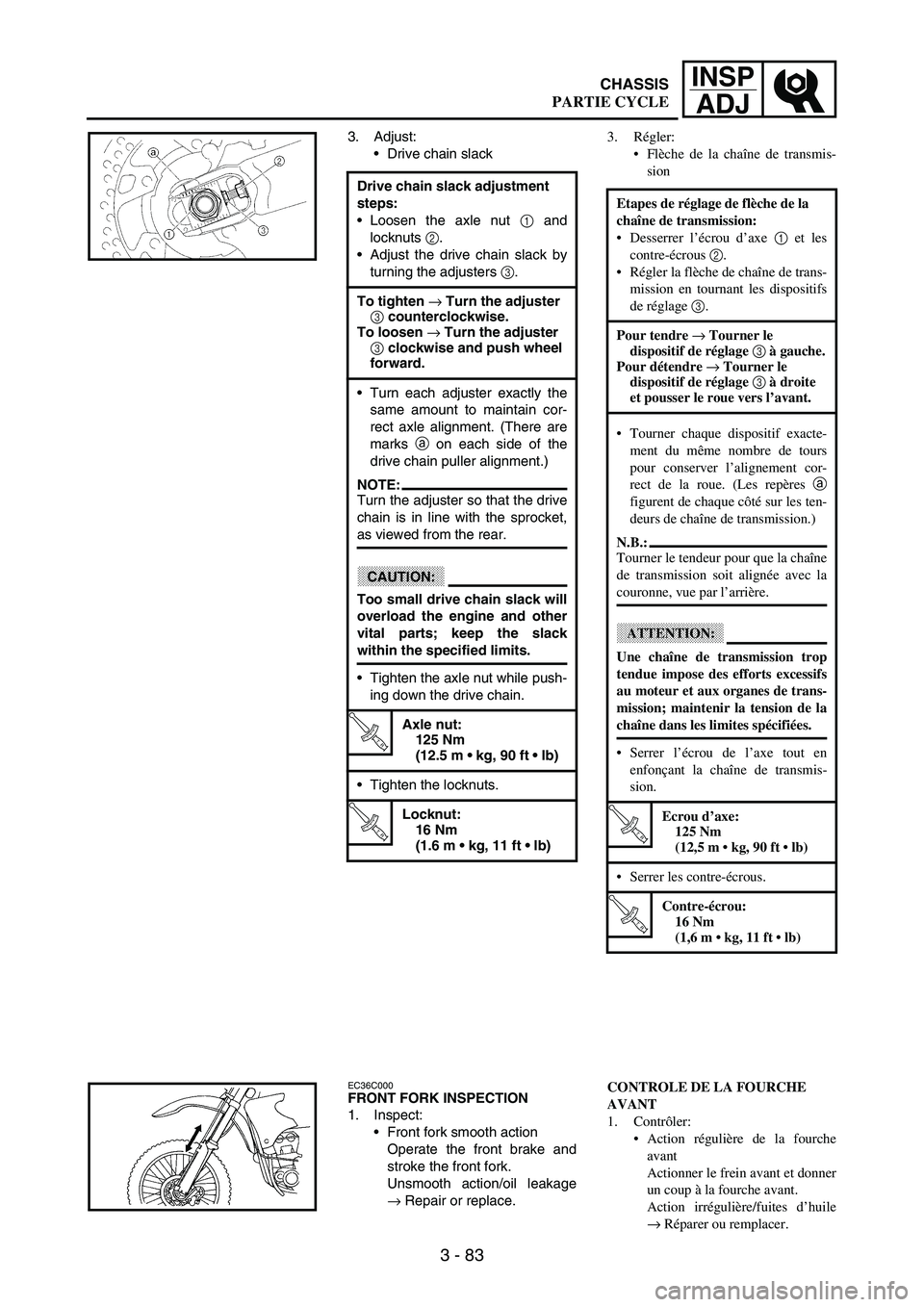
3. Adjust:
Drive chain slack
Drive chain slack adjustment
steps:
Loosen the axle nut
1 and
locknuts
2.
Adjust the drive chain slack by
turning the adjusters
3.
To tighten → Turn the adjuster
3 counterclockwise.
To loosen → Turn the adjuster
3 clockwise and push wheel
forward.
Turn each adjuster exactly the
same amount to maintain cor-
rect axle alignment. (There are
marks
a on each side of the
drive chain puller alignment.)
NOTE:Turn the adjuster so that the drive
chain is in line with the sprocket,
as viewed from the rear.
CAUTION:
Too small drive chain slack will
overload the engine and other
vital parts; keep the slack
within the specified limits.
Tighten the axle nut while push-
ing down the drive chain.
T R..
Axle nut:
125 Nm
(12.5 m kg, 90 ft lb)
Tighten the locknuts.
T R..
Locknut:
16 Nm
(1.6 m kg, 11 ft lb)
EC36C000FRONT FORK INSPECTION
1. Inspect:
Front fork smooth action
Operate the front brake and
stroke the front fork.
Unsmooth action/oil leakage
→ Repair or replace.
3. Régler:
Flèche de la chaîne de transmis-
sion
Etapes de réglage de flèche de la
chaîne de transmission:
Desserrer l’écrou d’axe 1 et les
contre-écrous 2.
Régler la flèche de chaîne de trans-
mission en tournant les dispositifs
de réglage 3.
Pour tendre → Tourner le
dispositif de réglage 3 à gauche.
Pour détendre → Tourner le
dispositif de réglage 3 à droite
et pousser le roue vers l’avant.
Tourner chaque dispositif exacte-
ment du même nombre de tours
pour conserver l’alignement cor-
rect de la roue. (Les repères a
figurent de chaque côté sur les ten-
deurs de chaîne de transmission.)
N.B.:
Tourner le tendeur pour que la chaîne
de transmission soit alignée avec la
couronne, vue par l’arrière.
ATTENTION:
Une chaîne de transmission trop
tendue impose des efforts excessifs
au moteur et aux organes de trans-
mission; maintenir la tension de la
chaîne dans les limites spécifiées.
Serrer l’écrou de l’axe tout en
enfonçant la chaîne de transmis-
sion.
T R..
Ecrou d’axe:
125 Nm
(12,5 m kg, 90 ft lb)
Serrer les contre-écrous.
T R..
Contre-écrou:
16 Nm
(1,6 m kg, 11 ft lb)
CONTROLE DE LA FOURCHE
AVANT
1. Contrôler:
Action régulière de la fourche
avant
Actionner le frein avant et donner
un coup à la fourche avant.
Action irrégulière/fuites d’huile
→ Réparer ou remplacer.
CHASSIS
PARTIE CYCLE
Page 342 of 860
4 - 17
ENGRADIATOR
EC456000HANDLING NOTE
WARNING
Do not remove the radiator cap
when the engine and radiator are
hot. Scalding hot fluid and steam
may be blown out under pressure,
which could cause serious injury.
When the engine has cooled, open
the radiator cap by the following
procedure:
Place a thick rag, like a towel, over
the radiator cap, slowly rotate the
cap counterclockwise to the
detent. This procedure allows any
residual pressure to escape. When
the hissing sound has stopped,
press down on the cap while turn-
ing counterclockwise and remove
it.
EC454000INSPECTIONEC444100Radiator
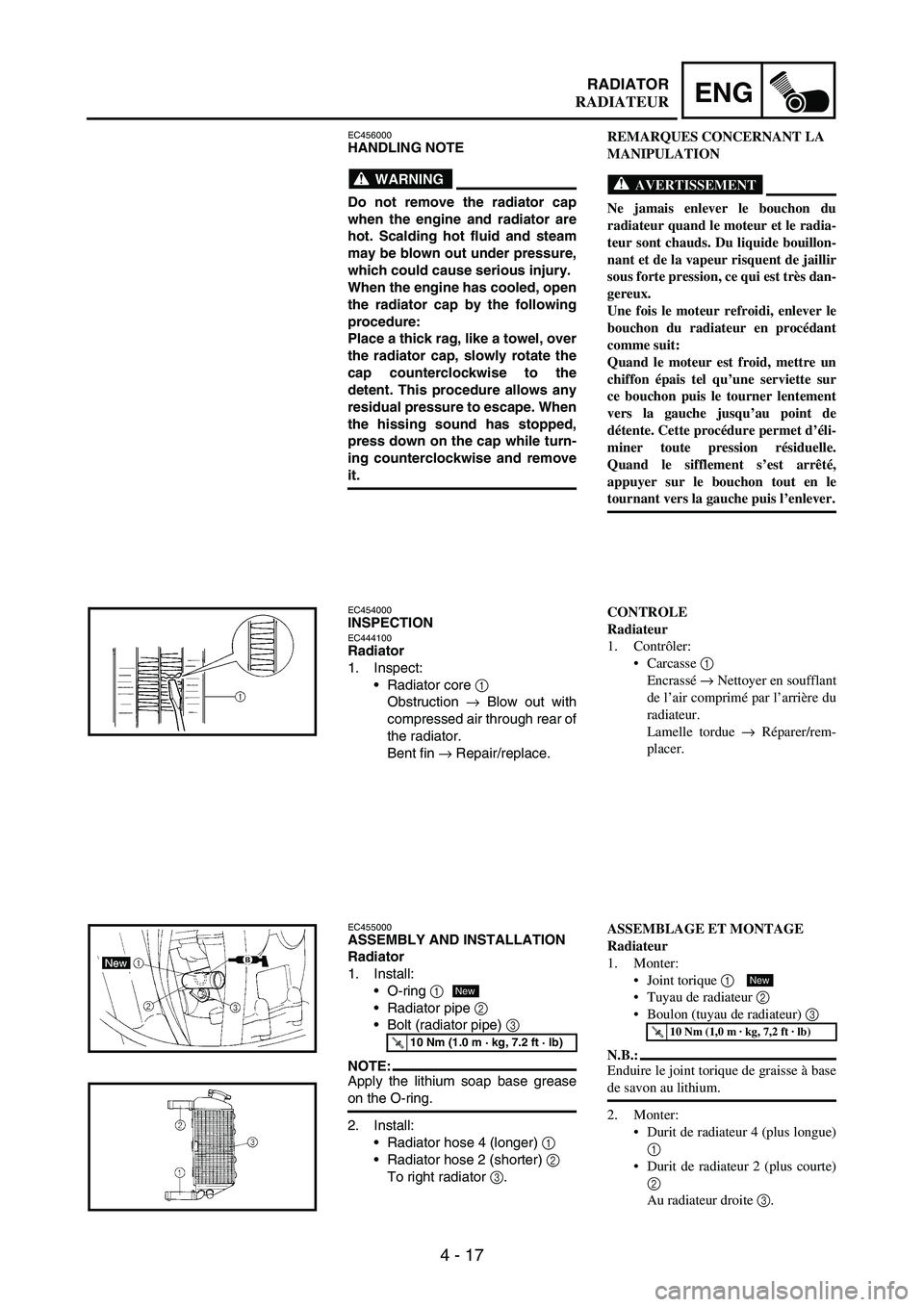
1. Inspect:
Radiator core
1
Obstruction
→ Blow out with
compressed air through rear of
the radiator.
Bent fin
→ Repair/replace.
EC455000ASSEMBLY AND INSTALLATION
Radiator
1. Install:
O-ring
1
Radiator pipe
2
Bolt (radiator pipe)
3
NOTE:Apply the lithium soap base grease
on the O-ring.
2. Install:
Radiator hose 4 (longer)
1
Radiator hose 2 (shorter)
2
To right radiator
3.
T R..10 Nm (1.0 m · kg, 7.2 ft · lb)
New
REMARQUES CONCERNANT LA
MANIPULATION
AVERTISSEMENT
Ne jamais enlever le bouchon du
radiateur quand le moteur et le radia-
teur sont chauds. Du liquide bouillon-
nant et de la vapeur risquent de jaillir
sous forte pression, ce qui est très dan-
gereux.
Une fois le moteur refroidi, enlever le
bouchon du radiateur en procédant
comme suit:
Quand le moteur est froid, mettre un
chiffon épais tel qu’une serviette sur
ce bouchon puis le tourner lentement
vers la gauche jusqu’au point de
détente. Cette procédure permet d’éli-
miner toute pression résiduelle.
Quand le sifflement s’est arrêté,
appuyer sur le bouchon tout en le
tournant vers la gauche puis l’enlever.
CONTROLE
Radiateur
1. Contrôler:
Carcasse 1
Encrassé → Nettoyer en soufflant
de l’air comprimé par l’arrière du
radiateur.
Lamelle tordue → Réparer/rem-
placer.
ASSEMBLAGE ET MONTAGE
Radiateur
1. Monter:
Joint torique 1
Tuyau de radiateur 2
Boulon (tuyau de radiateur) 3
N.B.:
Enduire le joint torique de graisse à base
de savon au lithium.
2. Monter:
Durit de radiateur 4 (plus longue)
1
Durit de radiateur 2 (plus courte)
2
Au radiateur droite 3.
T R..10 Nm (1,0 m · kg, 7,2 ft · lb)
New
RADIATEUR
Page 384 of 860

4 - 59
ENGCAMSHAFTS
REMOVAL POINTS
Camshaft
1. Remove:
Timing mark accessing screw
1
Crankshaft end accessing
screw
2
2. Align:
T.D.C. mark
With align mark.
Checking steps:
Turn the crankshaft counter-
clockwise with a wrench.
Align the T.D.C. mark
a on the
rotor with the align mark
b on
the crankcase cover when pis-
ton is at T.D.C. on compression
stroke.
NOTE:In order to be sure that the piston
is at Top Dead Center, the punch
mark
c on the exhaust camshaft
and the punch mark
d on the
intake camshaft must align with
the cylinder head surface, as
shown in the illustration.
3. Remove:
Timing chain tensioner cap
bolt
1
Timing chain tensioner
2
Gasket
1
2
4. Remove:
Bolt (camshaft cap)
1
Camshaft cap
2
Clip
NOTE:Remove the bolts (camshaft cap) in a
crisscross pattern, working from the
outside in.
CAUTION:
The bolts (camshaft cap) must be
removed evenly to prevent dam-
age to the cylinder head, cam-
shafts or camshaft caps.
POINTS DE DEPOSE
Arbre à cames
1. Déposer:
Vis d’accès du repère de distribu-
tion 1
Vis d’accès de l’extrémité de
vilebrequin 2
2. Aligner:
Repère de PMH
Avec repère d’alignement.
Etapes de la contrôler:
Tourner le vilebrequin à l’aide
d’une clé dans le sens inverse des
aiguilles d’une montre.
Aligner le repère de PMH a sur le
rotor le repère d’alignement b sur
le couvercle du carter quand le pis-
ton se trouve au Point Mort Haut
(PMH) sur la courge de compres-
sion.
N.B.:
Les pistons sont au PMH lorsque le
repère d’alignement c de l’arbre à
cames d’échappement et le repère
d’alignement d de l’arbr à cames
d’admission s’alignent sur la surface
de la culasse, comme illustré.
3. Déposer:
Boulon capuchon du tendeur de
la chaîne de distribution 1
Tendeur de la chaîne de distribu-
tion 2
Joint
4. Déposer:
Boulon
(chapeaux d’arbre à cames) 1
Chapeaux d’arbre à cames 2
Clip
N.B.:
Enlever les boulons (chapeaux d’arbre à
cames) en suivant un ordre entrecroisé et
en commençant par l’intérieur.
ATTENTION:
Les boulons (chapeaux d’arbre à
cames) doivent être enlevés uniformé-
ment pour éviter d’abîmer la culasse,
l’arbre à cames ou les chapeaux
d’arbre à cames.
ARBRES A CAMES
Page 390 of 860

4 - 65
ENGCAMSHAFTS
Decompression system
1. Check:
Decompression system
Checking steps:
Check that the decompression
mechanism cam
1 moves
smoothly.
Check that the decompression
mechanism cam lever pin
2
projects from the camshaft.
Timing chain tensioner
1. Check:
While pressing the tensioner
rod lightly with fingers, use a
thin screwdriver
1 and wind
the tensioner rod up fully
clockwise.
When releasing the screw-
driver by pressing lightly with
fingers, make sure that the
tensioner rod will come out
smoothly.
If not, replace the tensioner
assembly.
ASSEMBLY AND INSTALLATION
Camshaft
1. Install:
Exhaust camshaft
1
Intake camshaft
2
Installation steps:
Turn the crankshaft counter-
clockwise with a wrench.
NOTE:Apply the molybdenum disulfide
oil on the camshafts.
Apply the engine oil on the
decompression system.
Squeezing the decompression
lever allows the crankshaft to
be turned easily.
Align the T.D.C. mark
a on the
rotor with the align mark
b on
the crankcase cover when pis-
ton is at T.D.C. on compression
stroke.
Système de décompression
1. Contrôler:
Système de décompression
Points à contrôler:
S’assurer que la came de décom-
presseur 1 tourne en douceur.
S’assurer que la goupille du levier
de la came de décompresseur 2
ressorte de l’arbre à cames.
Tendeur de la chaîne de distribution
1. Contrôler:
Tout en comprimant légèrement
la tige du tendeur à l’aide du
doigt, la visser complètement
(tourner dans le sens des aiguilles
d’une montre) en se servant d’un
tournevis fin 1.
Après avoir retiré le tournevis en
appuyant légèrement du doigt,
vérifier si la tige du tendeur sort
sans problème.
Si elle ne sort pas, remplacer le
tendeur.
ASSEMBLAGE ET MONTAGE
Arbre à cames
1. Monter:
Arbre à cames d’échappement 1
Arbre à cames d’admission 2
Etapes de montage:
Tourner le vilebrequin à l’aide
d’une clé dans le sens inverse des
aiguilles d’une montre.
N.B.:
Appliquer de l’huile au bisulfure
de molybdène sur les arbres à
cames.
Appliquer de l’huile moteur sur le
système de décompression.
Actionner le levier de décompres-
sion a fin de faciliter la rotation du
rilebrequin.
Aligner le repère de PMH a sur le
rotor le repère d’alignement b sur
le couvercle du carter quand le pis-
ton se trouve au Point Mort Haut
(PMH) sur la courge de compres-
sion.
ARBRES A CAMES
Page 392 of 860

4 - 67
ENGCAMSHAFTS
Fit the timing chain
3 onto both
camshaft sprockets and install
the camshafts on the cylinder
head.
NOTE:The camshafts should be installed
onto the cylinder head so that the
punch mark
c on the exhaust
camshaft and the punch mark
d
on the intake camshaft must align
with the cylinder head surface, as
shown in the illustration.
CAUTION:
Do not turn the crankshaft dur-
ing the camshaft installation.
Damage or improper valve tim-
ing will result.
Install the clips, camshaft caps
4 and bolts (camshaft cap)
5.
T R..
Bolt (camshaft cap):
10 Nm
(1.0 m kg, 7.2 ft lb)
NOTE:Before removing the clips, cover
the cylinder head with a clean
rag to prevent the clips from into
the cylinder head cavity.
Apply the engine oil on the
thread and contact surface of the
bolts (camshaft cap).
Tighten the bolts (camshaft cap)
in a crisscross pattern.
CAUTION:
The bolts (camshaft cap) must
be tightened evenly, or damage
to the cylinder head, camshaft
caps, and camshaft will result.
2. Install:
Timing chain tensioner
Installation steps:
While pressing the tensioner
rod lightly with fingers, use a
thin screwdriver and wind the
tensioner rod up fully clockwise.
Placer la chaîne de distribution 3
sur les deux pignons d’arbre à
cames et installer les arbres à
cames dans la culasse.
N.B.:
Monter les arbres à cames dans la
culasse en veillant à ce que le repère
poinçonné c de l’arbre à cames
d’échappment et le repère poinçonné
d de l’arbre à cames d’admission
s’alignent sur la surface de la culasse,
comme illustré.
ATTENTION:
Ne pas faire tourner le vilebrequin
pendant la mise en place des arbres
à cames. Cela risquerait d’entraî-
ner une mauvaise synchronisation
des soupapes et de les endomma-
ger.
Monter, les clips les et chapeaux
d’arbre à cames 4 et les boulons
(chapeau d’arbre d’cames) 5.
T R..
Boulon (chapeau d’arbre à
cames):
10 Nm
(1,0 m kg, 7,2 ft lb)
N.B.:
Avant de retirer les clips, couvrir la
culasse d’un chiffon propre pour
empêcher qu’ils ne tombent dans la
cavité de la culasse.
Appliquer de l’huile moteur sur
toute la surface des boulons (cha-
peau d’arbre à cames).
Serrer les boulons (chapeau d’arbre
à cames) en suivant un ordre entre-
croisé.
ATTENTION:
Il importe de serrer les boulons
(chapeau d’arbre à cames) unifor-
mément pour éviter d’endomma-
ger la culasse, les chapeaux d’arbre
à cames et l’arbre à cames.
2. Monter:
Tendeur de la chaîne de distribu-
tion
Etapes du montage:
Tout en comprimant légèrement la
tige du tendeur à l’aide du doigt, la
visser complètement (tourner dans
le sens des aiguilles d’une montre)
en se servant d’un tournevis fin.
ARBRES A CAMES
Page 394 of 860
4 - 69
ENGCAMSHAFTS
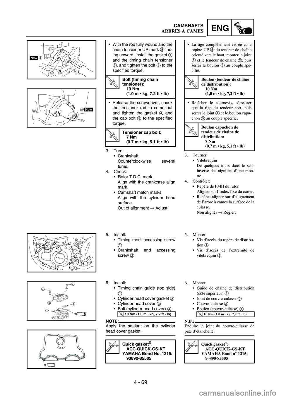
3. Turn:
Crankshaft
Counterclockwise several
turns.
4. Check:
Rotor T.D.C. mark
Align with the crankcase align
mark.
Camshaft match marks
Align with the cylinder head
surface.
Out of alignment
→ Adjust. With the rod fully wound and the
chain tensioner UP mark
a fac-
ing upward, install the gasket
1
and the timing chain tensioner
2, and tighten the bolt
3 to the
specified torque.
T R..
Bolt (timing chain
tensioner):
10 Nm
(1.0 m kg, 7.2 ft lb)
Release the screwdriver, check
the tensioner rod to come out
and tighten the gasket
4 and
the cap bolt
5 to the specified
torque.
T R..
Tensioner cap bolt:
7 Nm
(0.7 m kg, 5.1 ft lb)
5
4New
5. Install:
Timing mark accessing screw
1
Crankshaft end accessing
screw
2
6. Install:
Timing chain guide (top side)
1
Cylinder head cover gasket
2
Cylinder head cover
3
Bolt (cylinder head cover)
4
NOTE:Apply the sealant on the cylinder
head cover gasket.
T R..10 Nm (1.0 m · kg, 7.2 ft · lb)
Quick gasket®:
ACC-QUICK-GS-KT
YAMAHA Bond No. 1215:
90890-85505
3. Tourner:
Vilebrequin
De quelques tours dans le sens
inverse des aiguilles d’une mon-
tre.
4. Contrôler:
Repère de PMH du rotor
Aligner sur l’index fixe du carter.
Repères aligner sur d’alignement
de l’arbre à cames la surface de la
culasse.
Non alignés → Régler. La tige complètement vissée et le
repère UP a du tendeur de chaîne
orienté vers le haut, monter le joint
1 et le tendeur de chaîne 2, puis
serrer le boulon 3 au couple spé-
cifié.
T R..
Boulon (tendeur de chaîne
de distribution):
10 Nm
(1,0 m kg, 7,2 ft lb)
Relâcher le tournevis, s’assurer
que la tige du tendeur sort, puis
serrer le joint 4
et le boulon capu-
chon 5 au couple spécifié.
T R..
Boulon capuchon de
tendeur de chaîne de
distribution:
7 Nm
(0,7 m kg, 5,1 ft lb)
5. Monter:
Vis d’accès du repère de distribu-
tion 1
Vis d’accès de l’extrémité de
vilebrequin 2
6. Monter:
Guide de chaîne de distribution
(côté supérieur) 1
Joint de couvre-culasse 2
Couvre-culasse 3
Boulon (couvre-culasse) 4
N.B.:
Enduire le joint du couvre-culasse de
pâte d’étanchéité.
T R..10 Nm (1,0 m · kg, 7,2 ft · lb)
Quick gasket®:
ACC-QUICK-GS-KT
YAMAHA Bond n° 1215:
90890-85505
ARBRES A CAMES
Page 502 of 860
4 - 177
ENGKICK SHAFT AND SHIFT SHAFT
REMOVAL POINTS
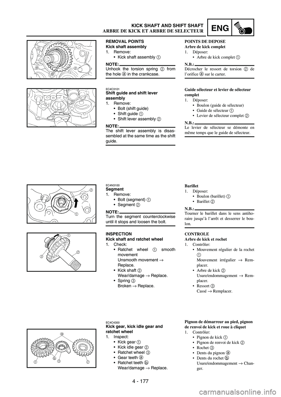
Kick shaft assembly
1. Remove:
Kick shaft assembly
1
NOTE:Unhook the torsion spring
2 from
the hole
a in the crankcase.
EC4C3101Shift guide and shift lever
assembly
1. Remove:
Bolt (shift guide)
Shift guide
1
Shift lever assembly
2
NOTE:The shift lever assembly is disas-
sembled at the same time as the shift
guide.
EC4N3100Segment
1. Remove:
Bolt (segment)
1
Segment
2
NOTE:Turn the segment counterclockwise
until it stops and loosen the bolt.
INSPECTION
Kick shaft and ratchet wheel
1. Check:
Ratchet wheel
1 smooth
movement
Unsmooth movement
→
Replace.
Kick shaft
2
Wear/damage
→ Replace.
Spring
3
Broken
→ Replace.
EC4C4300Kick gear, kick idle gear and
ratchet wheel
1. Inspect:
Kick gear
1
Kick idle gear
2
Ratchet wheel
3
Gear teeth
a
Ratchet teeth
b
Wear/damage
→ Replace.
POINTS DE DEPOSE
Arbre de kick complet
1. Déposer:
Arbre de kick complet 1
N.B.:
Décrocher le ressort de torsion 2 de
l’orifice a sur le carter.
Guide sélecteur et levier de sélecteur
complet
1. Déposer:
Boulon (guide de sélecteur)
Guide de sélecteur 1
Levier de sélecteur complet 2
N.B.:
Le levier de sélecteur se démonte en
même temps que le guide de sélecteur.
Barillet
1. Déposer:
Boulon (barillet) 1
Barillet 2
N.B.:
Tourner le barillet dans le sens antiho-
raire jusqu’à l’arrêt et desserrer le bou-
lon.
CONTROLE
Arbre de kick et rochet
1. Contrôler:
Mouvement régulier de la rochet
1
Mouvement irrégulier → Rem-
placer.
Arbre de kick 2
Usure/endommagement → Rem-
placer.
Ressort 3
Cassé → Remplacer.
Pignon de démarreur au pied, pignon
de renvoi de kick et roue à cliquet
1. Contrôler:
Pignon de kick 1
Pignon de renvoi de kick 2
Rochet 3
Dents du pignon a
Dents du rochet b
Usure/endommagement → Chan-
ger.
ARBRE DE KICK ET ARBRE DE SELECTEUR