engine YAMAHA WR 250F 2003 Owners Manual
[x] Cancel search | Manufacturer: YAMAHA, Model Year: 2003, Model line: WR 250F, Model: YAMAHA WR 250F 2003Pages: 860, PDF Size: 35.16 MB
Page 6 of 860
IMPORTANT NOTICE
THIS MACHINE IS DESIGNED
STRICTLY FOR COMPETITION
USE, ONLY ON A CLOSED
COURSE. It is illegal for this machine
to be operated on any public street,
road, or highway. Off-road use on
public lands may also be illegal.
Please check local regulations
before riding.
1. THIS MACHINE IS TO BE
OPERATED BY AN EXPERI-
ENCED RIDER ONLY.
Do not attempt to operate
this machine at maximum
power until you are totally
familiar with its characteris-
tics.
2. THIS MACHINE IS
DESIGNED TO BE RIDDEN
BY THE OPERATOR ONLY.
Do not carry passengers on
this machine.
3. ALWAYS WEAR PROTEC-
TIVE APPAREL.
When operating this
machine, always wear an
approved helmet with gog-
gles or a face shield. Also
wear heavy boots, gloves,
and protective clothing.
Always wear proper fitting
clothing that will not be
caught in any of the moving
parts or controls of the
machine.
4. ALWAYS MAINTAIN YOUR
MACHINE IN PROPER
WORKING ORDER.
For safety and reliability,
the machine must be pro-
erly maintained. Always
perform the pre-operation
checks indicated in this
manual. Correcting a
mechanical problem before
you ride may prevent an
accident.
5. GASOLINE IS HIGHLY
FLAMMABLE.
Always turn off the engine
while refueling. Take care
to not spill any gasoline on
the engine or exhaust sys-
tem. Never refuel in the
vicinity of an open flame, or
while smoking.
SAFETY INFORMATION
NOTICE
IMPORTANTE
CETTE MACHINE EST STRICTE-
MENT DESTINEE A LA COMPETI-
TION, UNIQUEMENT SUR CIRCUIT
FERME. Il est illégal d’utiliser cette
machine sur une rue, route ou artère
publique. L’utilisation de tous-terrains
sur les domaines publics peut également
être illégale. Prière de vérifier les lois
locales avant de conduire.
1. CETTE MACHINE NE DOIT
ETRE UTILISEE QUE PAR
UN CONDUCTEUR EXPERI-
MENTE.
Ne pas essayer d’utiliser cette
machine à sa puissance maxi-
mum tant que vous n’êtes pas
familier avec ses caractéristi-
ques.
2. CETTE MACHINE N’EST
CONCUE POUR ETRE UTI-
LISEE QUE PAR LE CON-
DUCTEUR.
Ne pas prendre de passagers
sur cette machine.
3. TOUJOURS PORTER UN
EQUIPEMENT DE PROTEC-
TION.
Lors de l’utilisation de cette
machine, toujours porter un
casque homologué avec des
lunettes ou un protège-visage.
Porter également de grosses
bottes, des gants et des vête-
ments de protection. Toujours
porter des vêtements de taille
correcte qui ne seront pas pris
dans une des pièces ou com-
mandes mobiles de la machine.
4. TOUJOURS GARDER
VOTRE MACHINE EN BON
ETAT DE MARCHE.
La machine doit être correcte-
ment entretenue pour des
questions de sécurité et de fia-
bilité. Toujours effectuer les
opérations précédant l’utilisa-
tion indiquées dans ce manuel.
La correction d’un problème
mécanique avant la conduite
peut empêcher un éventuel
accident.
5. L’ESSENCE EST HAUTE-
MENT INFLAMMABLE.
Toujours arrêter le moteur en
faisant le plein. Faire attention
à ne pas verser d’essence sur le
moteur ou le pot d’échappe-
ment. Ne jamais faire le plein
au voisinage d’une flamme une
ou en fumant.
INFORMATION DE SECURITE
Page 8 of 860
6. GASOLINE CAN CAUSE
INJURY.
If you should swallow some
gasoline, inhale excess
gasoline vapors, or allow
any gasoline to get into
your eyes, contact a doctor
immediately. If any gaso-
line spills onto your skin or
clothing, immediately wash
skin areas with soap and
water, and change your
clothes.
7. ONLY OPERATE THE
MACHINE IN AN AREA
WITH ADEQUATE VENTI-
LATION.
Never start the engine or let
it run for any length of time
in an enclosed area.
Exhaust fumes are poison-
ous. These fumes contain
carbon monoxide, which by
itself is odorless and color-
less. Carbon monoxide is a
dangerous gas which can
cause unconsciousness or
can be lethal.
8. PARK THE MACHINE
CAREFULLY; TURN OFF
THE ENGINE.
Always turn off the engine
if you are going to leave the
machine. Do not park the
machine on a slope or soft
ground as it may fall over.
9. THE ENGINE, EXHAUST
PIPE, MUFFLER, AND OIL
TANK WILL BE VERY HOT
AFTER THE ENGINE HAS
BEEN RUN.
Be careful not to touch
them or to allow any cloth-
ing item to contact them
during inspection or repair.
10. PROPERLY SECURE THE
MACHINE BEFORE TRANS-
PORTING IT.
When transporting the
machine in another vehicle,
always be sure it is prop-
erly secured and in an
upright position and that
the fuel cock is in the
“OFF” position. Otherwise,
fuel may leak out of the car-
buretor or fuel tank.6. L’ESSENCE PEUT CAUSER
DES BLESSURES.
Si vous avalez de l’essence, res-
pirez des vapeurs d’essence en
excès ou laissez de l’essence
pénétrer dans vos yeux, pren-
dre immédiatement contact
avec un médecin. Si de
l’essence est renversée sur
votre peau ou vos vêtements,
laver immédiatement la peau
avec du savon et de l’eau et
changer de vêtements.
7. N’UTILISER LA MACHINE
QUE DANS UN ENDROIT
AVEC AERATION ADE-
QUATE.
Ne jamais mettre le moteur en
marche ni le laisser tourner
pendant un quelconque laps de
temps dans un endroit clos.
Les fumées d’échappement
sont toxiques. Ces fumées con-
tiennent du monoxyde de car-
bone incolore et inodore. Le
monoxyde de carbone est un
gaz toxique dangereux qui
peut entraîner la perte de con-
naissance ou être mortel.
8. STATIONNER AVEC SOIN
LA MACHINE ET ARRE-
TER LE MOTEUR.
Toujours arrêter le moteur si
vous devez abandonner la
machine. Ne pas stationner en
pente ou sur un sol mou ou elle
pourrait se renverser.
9. LE MOTEUR, LE SYSTÈME
D’ÉCHAPPEMENT ET LE
RÉSERVOIR D’HUILE
SONT TRÈS CHAUDS
LORSQUE LE MOTEUR A
TOURNÉ.
Bien veiller à ne pas toucher
ces organes et éviter tout con-
tact avec les vêtements pen-
dant l’inspection ou la
réparation du véhicule.
10. FIXER SOLIDEMENT LA
MACHINE AVANT DE LA
TRANSPORTER.
En cas de transport de la
machine sur un autre véhicule,
toujours s’assurer qu’elle est
correctement fixée et posée sur
ses roues et que le robinet de
carburant est dans la position
OFF (fermé). Sans quoi il peut
y avoir des fuites du carbura-
teur et du réservoir.
Page 12 of 860
EC080000
HOW TO USE THIS
MANUAL
EC081000
PARTICULARLY
IMPORTANT
INFORMATION
The Safety Alert Symbol means
ATTENTION! BECOME ALERT!
YOUR SAFETY IS INVOLVED!
Failure to follow WARNING instruc-
tions could result in severe injury or
death to the machine operator, a
bystander, or a person inspecting or
repairing the machine.
A CAUTION indicates special pre-
cautions that must be taken to avoid
damage to the machine.
NOTE:
A NOTE provides key information to
make procedures easier or clearer.
WARNING
CAUTION:
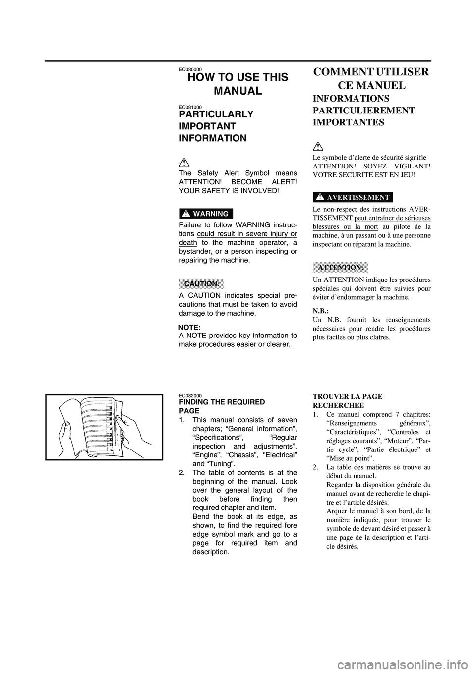
EC082000FINDING THE REQUIRED
PAGE
1. This manual consists of seven
chapters; “General information”,
“Specifications”, “Regular
inspection and adjustments”,
“Engine”, “Chassis”, “Electrical”
and “Tuning”.
2. The table of contents is at the
beginning of the manual. Look
over the general layout of the
book before finding then
required chapter and item.
Bend the book at its edge, as
shown, to find the required fore
edge symbol mark and go to a
page for required item and
description.
COMMENT UTILISER
CE MANUEL
INFORMATIONS
PARTICULIEREMENT
IMPORTANTES
Le symbole d’alerte de sécurité signifie
ATTENTION! SOYEZ VIGILANT!
VOTRE SECURITE EST EN JEU!
Le non-respect des instructions AVER-
TISSEMENT peut entraîner de sérieuses
blessures ou la mort au pilote de la
machine, à un passant ou à une personne
inspectant ou réparant la machine.
Un ATTENTION indique les procédures
spéciales qui doivent être suivies pour
éviter d’endommager la machine.
N.B.:
Un N.B. fournit les renseignements
nécessaires pour rendre les procédures
plus faciles ou plus claires.
AVERTISSEMENT
ATTENTION:
TROUVER LA PAGE
RECHERCHEE
1. Ce manuel comprend 7 chapitres:
“Renseignements généraux”,
“Caractéristiques”, “Controles et
réglages courants”, “Moteur”, “Par-
tie cycle”, “Partie électrique” et
“Mise au point”.
2. La table des matières se trouve au
début du manuel.
Regarder la disposition générale du
manuel avant de recherche le chapi-
tre et l’article désirés.
Arquer le manuel à son bord, de la
manière indiquée, pour trouver le
symbole de devant désiré et passer à
une page de la description et l’arti-
cle désirés.
Page 16 of 860

ILLUSTRATED SYMBOLS
(Refer to the illustration)
Illustrated symbols 1 to 7 are
designed as thumb tabs to indicate
the chapter’s number and content.
1General information
2Specifications
3Regular inspection and adjustments
4Engine
5Chassis
6Electrical
7Tuning
Illustrated symbols 8 to D are used
to identify the specifications appear-
ing in the text.
8With engine mounted
9Special tool
0Filling fluid
ALubricant
BTightening
CSpecified value, Service limit
DResistance (Ω
), Voltage (V), Electric
current (A)
Illustrated symbols E to H in the
exploded diagrams indicate grade of
lubricant and location of lubrication
point.
EApply engine oil
FApply molybdenum disulfide oil
GApply lightweight lithium-soap base
grease
HApply molybdenum disulfide grease
Illustrated symbols I to J in the
exploded diagrams indicate where to
apply a locking agent and where to
install new parts.
IApply locking agent (LOCTITE®)
JUse new one
SYMBOLES
GRAPHIQUES
(Voir l’illustration)
Les symboles graphiques 1 à 7 servent
à repérer les différents chapitres et à
indiquer leur contenu.
1
Renseignements généraux
2
Caractéristiques
3
Controles et réglages courants
4
Moteur
5
Partie cycle
6
Partie électrique
7
Mises au point
Les symboles graphiques 8 à D per-
mettent d’identifier les spécifications
encadrées dans le texte.
8
Avec de montage du moteur
9
Outil spécial
0
Liquide de remplissage
A
Lubrifiant
B
Serrage
C
Valeur spécifiée, limite de service
D
Résistance (Ω
), tension (V), intensité (A)
Les symboles graphiques E à H utilisés
dans les vues en éclaté indiquent les
endroit à lubrifier et le type de lubrifiant.
E
Appliquer de l’huile moteur
F
Appliquer de l’huile au bisulfure de
molybdène
G
Appliquer de la graisse fluide à base de
savon au lithium
H
Appliquer de la graisse au bisulfure de
molybdène
Les symboles graphiques I à J dans
les vues en éclaté indiquent le produit de
blocage à appliquer et les pièces qui
nécessitent un remplacement.
I
Appliquer un agent de blocage
(LOCTITE®)
J
Utiliser une pièce neuve. 12
34
56
78
90
AB
CD
EF
GH
IJ
GEN
INFOSPEC
INSP
ADJENG
CHAS–+ELEC
TUN
T R..
EM
BM
New
Page 18 of 860

EC090010
INDEX
GENERAL
INFORMATION
SPECIFICATIONS
REGULAR
INSPECTION AND
ADJUSTMENTS
ENGINE
CHASSIS
ELECTRICAL
TUNING
INDEX
RENSEIGNEMENTS
GENERAUX
CARACTERISTI-
QUES
CONTROLES ET
REGLAGES
COURANTS
MOTEUR
PARTIE CYCLE
PARTIE
ELECTRIQUE
MISES AU POINT
Page 20 of 860
E0A0000
CONTENTS
CHAPTER 1
GENERAL
INFORMATION
DESCRIPTION............................ 1-1
MACHINE IDENTIFICATION...... 1-3
IMPORTANT INFORMATION..... 1-5
CHECKING OF CONNECTION... 1-9
SPECIAL TOOLS...................... 1-11
CONTROL FUNCTIONS........... 1-27
FUEL......................................... 1-35
STARTING AND BREAK-IN..... 1-37
TORQUE-CHECK POINTS....... 1-45
CLEANING AND STORAGE..... 1-51
CHAPTER 2
SPECIFICATIONS
GENERAL SPECIFICATIONS.... 2-1
MAINTENANCE
SPECIFICATIONS....................... 2-4
GENERAL TORQUE
SPECIFICATIONS..................... 2-19
DEFINITION OF UNITS............. 2-19
CABLE ROUTING DIAGRAM... 2-97
CHAPTER 3
REGULAR
INSPECTION AND
ADJUSTMENTS
MAINTENANCE INTERVALS..... 3-1
PRE-OPERATION INSPECTION
AND MAINTENANCE................ 3-16
ENGINE..................................... 3-21
CHASSIS................................... 3-65
ELECTRICAL.......................... 3-107
TABLES DES
MATIERES
CHAPITRE 1
RENSEIGNEMENTSG
ENERAUX
DESCRIPTION................................ 1-1
IDENTIFICATION DE LA
MACHINE........................................ 1-3
INFORMATIONS
IMPORTANTES.............................. 1-5
VERIFICATION DES
CONNEXIONS................................ 1-9
OUTILS SPECIAUX..................... 1-14
FONCTIONS DES
COMMANDES.............................. 1-27
CARBURANT................................ 1-35
MISE EN MARCHE ET
RODAGE........................................ 1-37
POINTS DE VERIFICATION
DE COUPLE DE SERRAGE....... 1-46
NETTOYAGE ET
RANGEMENT............................... 1-51
CHAPITRE 2
CARACTERISTIQUES
CARACTERISTIQUES
GENERALES................................. 2-20
CARACTERISTIQUES
D’ENTRETIEN.............................. 2-23
CARACTERISTIQUES
GENERALES DE COUPLE......... 2-38
DEFINITION DES UNITES......... 2-38
CHEMINEMENT DES
CABLES......................................... 2-98
CHAPITRE 3
CONTROLES ET
REGLAGES
COURANTS
PROGRAMME D’ENTRETIEN... 3-4
CONTROLE ET ENTRETIEN
AVANT UTILISATION................ 3-17
MOTEUR....................................... 3-21
PARTIE CYCLE........................... 3-65
PARTIE ELECTRIQUE............. 3-107
Page 22 of 860
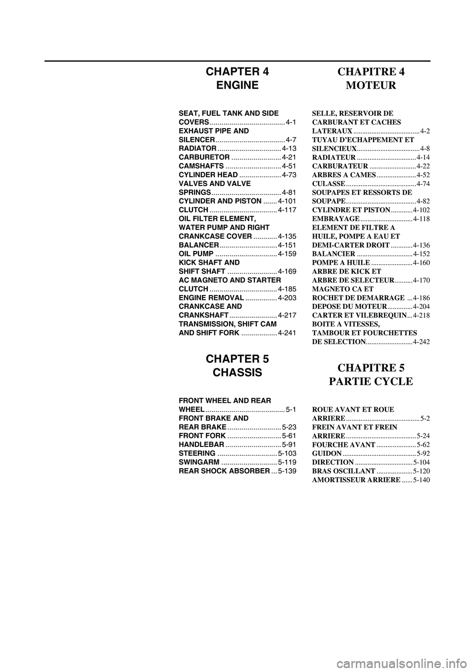
CHAPTER 4
ENGINE
SEAT, FUEL TANK AND SIDE
COVERS...................................... 4-1
EXHAUST PIPE AND
SILENCER................................... 4-7
RADIATOR................................ 4-13
CARBURETOR......................... 4-21
CAMSHAFTS............................ 4-51
CYLINDER HEAD..................... 4-73
VALVES AND VALVE
SPRINGS................................... 4-81
CYLINDER AND PISTON....... 4-101
CLUTCH.................................. 4-117
OIL FILTER ELEMENT,
WATER PUMP AND RIGHT
CRANKCASE COVER............ 4-135
BALANCER............................. 4-151
OIL PUMP............................... 4-159
KICK SHAFT AND
SHIFT SHAFT......................... 4-169
AC MAGNETO AND STARTER
CLUTCH.................................. 4-185
ENGINE REMOVAL................ 4-203
CRANKCASE AND
CRANKSHAFT........................ 4-217
TRANSMISSION, SHIFT CAM
AND SHIFT FORK.................. 4-241
CHAPTER 5
CHASSIS
FRONT WHEEL AND REAR
WHEEL........................................ 5-1
FRONT BRAKE AND
REAR BRAKE........................... 5-23
FRONT FORK........................... 5-61
HANDLEBAR............................ 5-91
STEERING.............................. 5-103
SWINGARM............................ 5-119
REAR SHOCK ABSORBER... 5-139
CHAPITRE 4
MOTEUR
SELLE, RESERVOIR DE
CARBURANT ET CACHES
LATERAUX..................................... 4-2
TUYAU D’ECHAPPEMENT ET
SILENCIEUX................................... 4-8
RADIATEUR................................. 4-14
CARBURATEUR.......................... 4-22
ARBRES A CAMES...................... 4-52
CULASSE....................................... 4-74
SOUPAPES ET RESSORTS DE
SOUPAPE....................................... 4-82
CYLINDRE ET PISTON............ 4-102
EMBRAYAGE............................. 4-118
ELEMENT DE FILTRE A
HUILE, POMPE A EAU ET
DEMI-CARTER DROIT............ 4-136
BALANCIER............................... 4-152
POMPE A HUILE....................... 4-160
ARBRE DE KICK ET
ARBRE DE SELECTEUR.......... 4-170
MAGNETO CA ET
ROCHET DE DEMARRAGE ... 4-186
DEPOSE DU MOTEUR.............. 4-204
CARTER ET VILEBREQUIN... 4-218
BOITE A VITESSES,
TAMBOUR ET FOURCHETTES
DE SELECTION.......................... 4-242
CHAPITRE 5
PARTIE CYCLE
ROUE AVANT ET ROUE
ARRIERE......................................... 5-2
FREIN AVANT ET FREIN
ARRIERE....................................... 5-24
FOURCHE AVANT...................... 5-62
GUIDON......................................... 5-92
DIRECTION................................ 5-104
BRAS OSCILLANT.................... 5-120
AMORTISSEUR ARRIERE...... 5-140
Page 24 of 860
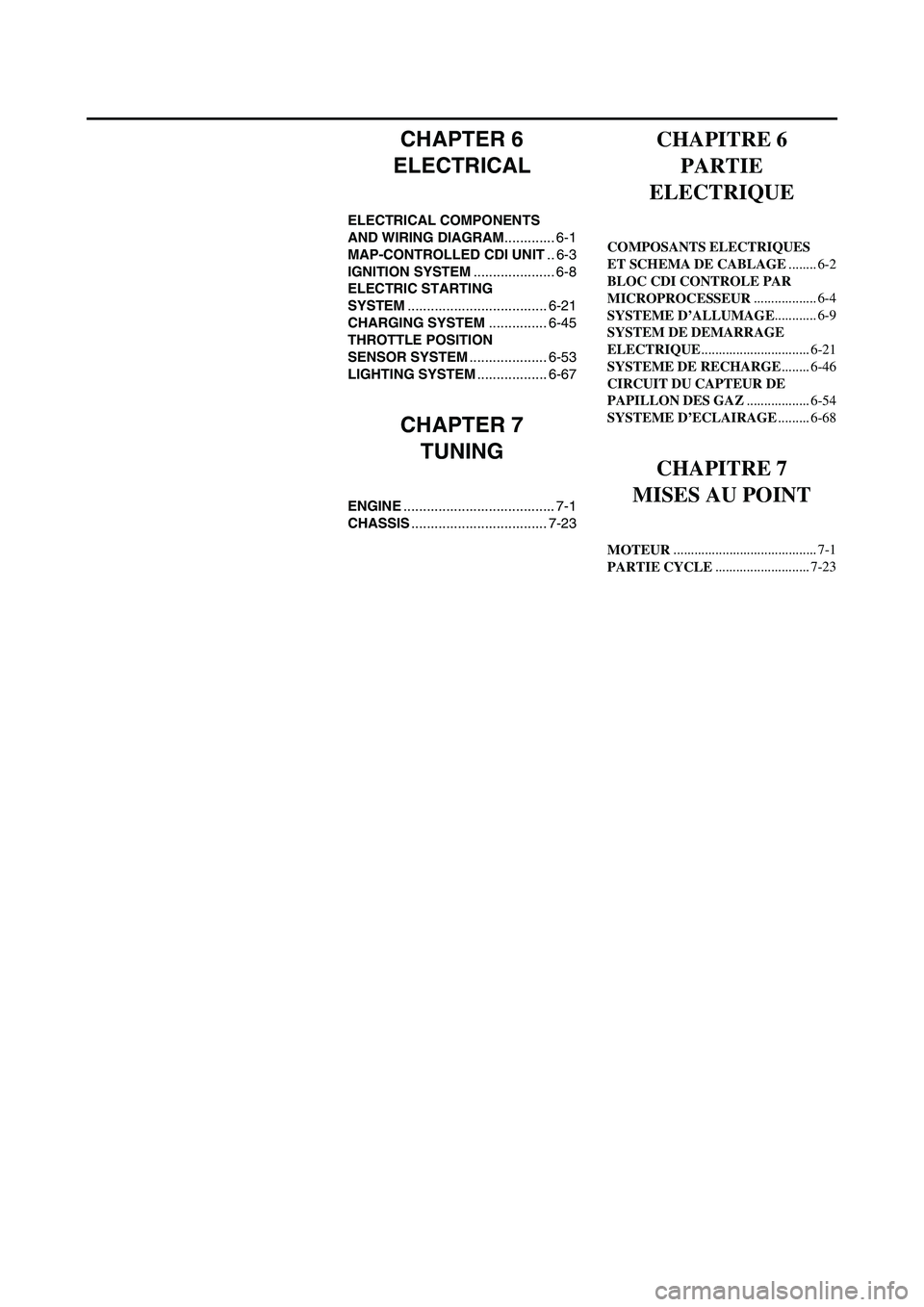
CHAPTER 6
ELECTRICAL
ELECTRICAL COMPONENTS
AND WIRING DIAGRAM............. 6-1
MAP-CONTROLLED CDI UNIT.. 6-3
IGNITION SYSTEM..................... 6-8
ELECTRIC STARTING
SYSTEM.................................... 6-21
CHARGING SYSTEM............... 6-45
THROTTLE POSITION
SENSOR SYSTEM.................... 6-53
LIGHTING SYSTEM.................. 6-67
CHAPTER 7
TUNING
ENGINE....................................... 7-1
CHASSIS................................... 7-23
CHAPITRE 6
PARTIE
ELECTRIQUE
COMPOSANTS ELECTRIQUES
ET SCHEMA DE CABLAGE........ 6-2
BLOC CDI CONTROLE PAR
MICROPROCESSEUR.................. 6-4
SYSTEME D’ALLUMAGE............ 6-9
SYSTEM DE DEMARRAGE
ELECTRIQUE............................... 6-21
SYSTEME DE RECHARGE........ 6-46
CIRCUIT DU CAPTEUR DE
PAPILLON DES GAZ.................. 6-54
SYSTEME D’ECLAIRAGE......... 6-68
CHAPITRE 7
MISES AU POINT
MOTEUR......................................... 7-1
PARTIE CYCLE........................... 7-23
Page 26 of 860
1 - 1
GEN
INFODESCRIPTION
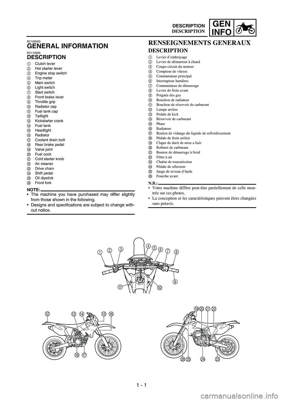
EC100000
GENERAL INFORMATION
EC110000
DESCRIPTION
1Clutch lever
2Hot starter lever
3Engine stop switch
4Trip meter
5Main switch
6Light switch
7Start switch
8Front brake lever
9Throttle grip
0Radiator cap
AFuel tank cap
BTaillight
CKickstarter crank
DFuel tank
EHeadlight
FRadiator
GCoolant drain bolt
HRear brake pedal
IValve joint
JFuel cock
KCold starter knob
LAir cleaner
MDrive chain
NShift pedal
OOil dipstick
PFront fork
NOTE:The machine you have purchased may differ slightly
from those shown in the following.
Designs and specifications are subject to change with-
out notice.
B
CDE
F
G H
1234
5
6
7
8
9
0 A
IJ
K
L
M N
O P
RENSEIGNEMENTS GENERAUX
DESCRIPTION
1Levier d’embrayage
2Levier de démarreur à chaud
3Coupe-circuit du moteur
4Compteur de vitesse
5Commutateur principal
6Interrupteur lumiêres
7Commutateur de démarrage
8Levier de frein avant
9Poignée des gaz
0Bouchon de radiateur
ABouchon de réservoir de carburant
BLampe arrière
CPedale de kick
DRéservoir de carburant
EPhare
FRadiateur
GBoulon de vidange du liquide de refroidissement
HPédale de frein arrière
IClapet de durit de mise a liair
JRobinet de carburant
KBouton de démarrage à froid
LFiltre à air
MChaîne de transmission
NPédale de sélecteur
OJauge de niveau d’huile
PFourche avant
N.B.:
Votre machine diffère peut-être partiellement de celle mon-
trée sur ces photos.
La conception et les caractéristiques peuvent êtres changées
sans préavis.
DESCRIPTION
Page 28 of 860

1 - 3
GEN
INFOMACHINE IDENTIFICATION
EC120001
MACHINE
IDENTIFICATION
There are two significant reasons for
knowing the serial number of your
machine:
1. When ordering parts, you can
give the number to your Yamaha
dealer for positive identification
of the model you own.
2. If your machine is stolen, the
authorities will need the number
to search for and identify your
machine.
EC121001VEHICLE IDENTIFICATION
NUMBER
The vehicle identification number
1
is stamped on the right of the steer-
ing head pipe.
1
EC123001ENGINE SERIAL NUMBER
The engine serial number
1 is
stamped into the elevated part of the
right-side of the engine.
1
EC124000MODEL LABEL
The model label
1 is affixed to the
frame under the rider’s seat. This
information will be needed to order
spare parts.1
IDENTIFICATION DE LA
MACHINE
Il ya deux bonnes raisons de connaître
les numéros de série de sa machine:
1. A la commande de pièces de
rechange, ces numéros permettent
au concessionnaire Yamaha d’iden-
tifier clairement la machine.
2. En cas de vol du véhicule, la police
réclamera ces numéros afin de faci-
liter son identification.
NUMERO D’IDENTIFICATION DU
VEHICULE
Le numéro d’identification du véhicule
1 est frappé du côté droit du tube de
direction.
NUMERO DE SERIE DU MOTEUR
Le numéro de série du moteur 1 est
estampé sur un bossage sur le côté droit
du moteur.
ETIQUETTE D’IDENTIFICATION
DU MODELE
L’étiquette d’identification du modèle 1
est apposée sur le cadre, sous la selle du
pilote. Les informations reprises sur
cette étiquette sont requises lors de la
commande de nouvelles pièces.
IDENTIFICATION DE LA MACHINE