engine coolant YAMAHA WR 250F 2004 User Guide
[x] Cancel search | Manufacturer: YAMAHA, Model Year: 2004, Model line: WR 250F, Model: YAMAHA WR 250F 2004Pages: 864, PDF Size: 22.07 MB
Page 344 of 864

4 - 19
ENGRADIATOR
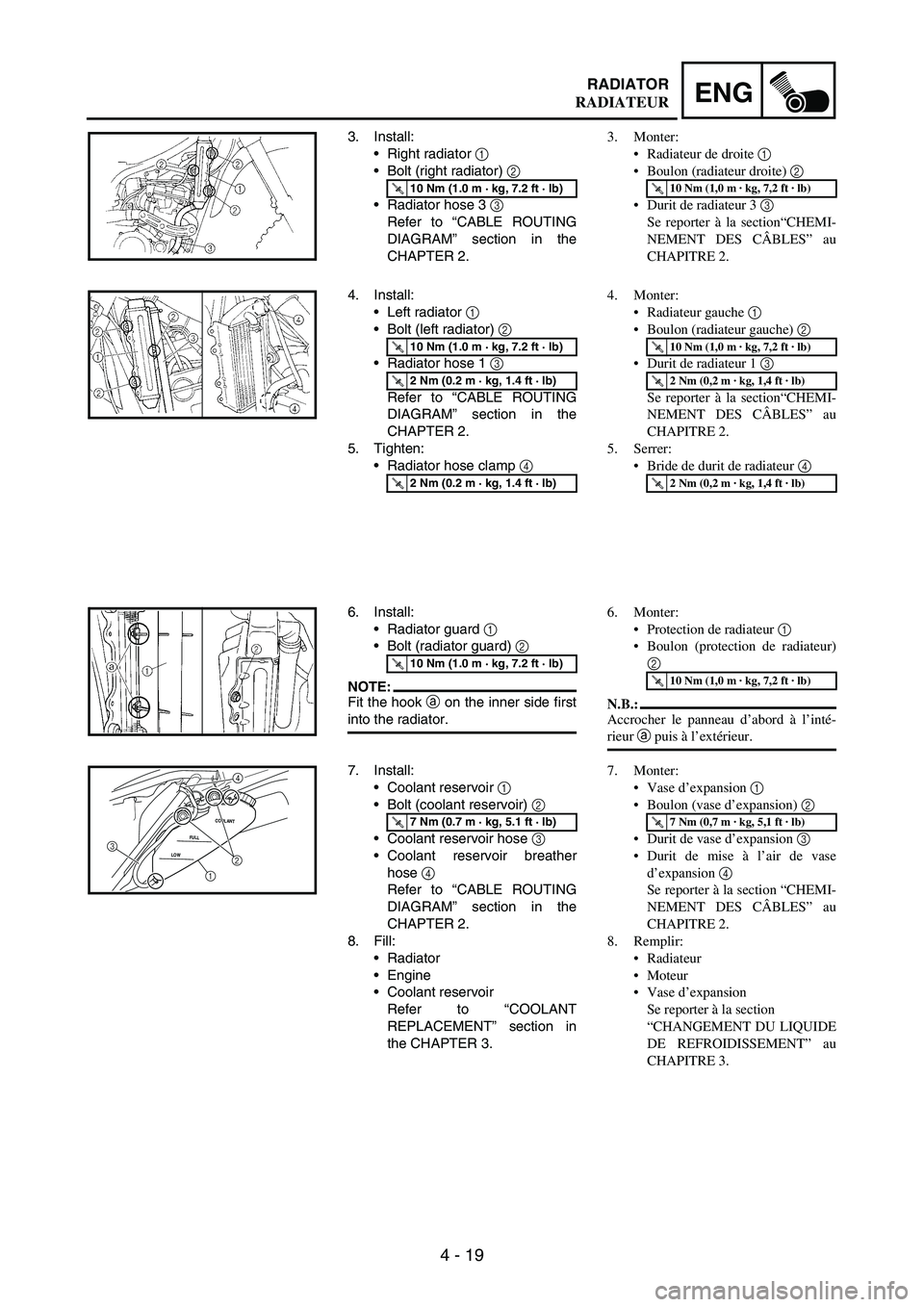
3. Install:
Right radiator
1
Bolt (right radiator)
2
Radiator hose 3
3
Refer to “CABLE ROUTING
DIAGRAM” section in the
CHAPTER 2.
T R..10 Nm (1.0 m · kg, 7.2 ft · lb)
4. Install:
Left radiator
1
Bolt (left radiator)
2
Radiator hose 1
3
Refer to “CABLE ROUTING
DIAGRAM” section in the
CHAPTER 2.
5. Tighten:
Radiator hose clamp
4
T R..10 Nm (1.0 m · kg, 7.2 ft · lb)
T R..2 Nm (0.2 m · kg, 1.4 ft · lb)
T R..2 Nm (0.2 m · kg, 1.4 ft · lb)
6. Install:
Radiator guard
1
Bolt (radiator guard)
2
NOTE:Fit the hook
a on the inner side first
into the radiator.
T R..10 Nm (1.0 m · kg, 7.2 ft · lb)
7. Install:
Coolant reservoir
1
Bolt (coolant reservoir)
2
Coolant reservoir hose
3
Coolant reservoir breather
hose
4
Refer to “CABLE ROUTING
DIAGRAM” section in the
CHAPTER 2.
8. Fill:
Radiator
Engine
Coolant reservoir
Refer to “COOLANT
REPLACEMENT” section in
the CHAPTER 3.
T R..7 Nm (0.7 m · kg, 5.1 ft · lb)
LOWFULLCOOLANT32
1
4
3. Monter:
Radiateur de droite 1
Boulon (radiateur droite) 2
Durit de radiateur 3 3
Se reporter à la section“CHEMI-
NEMENT DES CÂBLES” au
CHAPITRE 2.
T R..10 Nm (1,0 m · kg, 7,2 ft · lb)
4. Monter:
Radiateur gauche 1
Boulon (radiateur gauche) 2
Durit de radiateur 1 3
Se reporter à la section“CHEMI-
NEMENT DES CÂBLES” au
CHAPITRE 2.
5. Serrer:
Bride de durit de radiateur 4
T R..10 Nm (1,0 m · kg, 7,2 ft · lb)
T R..2 Nm (0,2 m · kg, 1,4 ft · lb)
T R..2 Nm (0,2 m · kg, 1,4 ft · lb)
6. Monter:
Protection de radiateur 1
Boulon (protection de radiateur)
2
N.B.:
Accrocher le panneau d’abord à l’inté-
rieur a puis à l’extérieur.
T R..10 Nm (1,0 m · kg, 7,2 ft · lb)
7. Monter:
Vase d’expansion 1
Boulon (vase d’expansion) 2
Durit de vase d’expansion 3
Durit de mise à l’air de vase
d’expansion 4
Se reporter à la section “CHEMI-
NEMENT DES CÂBLES” au
CHAPITRE 2.
8. Remplir:
Radiateur
Moteur
Vase d’expansion
Se reporter à la section
“CHANGEMENT DU LIQUIDE
DE REFROIDISSEMENT” au
CHAPITRE 3.
T R..7 Nm (0,7 m · kg, 5,1 ft · lb)
RADIATEUR
Page 460 of 864

4 - 135
ENGOIL FILTER ELEMENT, WATER PUMP AND RIGHT CRANKCASE COVER
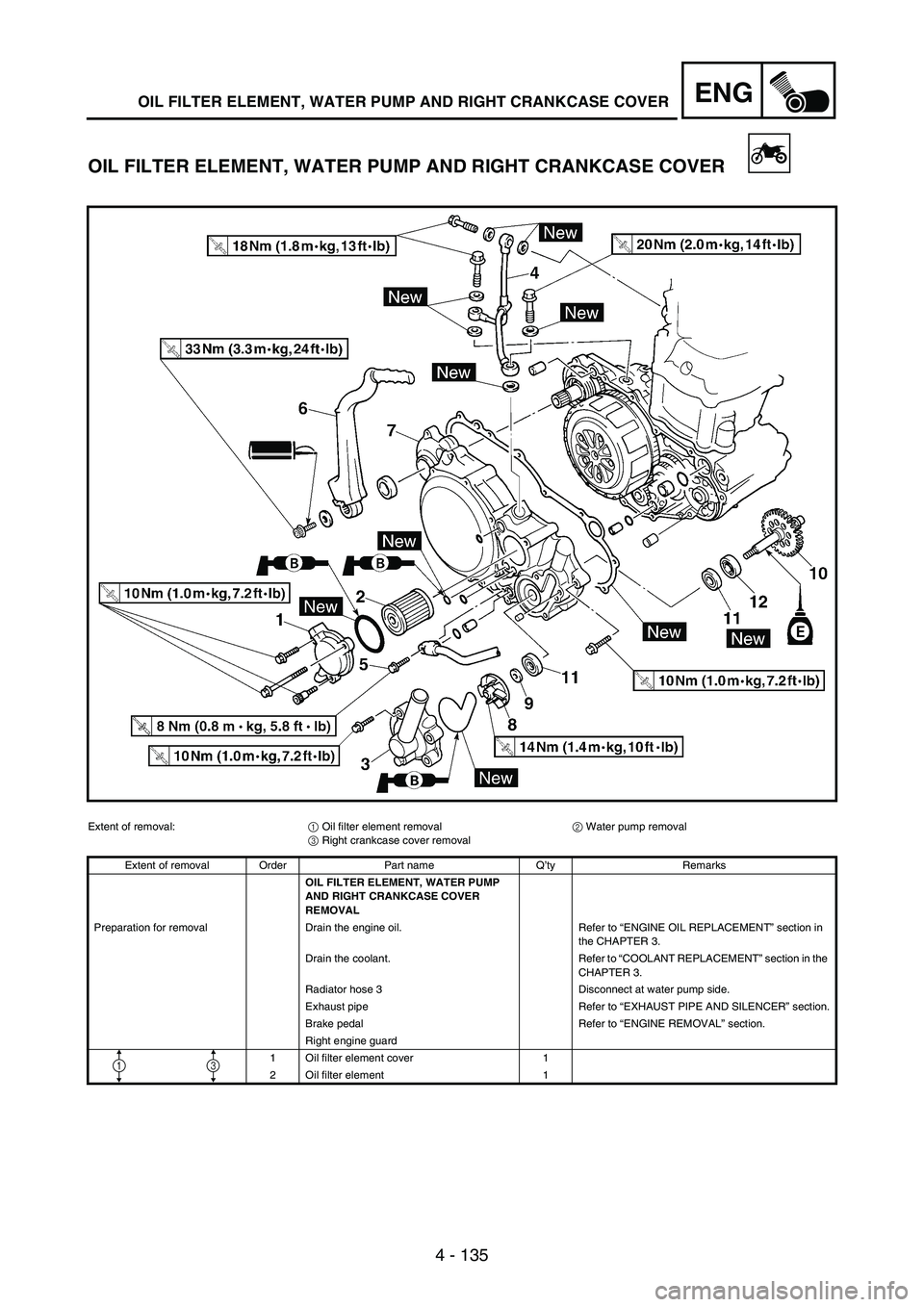
OIL FILTER ELEMENT, WATER PUMP AND RIGHT CRANKCASE COVER
Extent of removal:
1 Oil filter element removal
2 Water pump removal
3 Right crankcase cover removal
Extent of removal Order Part name Q’ty Remarks
OIL FILTER ELEMENT, WATER PUMP
AND RIGHT CRANKCASE COVER
REMOVAL
Preparation for removal Drain the engine oil. Refer to “ENGINE OIL REPLACEMENT” section in
the CHAPTER 3.
Drain the coolant. Refer to “COOLANT REPLACEMENT” section in the
CHAPTER 3.
Radiator hose 3 Disconnect at water pump side.
Exhaust pipe Refer to “EXHAUST PIPE AND SILENCER” section.
Brake pedal Refer to “ENGINE REMOVAL” section.
Right engine guard
1 Oil filter element cover 1
2 Oil filter element 1
13
Page 720 of 864

5 - 139
CHASREAR SHOCK ABSORBER
EC580000
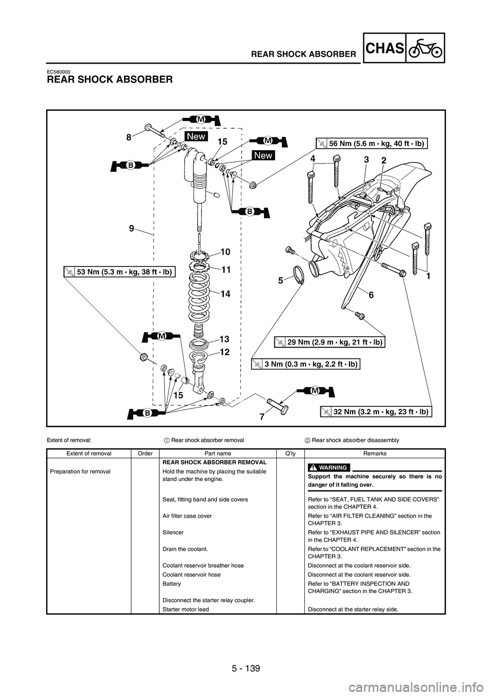
REAR SHOCK ABSORBER
Extent of removal:
1 Rear shock absorber removal
2 Rear shock absorber disassembly
Extent of removal Order Part name Q’ty Remarks
REAR SHOCK ABSORBER REMOVAL
WARNING
Support the machine securely so there is nodanger of it falling over. Preparation for removal Hold the machine by placing the suitable
stand under the engine.
Seat, fitting band and side covers Refer to “SEAT, FUEL TANK AND SIDE COVERS”
section in the CHAPTER 4.
Air filter case cover Refer to “AIR FILTER CLEANING” section in the
CHAPTER 3.
Silencer Refer to “EXHAUST PIPE AND SILENCER” section
in the CHAPTER 4.
Drain the coolant. Refer to “COOLANT REPLACEMENT” section in the
CHAPTER 3.
Coolant reservoir breather hose Disconnect at the coolant reservoir side.
Coolant reservoir hose Disconnect at the coolant reservoir side.
Battery Refer to “BATTERY INSPECTION AND
CHARGING” section in the CHAPTER 3.
Disconnect the starter relay coupler.
Starter motor lead Disconnect at the starter relay side.