fuel YAMAHA WR 250F 2004 User Guide
[x] Cancel search | Manufacturer: YAMAHA, Model Year: 2004, Model line: WR 250F, Model: YAMAHA WR 250F 2004Pages: 864, PDF Size: 22.07 MB
Page 64 of 864
1 - 39
GEN
INFO
1. Inspect the coolant level.
2. Turn the fuel cock to “ON”.
3. Push on the main switch to “ON”.
4. Shift the transmission into neu-
tral.
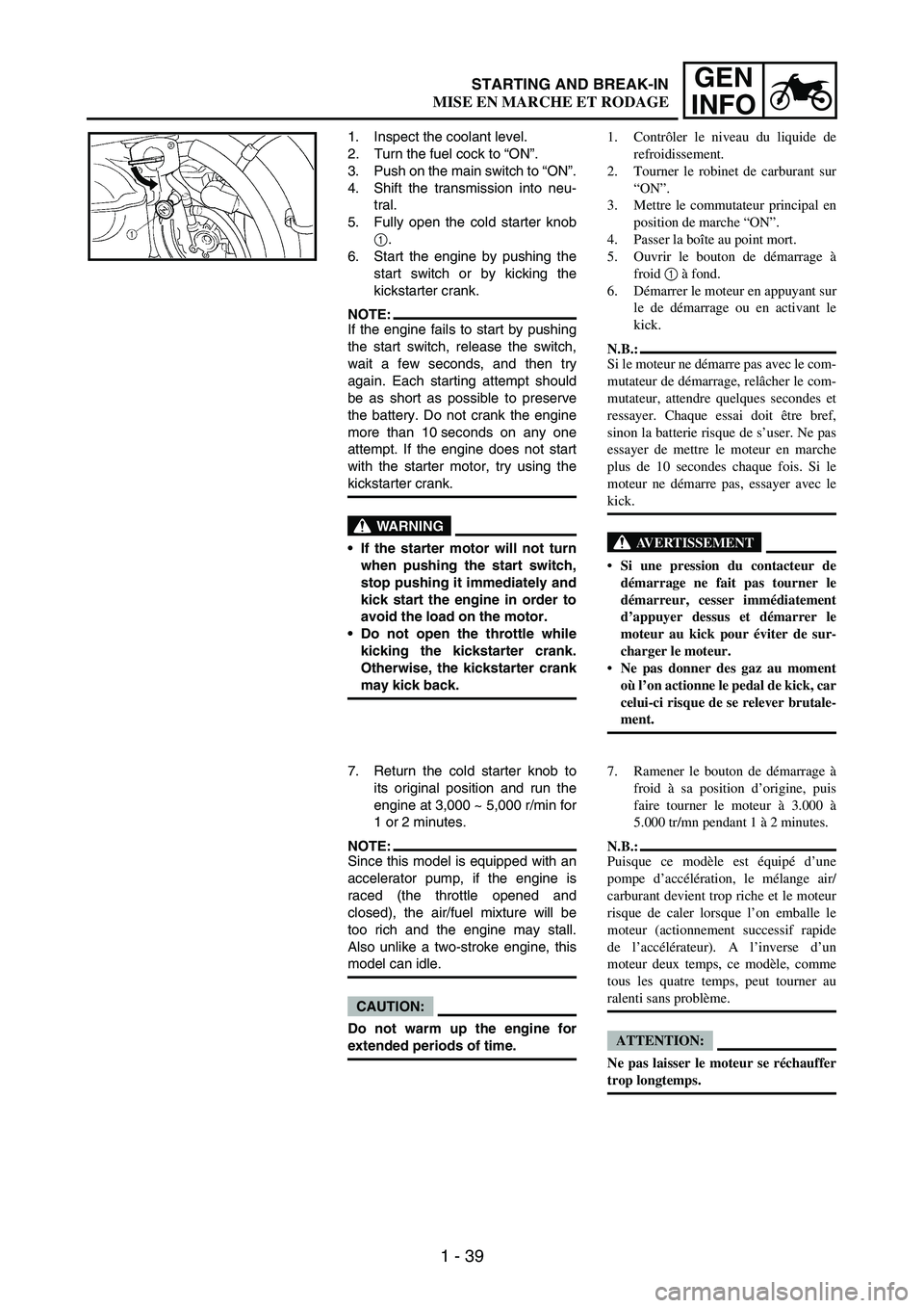
5. Fully open the cold starter knob
1.
6. Start the engine by pushing the
start switch or by kicking the
kickstarter crank.
NOTE:If the engine fails to start by pushing
the start switch, release the switch,
wait a few seconds, and then try
again. Each starting attempt should
be as short as possible to preserve
the battery. Do not crank the engine
more than 10 seconds on any one
attempt. If the engine does not start
with the starter motor, try using the
kickstarter crank.
WARNING
If the starter motor will not turn
when pushing the start switch,
stop pushing it immediately and
kick start the engine in order to
avoid the load on the motor.
Do not open the throttle while
kicking the kickstarter crank.
Otherwise, the kickstarter crank
may kick back.
7. Return the cold starter knob to
its original position and run the
engine at 3,000 ~ 5,000 r/min for
1 or 2 minutes.
NOTE:Since this model is equipped with an
accelerator pump, if the engine is
raced (the throttle opened and
closed), the air/fuel mixture will be
too rich and the engine may stall.
Also unlike a two-stroke engine, this
model can idle.
CAUTION:
Do not warm up the engine for
extended periods of time.1. Contrôler le niveau du liquide de
refroidissement.
2. Tourner le robinet de carburant sur
“ON”.
3. Mettre le commutateur principal en
position de marche “ON”.
4. Passer la boîte au point mort.
5. Ouvrir le bouton de démarrage à
froid 1 à fond.
6. Démarrer le moteur en appuyant sur
le de démarrage ou en activant le
kick.
N.B.:
Si le moteur ne démarre pas avec le com-
mutateur de démarrage, relâcher le com-
mutateur, attendre quelques secondes et
ressayer. Chaque essai doit être bref,
sinon la batterie risque de s’user. Ne pas
essayer de mettre le moteur en marche
plus de 10 secondes chaque fois. Si le
moteur ne démarre pas, essayer avec le
kick.
AVERTISSEMENT
Si une pression du contacteur de
démarrage ne fait pas tourner le
démarreur, cesser immédiatement
d’appuyer dessus et démarrer le
moteur au kick pour éviter de sur-
charger le moteur.
Ne pas donner des gaz au moment
où l’on actionne le pedal de kick, car
celui-ci risque de se relever brutale-
ment.
7. Ramener le bouton de démarrage à
froid à sa position d’origine, puis
faire tourner le moteur à 3.000 à
5.000 tr/mn pendant 1 à 2 minutes.
N.B.:
Puisque ce modèle est équipé d’une
pompe d’accélération, le mélange air/
carburant devient trop riche et le moteur
risque de caler lorsque l’on emballe le
moteur (actionnement successif rapide
de l’accélérateur). A l’inverse d’un
moteur deux temps, ce modèle, comme
tous les quatre temps, peut tourner au
ralenti sans problème.
ATTENTION:
Ne pas laisser le moteur se réchauffer
trop longtemps.
STARTING AND BREAK-IN
MISE EN MARCHE ET RODAGE
Page 68 of 864
1 - 43
GEN
INFO
BREAK-IN PROCEDURES
1. Before starting the engine, fill the
fuel tank with the fuel.
2. Perform the pre-operation
checks on the machine.
3. Start and warm up the engine.
Check the idle speed, and check
the operation of the controls and
the engine stop switch. Then,
restart the engine and check its
operation within no more than 5
minutes after it is restarted.
4. Operate the machine in the
lower gears at moderate throttle
openings for five to eight min-
utes.
5. Check how the engine runs
when the machine is ridden with
the throttle 1/4 to 1/2 open (low
to medium speed) for about one
hour.
6. Restart the engine and check
the operation of the machine
throughout its entire operating
range. Restart the machine and
operate it for about 10 to 15
more minutes. The machine will
now be ready to race.
CAUTION:
After the break-in or before each
race, you must check the entire
machine for loose fittings and
fasteners as per “TORQUE-
CHECK POINTS”.
Tighten all such fasteners as
required.
When any of the following parts
have been replaced, they must
be broken in.
CYLINDER AND CRANKSHAFT:
About one hour of break-in
operation is necessary.
PISTON, RING, VALVES, CAM-
SHAFTS AND GEARS:
These parts require about 30
minutes of break-in operation at
half-throttle or less. Observe the
condition of the engine carefully
during operation.PROCEDURE DE RODAGE
1. Avant de mettre le moteur en mar-
che, faire le plein d’essence.
2. Effectuer les contrôles avant utilisa-
tion de la machine.
3. Lancer le moteur et le laisser se
réchauffer. Vérifier le régime de
ralenti, le fonctionnement des com-
mandes et l’efficacité du coupe-cir-
cuit. Remettre ensuite le moteur en
marche et vérifier son fonctionne-
ment dans les 5 minutes maximum.
4. Piloter la machine sur les rapports
inférieurs et à régime modéré durant
les cinq à huit premières minutes.
5. Vérifier le fonctionnement du
moteur en roulant pendant environ 1
heure à une ouverture des gaz de 1/4
à 1/2 (petite à moyenne vitesse) .
6. Remettre le moteur en marche et
vérifier son fonctionnement à tous
les régimes. Relancer le moteur et
piloter la machine pendant 10 à 15
minutes supplémentaires. Elle sera
alors prête pour la course.
ATTENTION:
Après le rodage ou avant chaque
course, il faut vérifier toutes les fixa-
tions et serrages comme indiqué
dans “POINTS DE VERIFICA-
TION DE COUPLE DE SER-
RAGE”.
Serrer toutes ces fixations comme
requis.
Après avoir remplacé les pièces sui-
vantes, un nouveau rodage est
nécessaire.
CYLINDRE ET VILEBREQUIN:
Une heure environ de rodage est
nécessaire.
PISTONS, SEGMENTS, SOUPAPES,
ARBRES A CAMES ET PIGNONS:
Ces pièces nécessitent un rodage de
30 minutes environ à une ouverture
des gaz de maximum 1/2. Surveiller
attentivement l’état du moteur pen-
dant la marche.
STARTING AND BREAK-IN
MISE EN MARCHE ET RODAGE
Page 70 of 864
1 - 45
GEN
INFO
TORQUE-CHECK POINTS
Frame construction Frame to rear frame
Combined seat and fuel tank Fuel tank to frame
Exhaust system Silencer to rear frame
Engine mounting Frame to engine
Engine bracket to engine
Engine bracket to frame
Steering Steering stem to handlebar Steering stem to frame
Steering stem to upper bracket
Upper bracket to handlebar
Suspension Front Steering stem to front fork Front fork to upper bracket
Front fork to lower bracket
Rear For link type Assembly of links
Link to frame
Link to rear shock absorber
Link to swingarm
Rear Installation of rear
shock absorberRear shock absorber to frame
Rear Installation of swingarm Tightening of pivot shaft
Wheel Installation of wheel Front Tightening of wheel axle
Tightening of axle holder
Rear Tightening of wheel axle
Wheel to rear wheel sprocket
Brake Front Brake caliper to front fork
Brake disc to wheel
Tightening of union bolt
Brake master cylinder to handlebar
Tightening of bleed screw
Rear Brake pedal to frame
Brake disc to wheel
Tightening of union bolt
Brake master cylinder to frame
Tightening of bleed screw
Fuel system Fuel tank to fuel cock
Lubrication system Tightening of oil hose clamp
NOTE:Concerning the tightening torque, refer to
“MAINTENANCE SPECIFICATIONS” sec-
tion in the CHAPTER 2.
TORQUE-CHECK POINTS
Page 78 of 864
1 - 53
GEN
INFO
EC1B2001STORAGE
If your machine is to be stored for 60
days or more, some preventive mea-
sures must be taken to avoid deterio-
ration. After cleaning the machine
thoroughly, prepare it for storage as
follows:
1. Drain the fuel tank, fuel lines,
and the carburetor float bowl.
2. Remove the spark plug, pour a
tablespoon of SAE 10W-30
motor oil in the spark plug hole,
and reinstall the plug. With the
engine stop switch pushed in,
kick the engine over several
times to coat the cylinder walls
with oil.
3. Remove the drive chain, clean it
thoroughly with solvent, and
lubricate it. Reinstall the chain or
store it in a plastic bag tied to the
frame.
4. Lubricate all control cables.
5. Block the frame up to raise the
wheels off the ground.
6. Tie a plastic bag over the
exhaust pipe outlet to prevent
moisture from entering.
7. If the machine is to be stored in a
humid or salt-air environment,
coat all exposed metal surfaces
with a film of light oil. Do not
apply oil to rubber parts or the
seat cover.
NOTE:Make any necessary repairs before
the machine is stored.RANGEMENT
Si l’on remise la machine pour 60 jours
ou plus, il faut prendre des mesures de
conservation pour éviter sa détérioration.
Après un nettoyage soigné, préparer la
machine de la manière suivante:
1. Vider le réservoir, les conduites
d’essence et la cuve du carburateur.
2. Déposer la bougie, verser une
cuillère à soupe d’huile moteur SAE
10W-30 dans le trou de bougie, et la
remettre en place. Coupe-circuit à la
position arrêt, donner plusieurs
coups de kick pour enduire le cylin-
dre d’huile.
3. Déposer la chaîne, la nettoyer soi-
gneusement au dissolvant et lubri-
fier. Remonter la chaîne ou la
ranger dans un sachet plastique
fermé fixé au cadre.
4. Lubrifier tous les câbles de com-
mande.
5. Mettre le cadre sur plots pour soule-
ver les roues du sol.
6. Fixer un sachet plastique sur la sor-
tie du pot d’échappement pour évi-
ter l’introduction d’humidité.
7. Si la machine est placée dans une
atmosphère humide ou marine,
enduire toutes les surfaces métalli-
ques nues d’une fine couche
d’huile. Ne pas appliquer d’huile
sur les parties en caoutchouc ou sur
la selle.
N.B.:
Avant de ranger la machine, effectuer
toutes les réparations nécessaires.
CLEANING AND STORAGE
NETTOYAGE ET RANGEMENT
Page 80 of 864
GENERAL SPECIFICATIONS
2 - 1
SPEC
EC200000
SPECIFICATIONS
EC211000
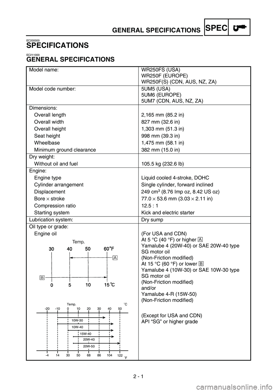
GENERAL SPECIFICATIONS
Model name: WR250FS (USA)
WR250F (EUROPE)
WR250F(S) (CDN, AUS, NZ, ZA)
Model code number: 5UM5 (USA)
5UM6 (EUROPE)
5UM7 (CDN, AUS, NZ, ZA)
Dimensions:
Overall length 2,165 mm (85.2 in)
Overall width 827 mm (32.6 in)
Overall height 1,303 mm (51.3 in)
Seat height 998 mm (39.3 in)
Wheelbase 1,475 mm (58.1 in)
Minimum ground clearance 382 mm (15.0 in)
Dry weight:
Without oil and fuel 105.5 kg (232.6 lb)
Engine:
Engine type Liquid cooled 4-stroke, DOHC
Cylinder arrangement Single cylinder, forward inclined
Displacement 249 cm
3 (8.76 Imp oz, 8.42 US oz)
Bore × stroke 77.0 × 53.6 mm (3.03 × 2.11 in)
Compression ratio 12.5 : 1
Starting system Kick and electric starter
Lubrication system: Dry sump
Oil type or grade:
Engine oil (For USA and CDN)
At 5 °C (40 °F) or higher È
Yamalube 4 (20W-40) or SAE 20W-40 type
SG motor oil
(Non-Friction modified)
At 15 °C (60 °F) or lower É
Yamalube 4 (10W-30) or SAE 10W-30 type
SG motor oil
(Non-Friction modified)
and/or
Yamalube 4-R (15W-50)
(Non-Friction modified)
(Except for USA and CDN)
API “SG” or higher grade
-20
-4-10
140
3010
5020
6830
8640 50
104
122˚CTemp.
˚F
10W-30
10W-40
20W-40
20W-50
15W-40
2
Page 81 of 864
GENERAL SPECIFICATIONS
2 - 2
SPEC
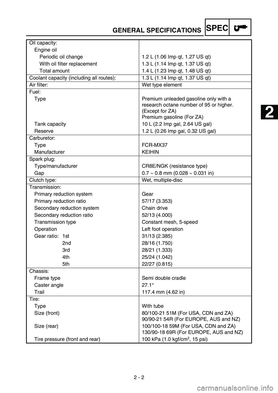
Oil capacity:
Engine oil
Periodic oil change 1.2 L (1.06 Imp qt, 1.27 US qt)
With oil filter replacement 1.3 L (1.14 Imp qt, 1.37 US qt)
Total amount 1.4 L (1.23 Imp qt, 1.48 US qt)
Coolant capacity (including all routes): 1.3 L (1.14 Imp qt, 1.37 US qt)
Air filter: Wet type element
Fuel:
Type Premium unleaded gasoline only with a
research octane number of 95 or higher.
(Except for ZA)
Premium gasoline (For ZA)
Tank capacity 10 L (2.2 Imp gal, 2.64 US gal)
Reserve 1.2 L (0.26 Imp gal, 0.32 US gal)
Carburetor:
Type FCR-MX37
Manufacturer KEIHIN
Spark plug:
Type/manufacturer CR8E/NGK (resistance type)
Gap 0.7 ~ 0.8 mm (0.028 ~ 0.031 in)
Clutch type: Wet, multiple-disc
Transmission:
Primary reduction system Gear
Primary reduction ratio 57/17 (3.353)
Secondary reduction system Chain drive
Secondary reduction ratio 52/13 (4.000)
Transmission type Constant mesh, 5-speed
Operation Left foot operation
Gear ratio: 1st 31/13 (2.385)
2nd 28/16 (1.750)
3rd 28/21 (1.333)
4th 25/24 (1.042)
5th 22/27 (0.815)
Chassis:
Frame type Semi double cradle
Caster angle 27.1°
Trail 117.4 mm (4.62 in)
Tire:
Type With tube
Size (front) 80/100-21 51M (For USA, CDN and ZA)
90/90-21 54R (For EUROPE, AUS and NZ)
Size (rear) 100/100-18 59M (For USA, CDN and ZA)
130/90-18 69R (For EUROPE, AUS and NZ)
Tire pressure (front and rear) 100 kPa (1.0 kgf/cm
2, 15 psi)
1
2
3
4
5
6
7
Page 94 of 864
MAINTENANCE SPECIFICATIONS
2 - 15
SPEC
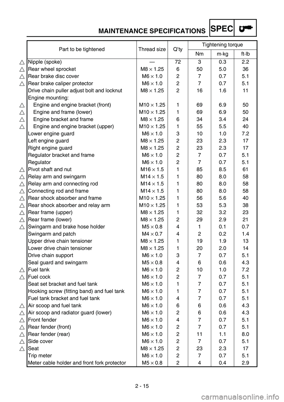
Part to be tightened Thread size Q’tyTightening torque
Nm m·kg ft·lb
Nipple (spoke)—72 3 0.3 2.2
Rear wheel sprocket M8 × 1.25 6 50 5.0 36
Rear brake disc cover M6 × 1.0 2 7 0.7 5.1
Rear brake caliper protector M6 × 1.0 2 7 0.7 5.1
Drive chain puller adjust bolt and locknut M8 × 1.25 2 16 1.6 11
Engine mounting:
Engine and engine bracket (front) M10 × 1.25 1 69 6.9 50
Engine and frame (lower) M10 × 1.25 1 69 6.9 50
Engine bracket and frame M8 × 1.25 6 34 3.4 24
Engine and engine bracket (upper) M10 × 1.25 1 55 5.5 40
Lower engine guard M6 × 1.0 3 10 1.0 7.2
Left engine guard M8 × 1.25 2 23 2.3 17
Right engine guard M8 × 1.25 2 23 2.3 17
Regulator bracket and frame M6 × 1.0 2 7 0.7 5.1
Regulator M6 × 1.0 2 7 0.7 5.1
Pivot shaft and nut M16 × 1.5 1 85 8.5 61
Relay arm and swingarm M14 × 1.5 1 80 8.0 58
Relay arm and connecting rod M14 × 1.5 1 80 8.0 58
Connecting rod and frame M14 × 1.5 1 80 8.0 58
Rear shock absorber and frame M10 × 1.25 1 56 5.6 40
Rear shock absorber and relay arm M10 × 1.25 1 53 5.3 38
Rear frame (upper) M8 × 1.25 1 32 3.2 23
Rear frame (lower) M8 × 1.25 2 29 2.9 21
Swingarm and brake hose holder M5 × 0.8 4 1 0.1 0.7
Swingarm and patch M4 × 0.7 4 2 0.2 1.4
Upper drive chain tensioner M8 × 1.25 1 19 1.9 13
Lower drive chain tensioner M8 × 1.25 1 20 2.0 14
Drive chain support M6 × 1.0 3 7 0.7 5.1
Seal guard and swingarm M5 × 0.8 4 6 0.6 4.3
Fuel tank M6 × 1.0 2 10 1.0 7.2
Fuel cock M6 × 1.0 2 7 0.7 5.1
Seat set bracket and fuel tank M6 × 1.0 1 7 0.7 5.1
Hooking screw (fitting band) and fuel tank M6 × 1.0 1 7 0.7 5.1
Fuel tank bracket and fuel tank M6 × 1.0 4 7 0.7 5.1
Air scoop and fuel tank M6 × 1.0 6 6 0.6 4.3
Air scoop and radiator guard (lower) M6 × 1.0 2 6 0.6 4.3
Front fender M6 × 1.0 4 7 0.7 5.1
Rear fender (front) M6 × 1.0 2 7 0.7 5.1
Rear fender (rear) M6 × 1.0 2 11 1.1 8.0
Side cover M6 × 1.0 2 7 0.7 5.1
Seat M8 × 1.25 2 23 2.3 17
Trip meter M6 × 1.0 2 7 0.7 5.1
Meter cable holder and front fork protector M5 × 0.8 2 4 0.4 2.9
Page 176 of 864
SPEC
2 - 97
CABLE ROUTING DIAGRAM
EC240000
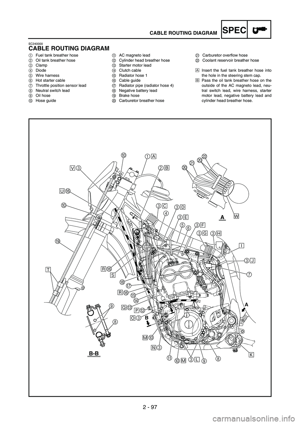
CABLE ROUTING DIAGRAM
1Fuel tank breather hose
2Oil tank breather hose
3Clamp
4Diode
5Wire harness
6Hot starter cable
7Throttle position sensor lead
8Neutral switch lead
9Oil hose
0Hose guideAAC magneto lead
BCylinder head breather hose
CStarter motor lead
DClutch cable
ERadiator hose 1
FCable guide
GRadiator pipe (radiator hose 4)
HNegative battery lead
IBrake hose
JCarburetor breather hoseKCarburetor overflow hose
LCoolant reservoir breather hose
ÈInsert the fuel tank breather hose into
the hole in the steering stem cap.
ÉPass the oil tank breather hose on the
outside of the AC magneto lead, neu-
tral switch lead, wire harness, starter
motor lead, negative battery lead and
cylinder head breather hose.
A
A
B-B
B
B
Þ 3
4
3
5
63
3
3
3
7 J
JKL
8
9 3
0 A 3 0 3B CD E FG H F
9
8 I0F30
1
2 È
É
Ê
Ì
Î Í
3
Ë
Ï
Ð
Ñ
Ò
Ó
Ô Õ Ö× Ø Ù
Ú Û
Ô Ù ÜÝ
Page 193 of 864
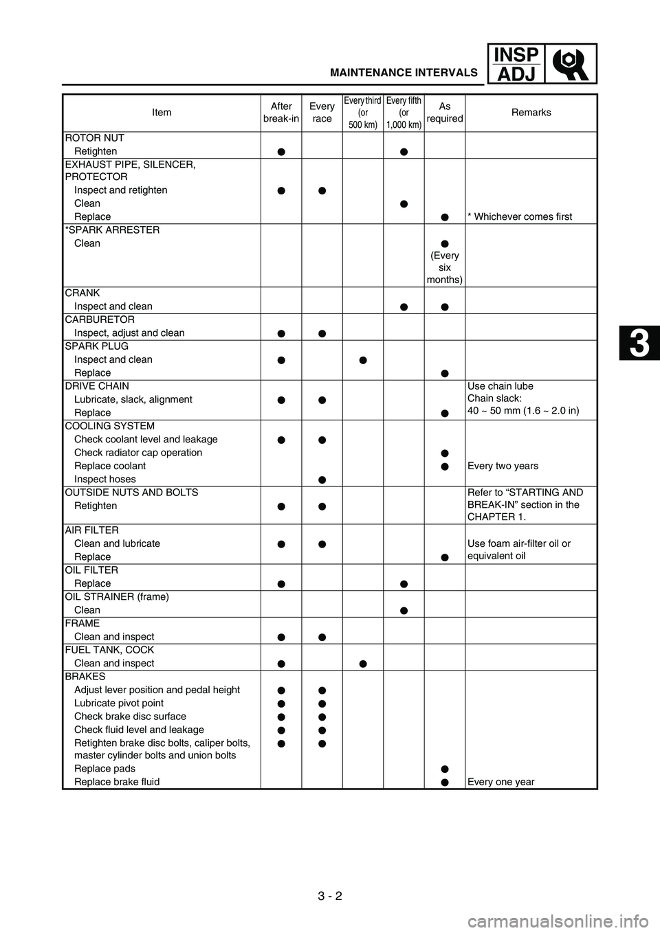
3 - 2
INSP
ADJ
MAINTENANCE INTERVALS
ROTOR NUT
Retighten
EXHAUST PIPE, SILENCER,
PROTECTOR
Inspect and retighten
Clean
Replace* Whichever comes first
*SPARK ARRESTER
Clean
(Every
six
months)
CRANK
Inspect and clean
CARBURETOR
Inspect, adjust and clean
SPARK PLUG
Inspect and clean
Replace
DRIVE CHAINUse chain lube
Chain slack:
40 ~ 50 mm (1.6 ~ 2.0 in) Lubricate, slack, alignment
Replace
COOLING SYSTEM
Check coolant level and leakage
Check radiator cap operation
Replace coolantEvery two years
Inspect hoses
OUTSIDE NUTS AND BOLTS Refer to “STARTING AND
BREAK-IN” section in the
CHAPTER 1. Retighten
AIR FILTER
Clean and lubricate Use foam air-filter oil or
equivalent oil
Replace
OIL FILTER
Replace
OIL STRAINER (frame)
Clean
FRAME
Clean and inspect
FUEL TANK, COCK
Clean and inspect
BRAKES
Adjust lever position and pedal height
Lubricate pivot point
Check brake disc surface
Check fluid level and leakage
Retighten brake disc bolts, caliper bolts,
master cylinder bolts and union bolts
Replace pads
Replace brake fluid Every one yearItemAfter
break-inEvery
race
Every third
(or
500 km)Every fifth
(or
1,000 km)As
requiredRemarks
1
2
3
4
5
6
7
Page 207 of 864
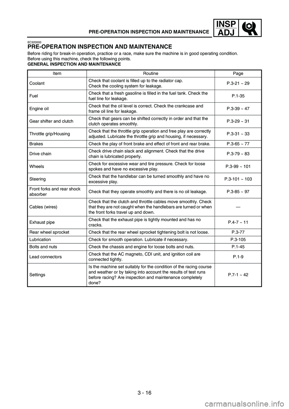
3 - 16
INSP
ADJ
PRE-OPERATION INSPECTION AND MAINTENANCE
EC320000
PRE-OPERATION INSPECTION AND MAINTENANCE
Before riding for break-in operation, practice or a race, make sure the machine is in good operating condition.
Before using this machine, check the following points.
GENERAL INSPECTION AND MAINTENANCE
Item Routine Page
CoolantCheck that coolant is filled up to the radiator cap.
Check the cooling system for leakage.P.3-21 ~ 29
FuelCheck that a fresh gasoline is filled in the fuel tank. Check the
fuel line for leakage.P.1-35
Engine oilCheck that the oil level is correct. Check the crankcase and
frame oil line for leakage.P.3-39 ~ 47
Gear shifter and clutchCheck that gears can be shifted correctly in order and that the
clutch operates smoothly.P.3-29 ~ 31
Throttle grip/HousingCheck that the throttle grip operation and free play are correctly
adjusted. Lubricate the throttle grip and housing, if necessary.P.3-31 ~ 33
Brakes Check the play of front brake and effect of front and rear brake. P.3-65 ~ 77
Drive chainCheck drive chain slack and alignment. Check that the drive
chain is lubricated properly.P.3-79 ~ 83
WheelsCheck for excessive wear and tire pressure. Check for loose
spokes and have no excessive play.P.3-99 ~ 101
SteeringCheck that the handlebar can be turned smoothly and have no
excessive play.P.3-101 ~ 103
Front forks and rear shock
absorberCheck that they operate smoothly and there is no oil leakage. P.3-85 ~ 97
Cables (wires)Check that the clutch and throttle cables move smoothly. Check
that they are not caught when the handlebars are turned or when
the front forks travel up and down.—
Exhaust pipeCheck that the exhaust pipe is tightly mounted and has no
cracks.P.4-7 ~ 11
Rear wheel sprocket Check that the rear wheel sprocket tightening bolt is not loose. P.3-77
Lubrication Check for smooth operation. Lubricate if necessary. P.3-105
Bolts and nuts Check the chassis and engine for loose bolts and nuts. P.1-45
Lead connectorsCheck that the AC magneto, CDI unit, and ignition coil are
connected tightly.P.1-9
SettingsIs the machine set suitably for the condition of the racing course
and weather or by taking into account the results of test runs
before racing? Are inspection and maintenance completely
done?P.7-1 ~ 42