relay YAMAHA WR 250F 2005 Notices Demploi (in French)
[x] Cancel search | Manufacturer: YAMAHA, Model Year: 2005, Model line: WR 250F, Model: YAMAHA WR 250F 2005Pages: 864, PDF Size: 18.1 MB
Page 94 of 864

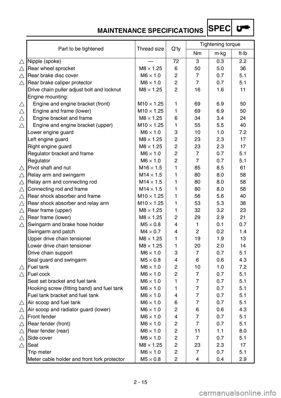
MAINTENANCE SPECIFICATIONS
2 - 15
SPEC
Part to be tightened Thread size Q’tyTightening torque
Nm m·kg ft·lb
Nipple (spoke)—72 3 0.3 2.2
Rear wheel sprocket M8 × 1.25 6 50 5.0 36
Rear brake disc cover M6 × 1.0 2 7 0.7 5.1
Rear brake caliper protector M6 × 1.0 2 7 0.7 5.1
Drive chain puller adjust bolt and locknut M8 × 1.25 2 16 1.6 11
Engine mounting:
Engine and engine bracket (front) M10 × 1.25 1 69 6.9 50
Engine and frame (lower) M10 × 1.25 1 69 6.9 50
Engine bracket and frame M8 × 1.25 6 34 3.4 24
Engine and engine bracket (upper) M10 × 1.25 1 55 5.5 40
Lower engine guard M6 × 1.0 3 10 1.0 7.2
Left engine guard M8 × 1.25 2 23 2.3 17
Right engine guard M8 × 1.25 2 23 2.3 17
Regulator bracket and frame M6 × 1.0 2 7 0.7 5.1
Regulator M6 × 1.0 2 7 0.7 5.1
Pivot shaft and nut M16 × 1.5 1 85 8.5 61
Relay arm and swingarm M14 × 1.5 1 80 8.0 58
Relay arm and connecting rod M14 × 1.5 1 80 8.0 58
Connecting rod and frame M14 × 1.5 1 80 8.0 58
Rear shock absorber and frame M10 × 1.25 1 56 5.6 40
Rear shock absorber and relay arm M10 × 1.25 1 53 5.3 38
Rear frame (upper) M8 × 1.25 1 32 3.2 23
Rear frame (lower) M8 × 1.25 2 29 2.9 21
Swingarm and brake hose holder M5 × 0.8 4 1 0.1 0.7
Swingarm and patch M4 × 0.7 4 2 0.2 1.4
Upper drive chain tensioner M8 × 1.25 1 19 1.9 13
Lower drive chain tensioner M8 × 1.25 1 20 2.0 14
Drive chain support M6 × 1.0 3 7 0.7 5.1
Seal guard and swingarm M5 × 0.8 4 6 0.6 4.3
Fuel tank M6 × 1.0 2 10 1.0 7.2
Fuel cock M6 × 1.0 2 7 0.7 5.1
Seat set bracket and fuel tank M6 × 1.0 1 7 0.7 5.1
Hooking screw (fitting band) and fuel tank M6 × 1.0 1 7 0.7 5.1
Fuel tank bracket and fuel tank M6 × 1.0 4 7 0.7 5.1
Air scoop and fuel tank M6 × 1.0 6 7 0.7 5.1
Air scoop and radiator guard (lower) M6 × 1.0 2 6 0.6 4.3
Front fender M6 × 1.0 4 7 0.7 5.1
Rear fender (front) M6 × 1.0 2 7 0.7 5.1
Rear fender (rear) M6 × 1.0 2 11 1.1 8.0
Side cover M6 × 1.0 2 7 0.7 5.1
Seat M8 × 1.25 2 23 2.3 17
Trip meter M6 × 1.0 2 7 0.7 5.1
Meter cable holder and front fork protector M5 × 0.8 2 4 0.4 2.9
Page 97 of 864

MAINTENANCE SPECIFICATIONS
2 - 18
SPEC
NOTE:
Tighten the rotor nut to 65 Nm (6.5 m kg, 47 ft lb), loosen and retighten the rotor nut to 65 Nm
(6.5 m kg, 47 ft lb). Starter relay:
Model/manufacturer 2768090-A/JIDECO ----
Amperage rating 180 A ----
Coil winding resistance 4.2 ~ 4.6 Ω at 20 °C (68 °F) ----
Starting circuit cut-off relay:
Model/manufacturer ACM33221 M06/MATSUSHITA ----
Coil winding resistance 75.69 ~ 92.51 Ω at 20 °C (68 °F) ----
Fuse (amperage × quantity):
Main fuse 10 A × 1 ----
Reserve fuse 10 A × 1 ----
Part to be tightened Thread size Q’tyTightening torque
Nm m·kg ft·lb
Stator M5 × 0.8 2 7 0.7 5.1
Holder (AC magneto lead) M5 × 0.8 2 7 0.7 5.1
Rotor M12 × 1.25 1 Refer to NOTE.
Neutral switch M5 × 0.8 2 4 0.4 2.9
Starter motor M6 × 1.0 2 10 1.0 7.2
Starter relay terminal M6 × 1.0 2 4 0.4 2.9
Negative lead and cylinder head M6 × 1.0 1 10 1.0 7.2 Item Standard Limit
Page 188 of 864

SPEC
2 - 109
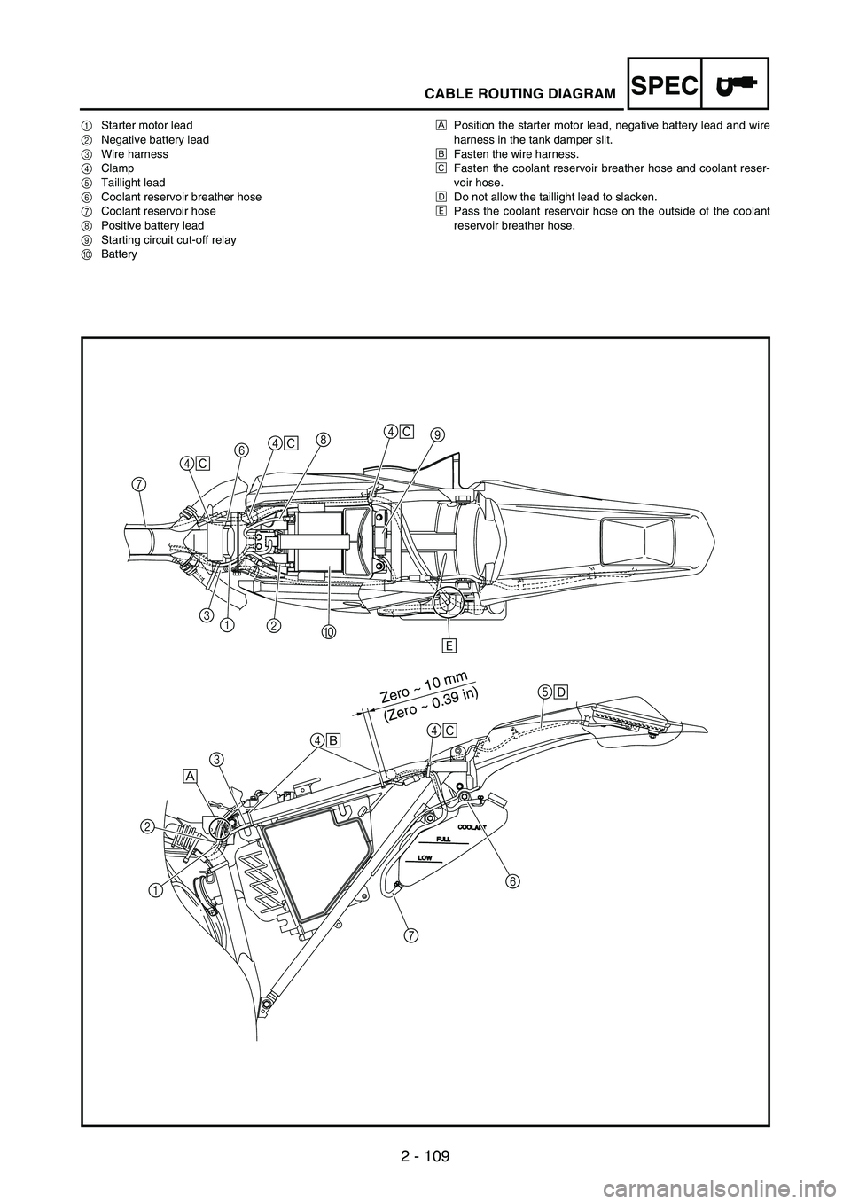
CABLE ROUTING DIAGRAM
1Starter motor lead
2Negative battery lead
3Wire harness
4Clamp
5Taillight lead
6Coolant reservoir breather hose
7Coolant reservoir hose
8Positive battery lead
9Starting circuit cut-off relay
0BatteryÈPosition the starter motor lead, negative battery lead and wire
harness in the tank damper slit.
ÉFasten the wire harness.
ÊFasten the coolant reservoir breather hose and coolant reser-
voir hose.
ËDo not allow the taillight lead to slacken.
ÌPass the coolant reservoir hose on the outside of the coolant
reservoir breather hose.
Zero ~ 10 mm
(Zero ~ 0.39 in)
9
0 1
2 368
Ì 4
Ê
74
Ê4
Ê
4
Ê
5
Ë
4
É
3
È
1 2
6
7
Page 194 of 864

3 - 3
INSP
ADJ
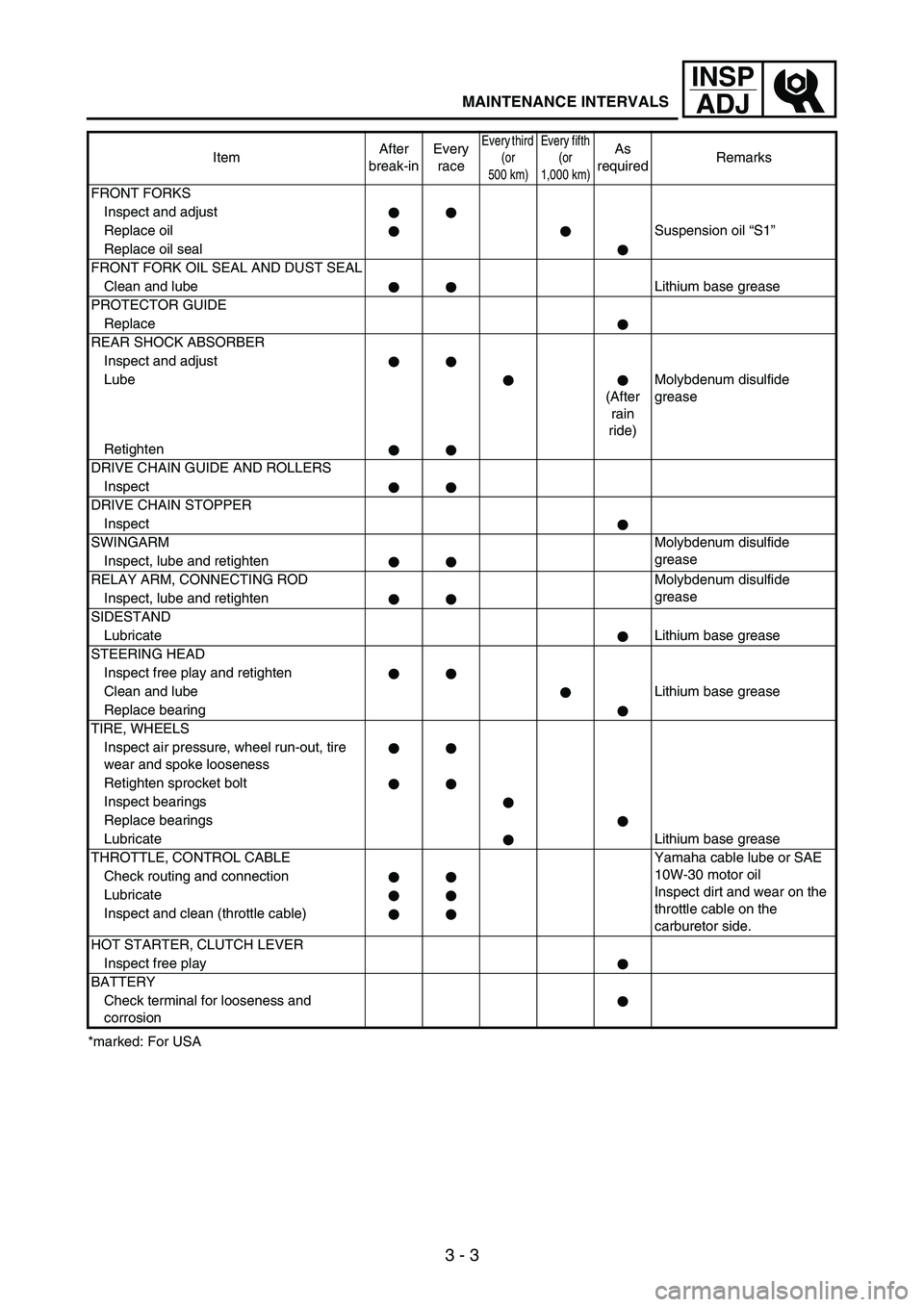
MAINTENANCE INTERVALS
*marked: For USAFRONT FORKS
Inspect and adjust
Replace oilSuspension oil “S1”
Replace oil seal
FRONT FORK OIL SEAL AND DUST SEAL
Clean and lubeLithium base grease
PROTECTOR GUIDE
Replace
REAR SHOCK ABSORBER
Inspect and adjust
Lube
(After
rain
ride)Molybdenum disulfide
grease
Retighten
DRIVE CHAIN GUIDE AND ROLLERS
Inspect
DRIVE CHAIN STOPPER
Inspect
SWINGARMMolybdenum disulfide
grease
Inspect, lube and retighten
RELAY ARM, CONNECTING ROD Molybdenum disulfide
grease
Inspect, lube and retighten
SIDESTAND
LubricateLithium base grease
STEERING HEAD
Inspect free play and retighten
Clean and lubeLithium base grease
Replace bearing
TIRE, WHEELS
Inspect air pressure, wheel run-out, tire
wear and spoke looseness
Retighten sprocket bolt
Inspect bearings
Replace bearings
LubricateLithium base grease
THROTTLE, CONTROL CABLE Yamaha cable lube or SAE
10W-30 motor oil
Inspect dirt and wear on the
throttle cable on the
carburetor side. Check routing and connection
Lubricate
Inspect and clean (throttle cable)
HOT STARTER, CLUTCH LEVER
Inspect free play
BATTERY
Check terminal for looseness and
corrosionItemAfter
break-inEvery
race
Every third
(or
500 km)Every fifth
(or
1,000 km)As
requiredRemarks
Page 700 of 864

5 - 119
CHASSWINGARM
EC570000
SWINGARM
Extent of removal:
1 Swingarm removal
Extent of removal Order Part name Q’ty Remarks
SWINGARM REMOVAL
WARNING
Support the machine securely so there is nodanger of it falling over. Preparation for removal Hold the machine by placing the suitable
stand under the engine.
Brake hose holder
Refer to “FRONT BRAKE AND REAR BRAKE”
section.
Rear brake caliper
Bolt (brake pedal) Shift the brake pedal backward.
Drive chain
1 Drive chain support 1
2 Lower chain tensioner 1
3 Bolt (rear shock absorber-relay arm) 1 Hold the swingarm.
4 Bolt (connecting rod) 1
5 Pivot shaft 1
6 Swingarm 1
1
Page 704 of 864

5 - 123
CHASSWINGARM
EC578000SWINGARM DISASSEMBLY
Extent of removal:
1 Swingarm disassembly
2 Connecting rod removal and disassembly
3 Relay arm removal and disassembly
Extent of removal Order Part name Q’ty Remarks
SWINGARM DISASSEMBLY
1 Cap 2 Refer to “REMOVAL POINTS”.
2 Relay arm 1
3 Connecting rod 1
4 Collar 2
5 Oil seal 2
6 Thrust bearing 2
7 Bushing 2
8 Oil seal 8
9 Bearing 10 Refer to “REMOVAL POINTS”.
1
2
3
23
Page 708 of 864

5 - 127
CHASSWINGARM
EC573000REMOVAL POINTS
Cap
1. Remove:
Left cap
1
NOTE:Remove with a slotted-head screw-
driver inserted under the mark
a on
the left cap.
EC573200Bearing
1. Remove:
Bearing
1
NOTE:Remove the bearing by pressing its
outer race.
INSPECTION
Wash the bearings, bushings, col-
lars, and covers in a solvent.
Swingarm
1. Inspect:
Bearing
1
Bushing
2
Free play exists/unsmooth
revolution/rust
→ Replace
bearing and bushing as a set.
2. Inspect:
Oil seal
3
Damage
→ Replace.
Relay arm
1. Inspect:
Bearing
1
Collar
2
Free play exists/unsmooth
revolution/rust
→ Replace
bearing and collar as a set.
2. Inspect:
Oil seal
3
Damage
→ Replace.
POINTS DE DEPOSE
Capuchon
1. Déposer:
Capuchon gauche 1
N.B.:
Déposer en insérant un tournevis à lame
droite sous le repère a du capuchon
gauche.
Roulement
1. Déposer:
Roulement 1
N.B.:
Enlever le roulement en appuyant sur la
cage externe.
CONTROLE
Nettoyer les roulements, les bagues, les
entretoises épaulées et les caches dans
du solvant.
Bras oscillant
1. Contrôler:
Roulement 1
Bague 2
Jeu/rotation irrégulière/rouille →
Remplacer ensemble le roulement
et la bague.
2. Contrôler:
Bague d’étanchéité 3
Endommagement → Remplacer.
Bras relais
1. Contrôler:
Roulement 1
Entretoise épaulée 2
Jeu/rotation irrégulière/rouille →
Remplacer ensemble le roulement
et l’entretoise épaulée.
2. Contrôler:
Bague d’étanchéité 3
Endommagement → Remplacer.
BRAS OSCILLANT
Page 712 of 864

5 - 131
CHASSWINGARM
2. Install:
Bearing
1
Washer
2
Oil seal
3
To relay arm.
NOTE:Apply the molybdenum disulfide
grease on the bearing when install-
ing.
Install the bearing by pressing it on
the side having the manufacture’s
marks or numbers.
Apply the molybdenum disulfide
grease on the washer.
Installed depth of
bearings a
:
Zero mm (Zero in)
3. Install:
Bearing
1
Oil seal
2
To connecting rod.
NOTE:Apply the molybdenum disulfide
grease on the bearing when install-
ing.
Install the bearing by pressing it on
the side having the manufacture’s
marks or numbers.
Installed depth of
bearings a
:
5 mm (0.20 in)
Swingarm
1. Install:
Bushing
1
Thrust bearing
2
Oil seal
3
Collar
4
To swingarm
5.
NOTE:Apply the molybdenum disulfide
grease on the bushings, thrust bear-
ings, oil seal lips and contact sur-
faces of the collar and thrust bearing.
2. Monter:
Roulement 1
Rondelle 2
Bague d’étanchéité 3
Sur le bras relais.
N.B.:
Lors de l’installation, enduire le roule-
ment de graisse au bisulfure de molyb-
dène.
Monter le roulement en pressant sur le
côté où sont imprimés la marque ou le
numéro du fabricant
Appliquer la graisse au bisulfure de
molybdène sur la rondelle.
Profondeur d’installation
des roulements a:
Zéro mm (zéro in)
3. Monter:
Roulement 1
Bague d’étanchéité 2
Sur la bielle.
N.B.:
Lors de l’installation, enduire le roule-
ment de graisse au bisulfure de molyb-
dène.
Monter le roulement en pressant sur le
côté où sont imprimés la marque ou le
numéro du fabricant.
Profondeur d’installation
des roulements a:
5 mm (0,20 in)
Bras oscillant
1. Monter:
Bague 1
Roulement de butée 2
Bague d’étanchéité 3
Entretoise épaulée 4
Sur le bras oscillant 5.
N.B.:
Appliquer la graisse au bisulfure de
molybdène sur les bagues, les roule-
ments de butée, les lèvres des bagues
d’étanchéité et les surfaces de contact de
lentretoise épaulée et du roulement de
butée.
BRAS OSCILLANT
Page 714 of 864

5 - 133
CHASSWINGARM
2. Install:
Collar
1
Washer
2
To relay arm
3.
NOTE:Apply the molybdenum disulfide
grease on the collars and oil seal
lips.
3. Install:
Collar
1
To connecting rod
2.
NOTE:Apply the molybdenum disulfide
grease on the collar and oil seal lips.
4. Install:
Connecting rod
1
Bolt (connecting rod)
2
Washer
3
Nut (connecting rod)
4
To relay arm
5.
NOTE:Apply the molybdenum disulfide
grease on the bolt.
T R..80 Nm (8.0 m · kg, 58 ft · lb)
5. Install:
Relay arm
1
Bolt (relay arm)
2
Washer
3
Nut (relay arm)
4
To swingarm.
NOTE:Apply the molybdenum disulfide
grease on the bolt.
Do not tighten the nut yet.
6. Install:
Swingarm
1
Pivot shaft
2
NOTE:Apply the molybdenum disulfide
grease on the pivot shaft.
Insert the pivot shaft from right
side.
T R..85 Nm (8.5 m · kg, 61 ft · lb)
2. Monter:
Entretoise épaulée 1
Rondelle 2
Sur le bras relais 3.
N.B.:
Appliquer de la graisse au bisulfure de
molybdène sur les entretoises épaulées et
les lèvres des bagues d’étanchéité.
3. Monter:
Entretoise épaulée 1
Sur la bielle 2.
N.B.:
Appliquer de la graisse au bisulfure de
molybdène sur l’entretoise épaulée et les
lèvres des bagues d’étanchéité.
4. Monter:
Bielle 1
Boulon (bielle) 2
Rondelle 3
Ecrou (bielle) 4
Sur le bras relais 5.
N.B.:
Appliquer de la graisse au bisulfure de
molybdène sur le boulon.
T R..80 Nm (8,0 m · kg, 58 ft · lb)
5. Monter:
Bras relais 1
Boulon (bras relais) 2
Rondelle 3
Ecrou (bras relais) 4
Sur le bras oscillant.
N.B.:
Appliquer de la graisse au bisulfure de
molybdène sur le boulon.
Ne pas encore serrer l’écrou.
6. Monter:
Bras oscillant 1
Boulon-pivot 2
N.B.:
Appliquer de la graisse au bisulfure de
molybdène sur le boulon-pivot.
Insérer le boulon-pivot du côté droit.
T R..85 Nm (8,5 m · kg, 61 ft · lb)
BRAS OSCILLANT
Page 716 of 864

5 - 135
CHASSWINGARM
7. Check:
Swingarm side play
a
Free play exists
→ Replace
thrust bearing.
Swingarm up and down move-
ment
b
Unsmooth movement/binding/
rough spots
→ Grease or
replace bearings, bushings
and collars.
8. Install:
Bolt (connecting rod)
1
Washer
2
Nut (connecting rod)
3
NOTE:Apply the molybdenum disulfide
grease on the bolt.
Do not tighten the nut yet.
9. Install:
Bolt (rear shock absorber-
relay arm)
1
Nut (rear shock absorber-relay
arm)
2
NOTE:Apply the molybdenum disulfide
grease on the bolt.
T R..53 Nm (5.3 m · kg, 38 ft · lb)
10. Tighten:
Nut (connecting rod)
1
T R..80 Nm (8.0 m · kg, 58 ft · lb)
11. Tighten:
Nut (relay arm)
1
T R..80 Nm (8.0 m · kg, 58 ft · lb)
7. Contrôler:
Jeu latéral du bras oscillant a
Jeu → Remplacer le roulement de
butée.
Mouvement de bas en haut du
bras oscillant b
Mouvement irrégulier/coince-
ment/rugosités → Graisser ou
remplacer les roulements, les
bagues et les entretoises épaulées.
8. Monter:
Boulon (bielle) 1
Rondelle 2
Ecrou (bielle) 3
N.B.:
Appliquer de la graisse au bisulfure de
molybdène sur le boulon.
Ne pas encore serrer l’écrou.
9. Monter:
Boulon (amortisseur arrière –
bras relais) 1
Ecrou (amortisseur arrière – bras
relais) 2
N.B.:
Appliquer de la graisse au bisulfure de
molybdène sur le boulon.
T R..53 Nm (5,3 m · kg, 38 ft · lb)
10. Serrer:
Ecrou (bielle) 1
T R..80 Nm (8,0 m · kg, 58 ft · lb)
11. Serrer:
Ecrou (bras relais) 1
T R..80 Nm (8,0 m · kg, 58 ft · lb)
BRAS OSCILLANT