Fork oil YAMAHA WR 250F 2005 Owners Manual
[x] Cancel search | Manufacturer: YAMAHA, Model Year: 2005, Model line: WR 250F, Model: YAMAHA WR 250F 2005Pages: 864, PDF Size: 18.1 MB
Page 22 of 864
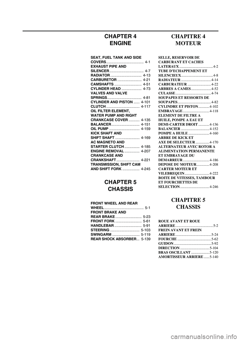
CHAPTER 4
ENGINE
SEAT, FUEL TANK AND SIDE
COVERS..................................... 4-1
EXHAUST PIPE AND
SILENCER.................................. 4-7
RADIATOR............................... 4-13
CARBURETOR........................ 4-21
CAMSHAFTS........................... 4-51
CYLINDER HEAD.................... 4-73
VALVES AND VALVE
SPRINGS.................................. 4-81
CYLINDER AND PISTON...... 4-101
CLUTCH................................. 4-117
OIL FILTER ELEMENT,
WATER PUMP AND RIGHT
CRANKCASE COVER........... 4-135
BALANCER............................ 4-151
OIL PUMP.............................. 4-159
KICK SHAFT AND
SHIFT SHAFT........................ 4-169
AC MAGNETO AND
STARTER CLUTCH............... 4-185
ENGINE REMOVAL............... 4-207
CRANKCASE AND
CRANKSHAFT....................... 4-221
TRANSMISSION, SHIFT CAM
AND SHIFT FORK................. 4-245
CHAPTER 5
CHASSIS
FRONT WHEEL AND REAR
WHEEL....................................... 5-1
FRONT BRAKE AND
REAR BRAKE.......................... 5-23
FRONT FORK.......................... 5-61
HANDLEBAR........................... 5-91
STEERING............................. 5-103
SWINGARM........................... 5-119
REAR SHOCK ABSORBER... 5-139
CHAPITRE 4
MOTEUR
SELLE, RESERVOIR DE
CARBURANT ET CACHES
LATERAUX..................................... 4-2
TUBE D’ECHAPPEMENT ET
SILENCIEUX................................... 4-8
RADIATEUR................................. 4-14
CARBURATEUR.......................... 4-22
ARBRES A CAMES...................... 4-52
CULASSE....................................... 4-74
SOUPAPES ET RESSORTS DE
SOUPAPES..................................... 4-82
CYLINDRE ET PISTON............ 4-102
EMBRAYAGE............................. 4-118
ELEMENT DE FILTRE A
HUILE, POMPE A EAU ET
DEMI-CARTER DROIT............ 4-136
BALANCIER............................... 4-152
POMPE A HUILE....................... 4-160
ARBRE DE KICK ET
AXE DE SELECTEUR............... 4-170
ALTERNATEUR AVEC ROTOR A
ALIMENTATION PERMANENTE
ET EMBRAYAGE DU
DEMARREUR............................. 4-186
DEPOSE DU MOTEUR.............. 4-208
CARTER MOTEUR ET
VILEBREQUIN........................... 4-222
BOITE DE VITESSES, TAMBOUR
ET FOURCHETTES DE
SELECTION................................ 4-246
CHAPITRE 5
CHASSIS
ROUE AVANT ET ROUE
ARRIERE......................................... 5-2
FREIN AVANT ET FREIN
ARRIERE....................................... 5-24
FOURCHE..................................... 5-62
GUIDON......................................... 5-92
DIRECTION................................ 5-104
BRAS OSCILLANT.................... 5-120
AMORTISSEUR ARRIERE...... 5-140
Page 26 of 864
1 - 1
GEN
INFODESCRIPTION
EC100000
GENERAL INFORMATION
EC110000
DESCRIPTION
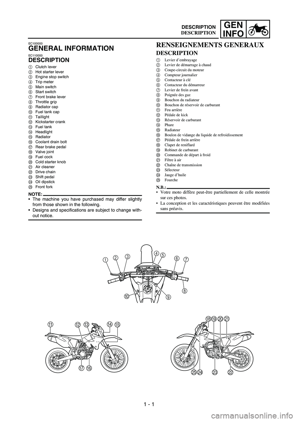
1Clutch lever
2Hot starter lever
3Engine stop switch
4Trip meter
5Main switch
6Start switch
7Front brake lever
8Throttle grip
9Radiator cap
0Fuel tank cap
ATaillight
BKickstarter crank
CFuel tank
DHeadlight
ERadiator
FCoolant drain bolt
GRear brake pedal
HValve joint
IFuel cock
JCold starter knob
KAir cleaner
LDrive chain
MShift pedal
NOil dipstick
OFront fork
NOTE:The machine you have purchased may differ slightly
from those shown in the following.
Designs and specifications are subject to change with-
out notice.
1234
5
6
7
8
9 0
A
BCDE
F G
HIJK
L M
N O
RENSEIGNEMENTS GENERAUX
DESCRIPTION
1Levier d’embrayage
2Levier de démarrage à chaud
3Coupe-circuit du moteur
4Compteur journalier
5Contacteur à clé
6Contacteur du démarreur
7Levier de frein avant
8Poignée des gaz
9Bouchon du radiateur
0Bouchon de réservoir de carburant
AFeu arrière
BPédale de kick
CRéservoir de carburant
DPhare
ERadiateur
FBoulon de vidange du liquide de refroidissement
GPédale de frein arrière
HClapet de reniflard
IRobinet de carburant
JCommande de départ à froid
KFiltre à air
LChaîne de transmission
MSélecteur
NJauge d’huile
OFourche
N.B.:
Votre moto diffère peut-être partiellement de celle montrée
sur ces photos.
La conception et les caractéristiques peuvent être modifiées
sans préavis.
DESCRIPTION
Page 36 of 864
1 - 11
GEN
INFO
SPECIAL TOOLS
SPECIAL TOOLS
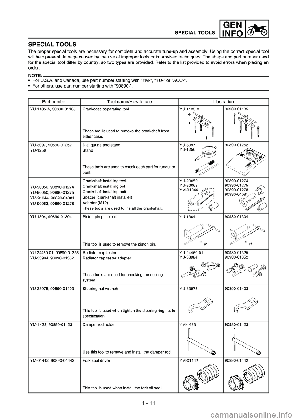
The proper special tools are necessary for complete and accurate tune-up and assembly. Using the correct special tool
will help prevent damage caused by the use of improper tools or improvised techniques. The shape and part number used
for the special tool differ by country, so two types are provided. Refer to the list provided to avoid errors when placing an
order.
NOTE:For U.S.A. and Canada, use part number starting with “YM-”, “YU-” or “ACC-”.
For others, use part number starting with “90890-”.
Part number Tool name/How to use Illustration
YU-1135-A, 90890-01135 Crankcase separating tool
These tool is used to remove the crankshaft from
either case.
YU-3097, 90890-01252
YU-1256Dial gauge and stand
Stand
These tools are used to check each part for runout or
bent.
YU-90050, 90890-01274
YU-90050, 90890-01275
YM-91044, 90890-04081
YU-90063, 90890-01278Crankshaft installing tool
Crankshaft installing pot
Crankshaft installing bolt
Spacer (crankshaft installer)
Adapter (M12)
These tools are used to install the crankshaft.
YU-1304, 90890-01304 Piston pin puller set
This tool is used to remove the piston pin.
YU-24460-01, 90890-01325
YU-33984, 90890-01352Radiator cap tester
Radiator cap tester adapter
These tools are used for checking the cooling
system.
YU-33975, 90890-01403 Steering nut wrench
This tool is used when tighten the steering ring nut to
specification.
YM-1423, 90890-01423 Damper rod holder
Use this tool to remove and install the damper rod.
YM-01442, 90890-01442 Fork seal driver
This tool is used when install the fork oil seal.
Page 70 of 864
1 - 45
GEN
INFO
TORQUE-CHECK POINTS
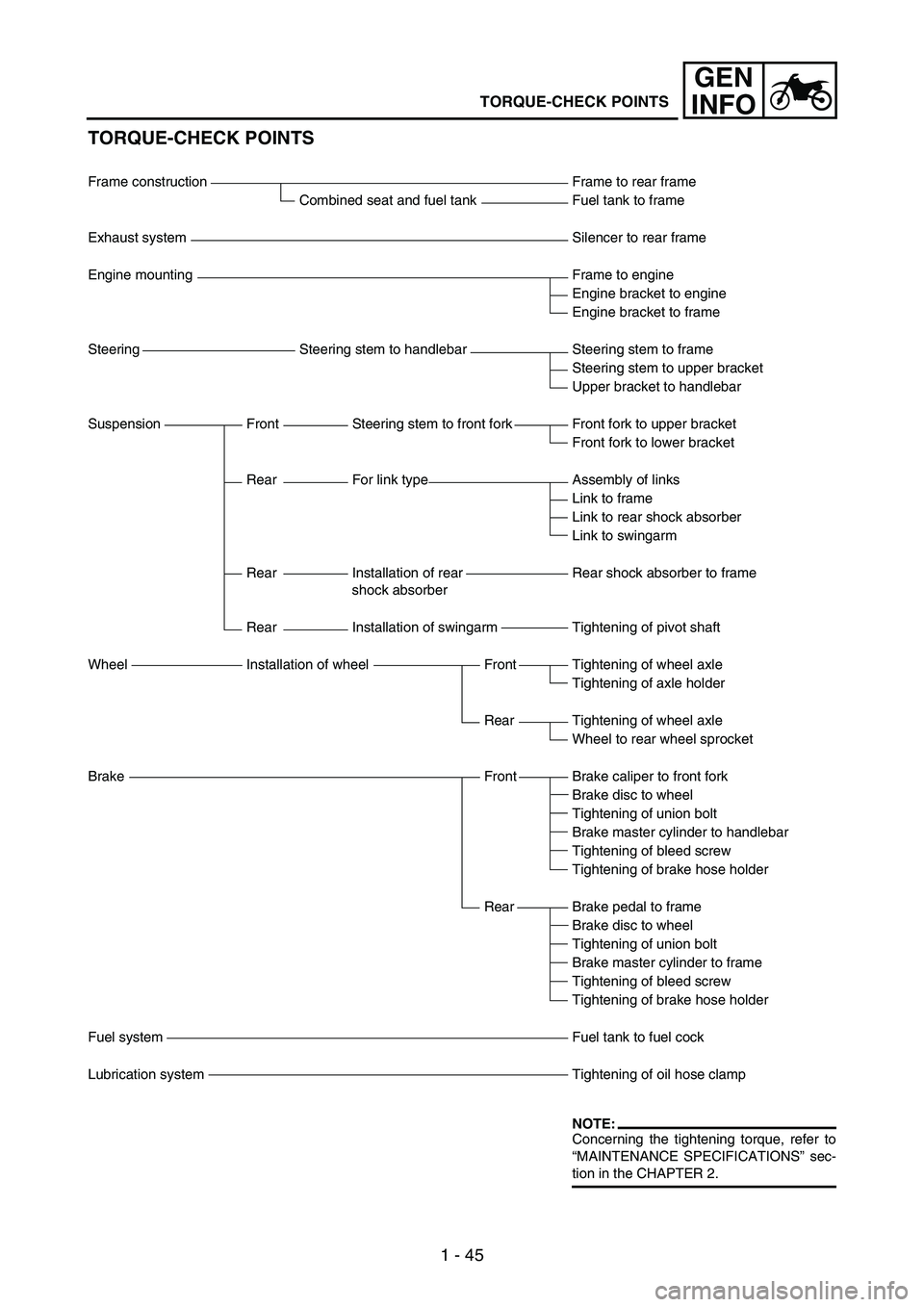
Frame construction Frame to rear frame
Combined seat and fuel tank Fuel tank to frame
Exhaust system Silencer to rear frame
Engine mounting Frame to engine
Engine bracket to engine
Engine bracket to frame
Steering Steering stem to handlebar Steering stem to frame
Steering stem to upper bracket
Upper bracket to handlebar
Suspension Front Steering stem to front fork Front fork to upper bracket
Front fork to lower bracket
Rear For link type Assembly of links
Link to frame
Link to rear shock absorber
Link to swingarm
Rear Installation of rear
shock absorberRear shock absorber to frame
Rear Installation of swingarm Tightening of pivot shaft
Wheel Installation of wheel Front Tightening of wheel axle
Tightening of axle holder
Rear Tightening of wheel axle
Wheel to rear wheel sprocket
Brake Front Brake caliper to front fork
Brake disc to wheel
Tightening of union bolt
Brake master cylinder to handlebar
Tightening of bleed screw
Tightening of brake hose holder
Rear Brake pedal to frame
Brake disc to wheel
Tightening of union bolt
Brake master cylinder to frame
Tightening of bleed screw
Tightening of brake hose holder
Fuel system Fuel tank to fuel cock
Lubrication system Tightening of oil hose clamp
NOTE:Concerning the tightening torque, refer to
“MAINTENANCE SPECIFICATIONS” sec-
tion in the CHAPTER 2.
TORQUE-CHECK POINTS
Page 82 of 864
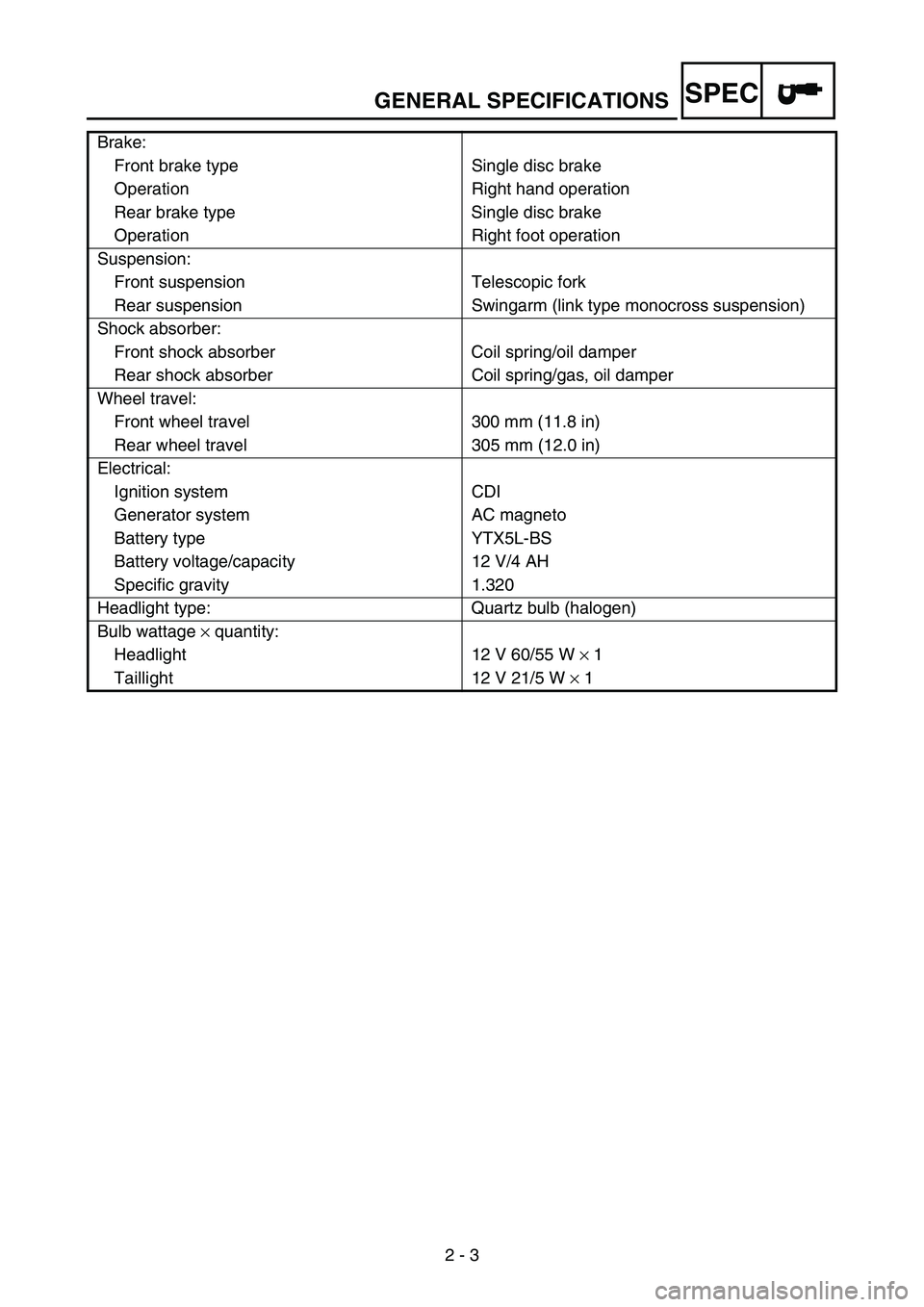
GENERAL SPECIFICATIONS
2 - 3
SPEC
Brake:
Front brake type Single disc brake
Operation Right hand operation
Rear brake type Single disc brake
Operation Right foot operation
Suspension:
Front suspension Telescopic fork
Rear suspension Swingarm (link type monocross suspension)
Shock absorber:
Front shock absorber Coil spring/oil damper
Rear shock absorber Coil spring/gas, oil damper
Wheel travel:
Front wheel travel 300 mm (11.8 in)
Rear wheel travel 305 mm (12.0 in)
Electrical:
Ignition system CDI
Generator system AC magneto
Battery type YTX5L-BS
Battery voltage/capacity 12 V/4 AH
Specific gravity 1.320
Headlight type: Quartz bulb (halogen)
Bulb wattage × quantity:
Headlight 12 V 60/55 W × 1
Taillight 12 V 21/5 W × 1
Page 91 of 864
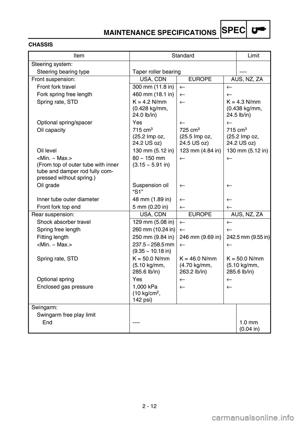
MAINTENANCE SPECIFICATIONS
2 - 12
SPEC
CHASSIS
Item Standard Limit
Steering system:
Steering bearing type Taper roller bearing ----
Front suspension: USA, CDN EUROPE AUS, NZ, ZA
Front fork travel 300 mm (11.8 in)←←
Fork spring free length 460 mm (18.1 in)←←
Spring rate, STD K = 4.2 N/mm
(0.428 kg/mm,
24.0 lb/in)←K = 4.3 N/mm
(0.438 kg/mm,
24.5 lb/in)
Optional spring/spacer Yes←←
Oil capacity 715 cm
3
(25.2 Imp oz,
24.2 US oz) 725 cm3
(25.5 Imp oz,
24.5 US oz) 715 cm3
(25.2 Imp oz,
24.2 US oz)
Oil level 130 mm (5.12 in) 123 mm (4.84 in) 130 mm (5.12 in)
(From top of outer tube with inner
tube and damper rod fully com-
pressed without spring.)80 ~ 150 mm
(3.15 ~ 5.91 in)←←
Oil grade Suspension oil
“S1”←←
Inner tube outer diameter 48 mm (1.89 in)←←
Front fork top end 5 mm (0.20 in)←←
Rear suspension: USA, CDN EUROPE AUS, NZ, ZA
Shock absorber travel 129 mm (5.08 in)← ←
Spring free length260 mm (10.24 in)← ←
Fitting length 250 mm (9.84 in) 246 mm (9.69 in) 242.5 mm (9.55 in)
(9.35 ~ 10.18 in)← ←
Spring rate, STD K = 50.0 N/mm
(5.10 kg/mm,
285.6 lb/in)K = 46.0 N/mm
(4.70 kg/mm,
263.2 lb/in)K = 50.0 N/mm
(5.10 kg/mm,
285.6 lb/in)
Optional spring Yes← ←
Enclosed gas pressure 1,000 kPa
(10 kg/cm
2,
142 psi)← ←
Swingarm:
Swingarm free play limit
End ---- 1.0 mm
(0.04 in)
Page 192 of 864
3 - 1
INSP
ADJ
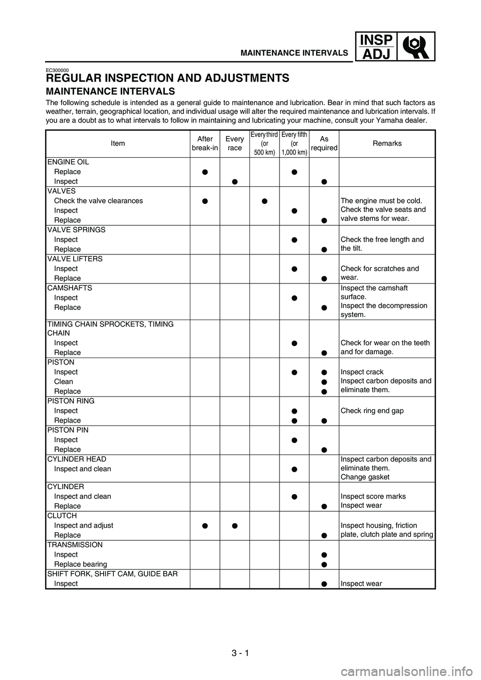
MAINTENANCE INTERVALS
EC300000
REGULAR INSPECTION AND ADJUSTMENTS
MAINTENANCE INTERVALS
The following schedule is intended as a general guide to maintenance and lubrication. Bear in mind that such factors as
weather, terrain, geographical location, and individual usage will alter the required maintenance and lubrication intervals. If
you are a doubt as to what intervals to follow in maintaining and lubricating your machine, consult your Yamaha dealer.
ItemAfter
break-inEvery
race
Every third
(or
500 km)Every fifth
(or
1,000 km)As
requiredRemarks
ENGINE OIL
Replace
Inspect
VALVES
Check the valve clearances The engine must be cold.
Check the valve seats and
valve stems for wear. Inspect
Replace
VALVE SPRINGS
InspectCheck the free length and
the tilt.
Replace
VALVE LIFTERS
InspectCheck for scratches and
wear.
Replace
CAMSHAFTSInspect the camshaft
surface.
Inspect the decompression
system. Inspect
Replace
TIMING CHAIN SPROCKETS, TIMING
CHAIN
InspectCheck for wear on the teeth
and for damage.
Replace
PISTON
InspectInspect crack
Inspect carbon deposits and
eliminate them. Clean
Replace
PISTON RING
InspectCheck ring end gap
Replace
PISTON PIN
Inspect
Replace
CYLINDER HEADInspect carbon deposits and
eliminate them.
Change gasket Inspect and clean
CYLINDER
Inspect and clean Inspect score marks
Inspect wear
Replace
CLUTCH
Inspect and adjust Inspect housing, friction
plate, clutch plate and spring
Replace
TRANSMISSION
Inspect
Replace bearing
SHIFT FORK, SHIFT CAM, GUIDE BAR
InspectInspect wear
Page 194 of 864
3 - 3
INSP
ADJ
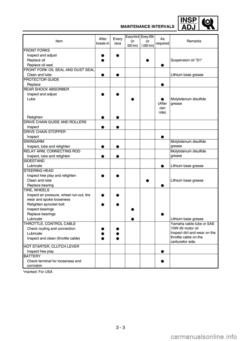
MAINTENANCE INTERVALS
*marked: For USAFRONT FORKS
Inspect and adjust
Replace oilSuspension oil “S1”
Replace oil seal
FRONT FORK OIL SEAL AND DUST SEAL
Clean and lubeLithium base grease
PROTECTOR GUIDE
Replace
REAR SHOCK ABSORBER
Inspect and adjust
Lube
(After
rain
ride)Molybdenum disulfide
grease
Retighten
DRIVE CHAIN GUIDE AND ROLLERS
Inspect
DRIVE CHAIN STOPPER
Inspect
SWINGARMMolybdenum disulfide
grease
Inspect, lube and retighten
RELAY ARM, CONNECTING ROD Molybdenum disulfide
grease
Inspect, lube and retighten
SIDESTAND
LubricateLithium base grease
STEERING HEAD
Inspect free play and retighten
Clean and lubeLithium base grease
Replace bearing
TIRE, WHEELS
Inspect air pressure, wheel run-out, tire
wear and spoke looseness
Retighten sprocket bolt
Inspect bearings
Replace bearings
LubricateLithium base grease
THROTTLE, CONTROL CABLE Yamaha cable lube or SAE
10W-30 motor oil
Inspect dirt and wear on the
throttle cable on the
carburetor side. Check routing and connection
Lubricate
Inspect and clean (throttle cable)
HOT STARTER, CLUTCH LEVER
Inspect free play
BATTERY
Check terminal for looseness and
corrosionItemAfter
break-inEvery
race
Every third
(or
500 km)Every fifth
(or
1,000 km)As
requiredRemarks
Page 207 of 864
3 - 16
INSP
ADJ
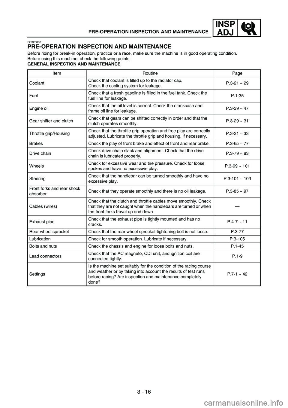
PRE-OPERATION INSPECTION AND MAINTENANCE
EC320000
PRE-OPERATION INSPECTION AND MAINTENANCE
Before riding for break-in operation, practice or a race, make sure the machine is in good operating condition.
Before using this machine, check the following points.
GENERAL INSPECTION AND MAINTENANCE
Item Routine Page
CoolantCheck that coolant is filled up to the radiator cap.
Check the cooling system for leakage.P.3-21 ~ 29
FuelCheck that a fresh gasoline is filled in the fuel tank. Check the
fuel line for leakage.P.1-35
Engine oilCheck that the oil level is correct. Check the crankcase and
frame oil line for leakage.P.3-39 ~ 47
Gear shifter and clutchCheck that gears can be shifted correctly in order and that the
clutch operates smoothly.P.3-29 ~ 31
Throttle grip/HousingCheck that the throttle grip operation and free play are correctly
adjusted. Lubricate the throttle grip and housing, if necessary.P.3-31 ~ 33
Brakes Check the play of front brake and effect of front and rear brake. P.3-65 ~ 77
Drive chainCheck drive chain slack and alignment. Check that the drive
chain is lubricated properly.P.3-79 ~ 83
WheelsCheck for excessive wear and tire pressure. Check for loose
spokes and have no excessive play.P.3-99 ~ 101
SteeringCheck that the handlebar can be turned smoothly and have no
excessive play.P.3-101 ~ 103
Front forks and rear shock
absorberCheck that they operate smoothly and there is no oil leakage. P.3-85 ~ 97
Cables (wires)Check that the clutch and throttle cables move smoothly. Check
that they are not caught when the handlebars are turned or when
the front forks travel up and down.—
Exhaust pipeCheck that the exhaust pipe is tightly mounted and has no
cracks.P.4-7 ~ 11
Rear wheel sprocket Check that the rear wheel sprocket tightening bolt is not loose. P.3-77
Lubrication Check for smooth operation. Lubricate if necessary. P.3-105
Bolts and nuts Check the chassis and engine for loose bolts and nuts. P.1-45
Lead connectorsCheck that the AC magneto, CDI unit, and ignition coil are
connected tightly.P.1-9
SettingsIs the machine set suitably for the condition of the racing course
and weather or by taking into account the results of test runs
before racing? Are inspection and maintenance completely
done?P.7-1 ~ 42
Page 276 of 864
3 - 85
INSP
ADJ
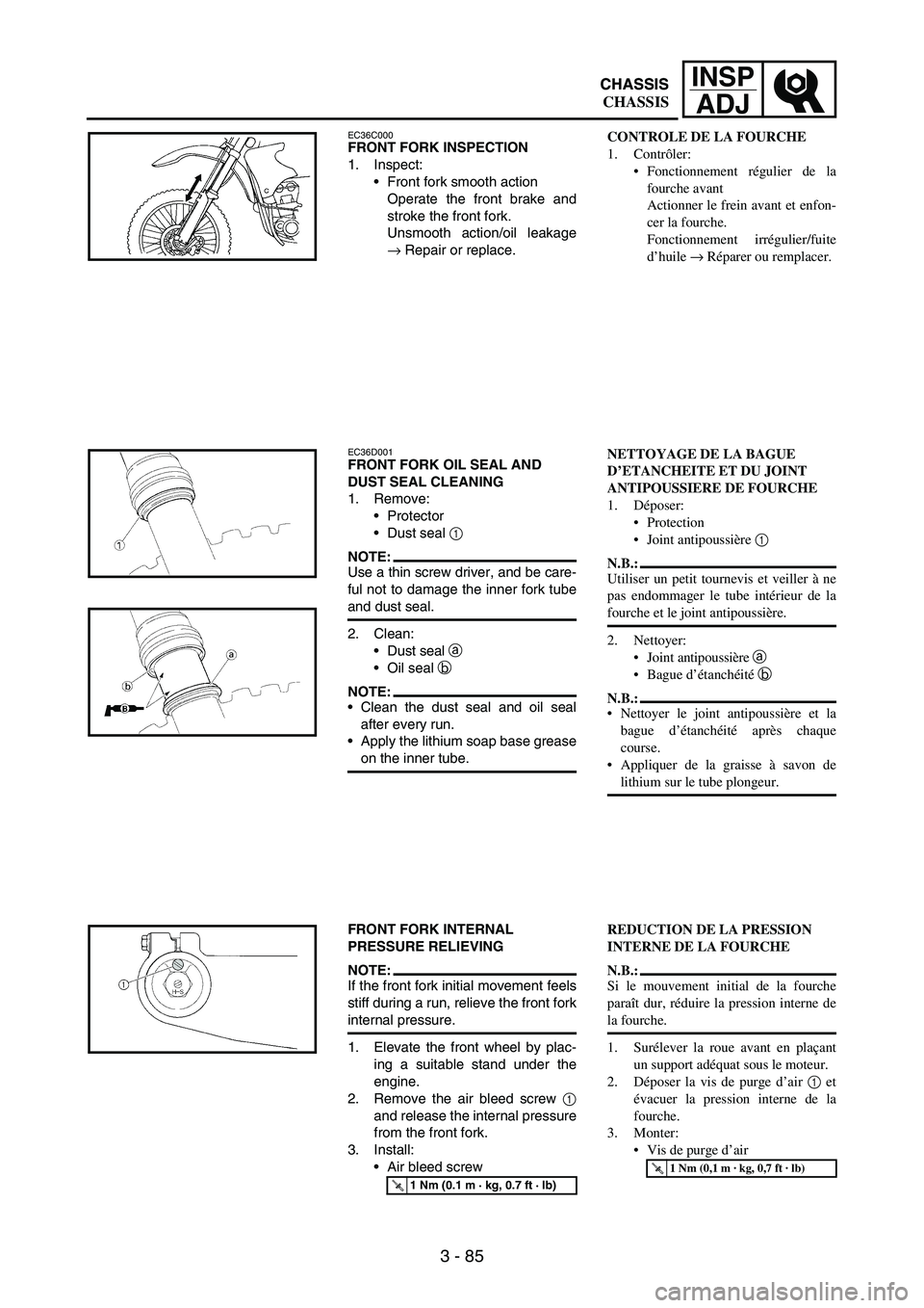
EC36C000FRONT FORK INSPECTION
1. Inspect:
Front fork smooth action
Operate the front brake and
stroke the front fork.
Unsmooth action/oil leakage
→ Repair or replace.
EC36D001FRONT FORK OIL SEAL AND
DUST SEAL CLEANING
1. Remove:
Protector
Dust seal
1
NOTE:Use a thin screw driver, and be care-
ful not to damage the inner fork tube
and dust seal.
2. Clean:
Dust seal
a
Oil seal
b
NOTE:Clean the dust seal and oil seal
after every run.
Apply the lithium soap base grease
on the inner tube.
FRONT FORK INTERNAL
PRESSURE RELIEVING
NOTE:If the front fork initial movement feels
stiff during a run, relieve the front fork
internal pressure.
1. Elevate the front wheel by plac-
ing a suitable stand under the
engine.
2. Remove the air bleed screw
1
and release the internal pressure
from the front fork.
3. Install:
Air bleed screw
T R..1 Nm (0.1 m · kg, 0.7 ft · lb)
CONTROLE DE LA FOURCHE
1. Contrôler:
Fonctionnement régulier de la
fourche avant
Actionner le frein avant et enfon-
cer la fourche.
Fonctionnement irrégulier/fuite
d’huile → Réparer ou remplacer.
NETTOYAGE DE LA BAGUE
D’ETANCHEITE ET DU JOINT
ANTIPOUSSIERE DE FOURCHE
1. Déposer:
Protection
Joint antipoussière 1
N.B.:
Utiliser un petit tournevis et veiller à ne
pas endommager le tube intérieur de la
fourche et le joint antipoussière.
2. Nettoyer:
Joint antipoussière a
Bague d’étanchéité b
N.B.:
Nettoyer le joint antipoussière et la
bague d’étanchéité après chaque
course.
Appliquer de la graisse à savon de
lithium sur le tube plongeur.
REDUCTION DE LA PRESSION
INTERNE DE LA FOURCHE
N.B.:
Si le mouvement initial de la fourche
paraît dur, réduire la pression interne de
la fourche.
1. Surélever la roue avant en plaçant
un support adéquat sous le moteur.
2. Déposer la vis de purge d’air 1 et
évacuer la pression interne de la
fourche.
3. Monter:
Vis de purge d’air
T R..1 Nm (0,1 m · kg, 0,7 ft · lb)
CHASSIS
CHASSIS CHASSIS