coolant YAMAHA WR 250F 2005 Owners Manual
[x] Cancel search | Manufacturer: YAMAHA, Model Year: 2005, Model line: WR 250F, Model: YAMAHA WR 250F 2005Pages: 864, PDF Size: 18.1 MB
Page 26 of 864
1 - 1
GEN
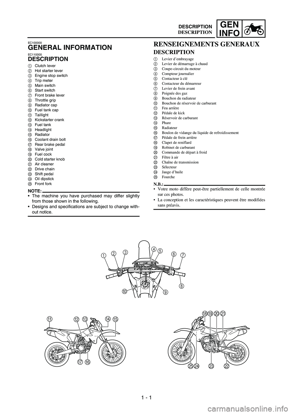
INFODESCRIPTION
EC100000
GENERAL INFORMATION
EC110000
DESCRIPTION
1Clutch lever
2Hot starter lever
3Engine stop switch
4Trip meter
5Main switch
6Start switch
7Front brake lever
8Throttle grip
9Radiator cap
0Fuel tank cap
ATaillight
BKickstarter crank
CFuel tank
DHeadlight
ERadiator
FCoolant drain bolt
GRear brake pedal
HValve joint
IFuel cock
JCold starter knob
KAir cleaner
LDrive chain
MShift pedal
NOil dipstick
OFront fork
NOTE:The machine you have purchased may differ slightly
from those shown in the following.
Designs and specifications are subject to change with-
out notice.
1234
5
6
7
8
9 0
A
BCDE
F G
HIJK
L M
N O
RENSEIGNEMENTS GENERAUX
DESCRIPTION
1Levier d’embrayage
2Levier de démarrage à chaud
3Coupe-circuit du moteur
4Compteur journalier
5Contacteur à clé
6Contacteur du démarreur
7Levier de frein avant
8Poignée des gaz
9Bouchon du radiateur
0Bouchon de réservoir de carburant
AFeu arrière
BPédale de kick
CRéservoir de carburant
DPhare
ERadiateur
FBoulon de vidange du liquide de refroidissement
GPédale de frein arrière
HClapet de reniflard
IRobinet de carburant
JCommande de départ à froid
KFiltre à air
LChaîne de transmission
MSélecteur
NJauge d’huile
OFourche
N.B.:
Votre moto diffère peut-être partiellement de celle montrée
sur ces photos.
La conception et les caractéristiques peuvent être modifiées
sans préavis.
DESCRIPTION
Page 64 of 864
1 - 39
GEN
INFO
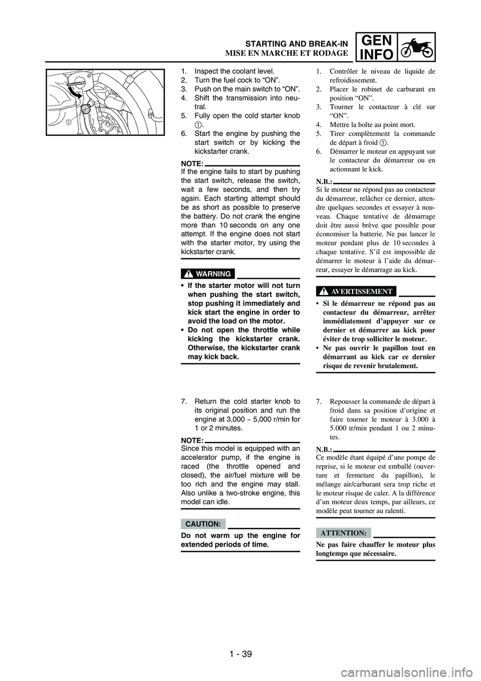
1. Inspect the coolant level.
2. Turn the fuel cock to “ON”.
3. Push on the main switch to “ON”.
4. Shift the transmission into neu-
tral.
5. Fully open the cold starter knob
1.
6. Start the engine by pushing the
start switch or by kicking the
kickstarter crank.
NOTE:If the engine fails to start by pushing
the start switch, release the switch,
wait a few seconds, and then try
again. Each starting attempt should
be as short as possible to preserve
the battery. Do not crank the engine
more than 10 seconds on any one
attempt. If the engine does not start
with the starter motor, try using the
kickstarter crank.
WARNING
If the starter motor will not turn
when pushing the start switch,
stop pushing it immediately and
kick start the engine in order to
avoid the load on the motor.
Do not open the throttle while
kicking the kickstarter crank.
Otherwise, the kickstarter crank
may kick back.
7. Return the cold starter knob to
its original position and run the
engine at 3,000 ~ 5,000 r/min for
1 or 2 minutes.
NOTE:Since this model is equipped with an
accelerator pump, if the engine is
raced (the throttle opened and
closed), the air/fuel mixture will be
too rich and the engine may stall.
Also unlike a two-stroke engine, this
model can idle.
CAUTION:
Do not warm up the engine for
extended periods of time.1. Contrôler le niveau de liquide de
refroidissement.
2. Placer le robinet de carburant en
position “ON”.
3. Tourner le contacteur à clé sur
“ON”.
4. Mettre la boîte au point mort.
5. Tirer complètement la commande
de départ à froid 1.
6. Démarrer le moteur en appuyant sur
le contacteur du démarreur ou en
actionnant le kick.
N.B.:
Si le moteur ne répond pas au contacteur
du démarreur, relâcher ce dernier, atten-
dre quelques secondes et essayer à nou-
veau. Chaque tentative de démarrage
doit être aussi brève que possible pour
économiser la batterie. Ne pas lancer le
moteur pendant plus de 10 secondes à
chaque tentative. S’il est impossible de
démarrer le moteur à l’aide du démar-
reur, essayer le démarrage au kick.
AVERTISSEMENT
Si le démarreur ne répond pas au
contacteur du démarreur, arrêter
immédiatement d’appuyer sur ce
dernier et démarrer au kick pour
éviter de trop solliciter le moteur.
Ne pas ouvrir le papillon tout en
démarrant au kick car ce dernier
risque de revenir brutalement.
7. Repousser la commande de départ à
froid dans sa position d’origine et
faire tourner le moteur à 3.000 à
5.000 tr/min pendant 1 ou 2 minu-
tes.
N.B.:
Ce modèle étant équipé d’une pompe de
reprise, si le moteur est emballé (ouver-
ture et fermeture du papillon), le
mélange air/carburant sera trop riche et
le moteur risque de caler. A la différence
d’un moteur deux temps, par ailleurs, ce
modèle peut tourner au ralenti.
ATTENTION:
Ne pas faire chauffer le moteur plus
longtemps que nécessaire.
STARTING AND BREAK-IN
MISE EN MARCHE ET RODAGE
Page 81 of 864
GENERAL SPECIFICATIONS
2 - 2
SPEC
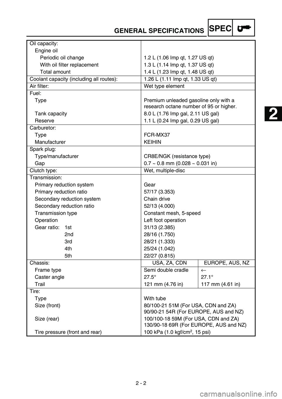
Oil capacity:
Engine oil
Periodic oil change 1.2 L (1.06 Imp qt, 1.27 US qt)
With oil filter replacement 1.3 L (1.14 Imp qt, 1.37 US qt)
Total amount 1.4 L (1.23 Imp qt, 1.48 US qt)
Coolant capacity (including all routes): 1.26 L (1.11 Imp qt, 1.33 US qt)
Air filter: Wet type element
Fuel:
Type Premium unleaded gasoline only with a
research octane number of 95 or higher.
Tank capacity 8.0 L (1.76 Imp gal, 2.11 US gal)
Reserve 1.1 L (0.24 Imp gal, 0.29 US gal)
Carburetor:
Type FCR-MX37
Manufacturer KEIHIN
Spark plug:
Type/manufacturer CR8E/NGK (resistance type)
Gap 0.7 ~ 0.8 mm (0.028 ~ 0.031 in)
Clutch type: Wet, multiple-disc
Transmission:
Primary reduction system Gear
Primary reduction ratio 57/17 (3.353)
Secondary reduction system Chain drive
Secondary reduction ratio 52/13 (4.000)
Transmission type Constant mesh, 5-speed
Operation Left foot operation
Gear ratio: 1st 31/13 (2.385)
2nd 28/16 (1.750)
3rd 28/21 (1.333)
4th 25/24 (1.042)
5th 22/27 (0.815)
Chassis: USA, ZA, CDN EUROPE, AUS, NZ
Frame type Semi double cradle←
Caster angle 27.5°27.1°
Trail 121 mm (4.76 in) 117 mm (4.61 in)
Tire:
Type With tube
Size (front) 80/100-21 51M (For USA, CDN and ZA)
90/90-21 54R (For EUROPE, AUS and NZ)
Size (rear) 100/100-18 59M (For USA, CDN and ZA)
130/90-18 69R (For EUROPE, AUS and NZ)
Tire pressure (front and rear) 100 kPa (1.0 kgf/cm
2, 15 psi)
1
2
3
4
5
6
7
Page 89 of 864
MAINTENANCE SPECIFICATIONS
2 - 10
SPEC
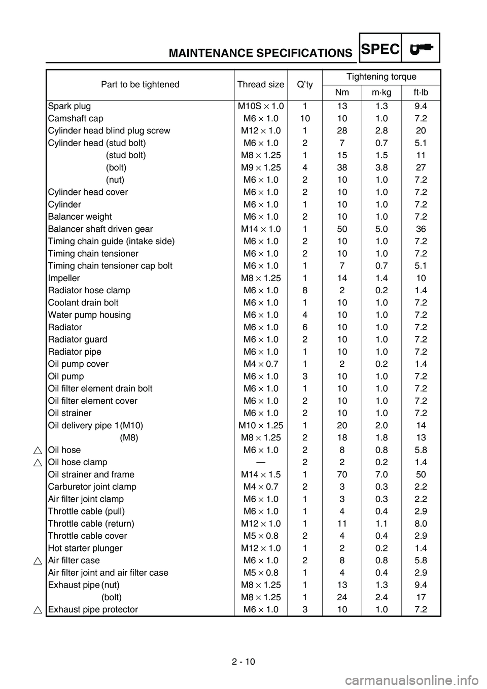
Part to be tightened Thread size Q’tyTightening torque
Nm m·kg ft·lb
Spark plug M10S × 1.0 1 13 1.3 9.4
Camshaft cap M6 × 1.0 10 10 1.0 7.2
Cylinder head blind plug screw M12 × 1.0 1 28 2.8 20
Cylinder head (stud bolt) M6 × 1.0 2 7 0.7 5.1
(stud bolt) M8 × 1.25 1 15 1.5 11
(bolt) M9 × 1.25 4 38 3.8 27
(nut) M6 × 1.0 2 10 1.0 7.2
Cylinder head cover M6 × 1.0 2 10 1.0 7.2
Cylinder M6 × 1.0 1 10 1.0 7.2
Balancer weight M6 × 1.0 2 10 1.0 7.2
Balancer shaft driven gear M14 × 1.0 1 50 5.0 36
Timing chain guide (intake side) M6 × 1.0 2 10 1.0 7.2
Timing chain tensioner M6 × 1.0 2 10 1.0 7.2
Timing chain tensioner cap bolt M6 × 1.0 1 7 0.7 5.1
Impeller M8 × 1.25 1 14 1.4 10
Radiator hose clamp M6 × 1.0 8 2 0.2 1.4
Coolant drain bolt M6 × 1.0 1 10 1.0 7.2
Water pump housing M6 × 1.0 4 10 1.0 7.2
Radiator M6 × 1.0 6 10 1.0 7.2
Radiator guard M6 × 1.0 2 10 1.0 7.2
Radiator pipe M6 × 1.0 1 10 1.0 7.2
Oil pump cover M4 × 0.7 1 2 0.2 1.4
Oil pump M6 × 1.0 3 10 1.0 7.2
Oil filter element drain bolt M6 × 1.0 1 10 1.0 7.2
Oil filter element cover M6 × 1.0 2 10 1.0 7.2
Oil strainer M6 × 1.0 2 10 1.0 7.2
Oil delivery pipe 1 (M10) M10 × 1.25 1 20 2.0 14
(M8) M8 × 1.25 2 18 1.8 13
Oil hose M6 × 1.0 2 8 0.8 5.8
Oil hose clamp—220.21.4
Oil strainer and frame M14 × 1.5 1 70 7.0 50
Carburetor joint clamp M4 × 0.7 2 3 0.3 2.2
Air filter joint clamp M6 × 1.0 1 3 0.3 2.2
Throttle cable (pull) M6 × 1.0 1 4 0.4 2.9
Throttle cable (return) M12 × 1.0 1 11 1.1 8.0
Throttle cable cover M5 × 0.8 2 4 0.4 2.9
Hot starter plunger M12 × 1.0 1 2 0.2 1.4
Air filter case M6 × 1.0 2 8 0.8 5.8
Air filter joint and air filter case M5 × 0.8 1 4 0.4 2.9
Exhaust pipe (nut) M8 × 1.25 1 13 1.3 9.4
(bolt) M8 × 1.25 1 24 2.4 17
Exhaust pipe protector M6 × 1.0 3 10 1.0 7.2
Page 95 of 864
MAINTENANCE SPECIFICATIONS
2 - 16
SPEC
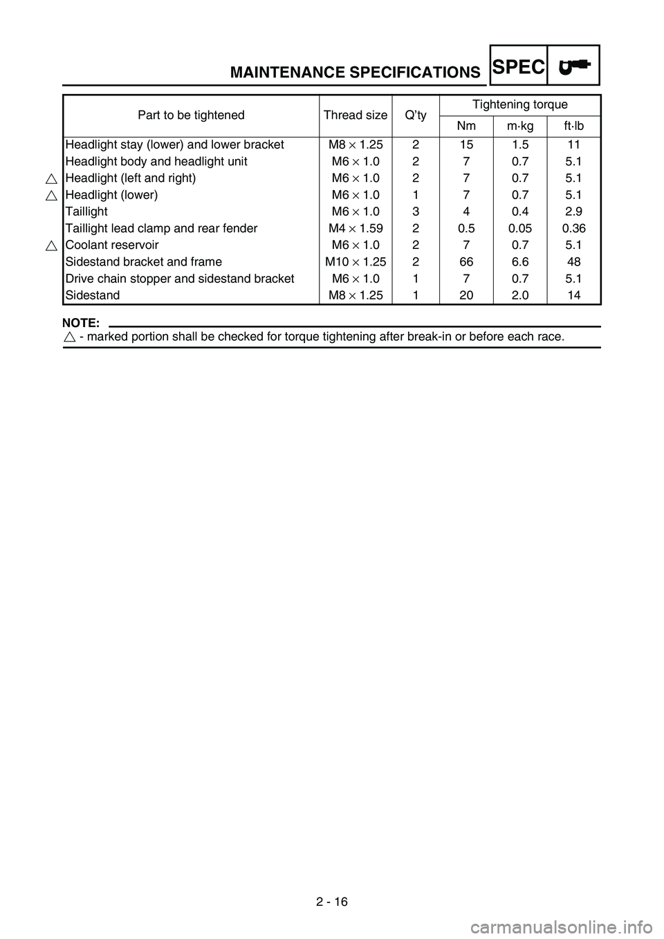
NOTE:
- marked portion shall be checked for torque tightening after break-in or before each race. Headlight stay (lower) and lower bracket M8 × 1.25 2 15 1.5 11
Headlight body and headlight unit M6 × 1.0 2 7 0.7 5.1
Headlight (left and right) M6 × 1.0 2 7 0.7 5.1
Headlight (lower) M6 × 1.0 1 7 0.7 5.1
Taillight M6 × 1.0 3 4 0.4 2.9
Taillight lead clamp and rear fender M4 × 1.59 2 0.5 0.05 0.36
Coolant reservoir M6 × 1.0 2 7 0.7 5.1
Sidestand bracket and frame M10 × 1.25 2 66 6.6 48
Drive chain stopper and sidestand bracket M6 × 1.0 1 7 0.7 5.1
Sidestand M8 × 1.25 1 20 2.0 14 Part to be tightened Thread size Q’tyTightening torque
Nm m·kg ft·lb
Page 176 of 864
SPEC
2 - 97
CABLE ROUTING DIAGRAM
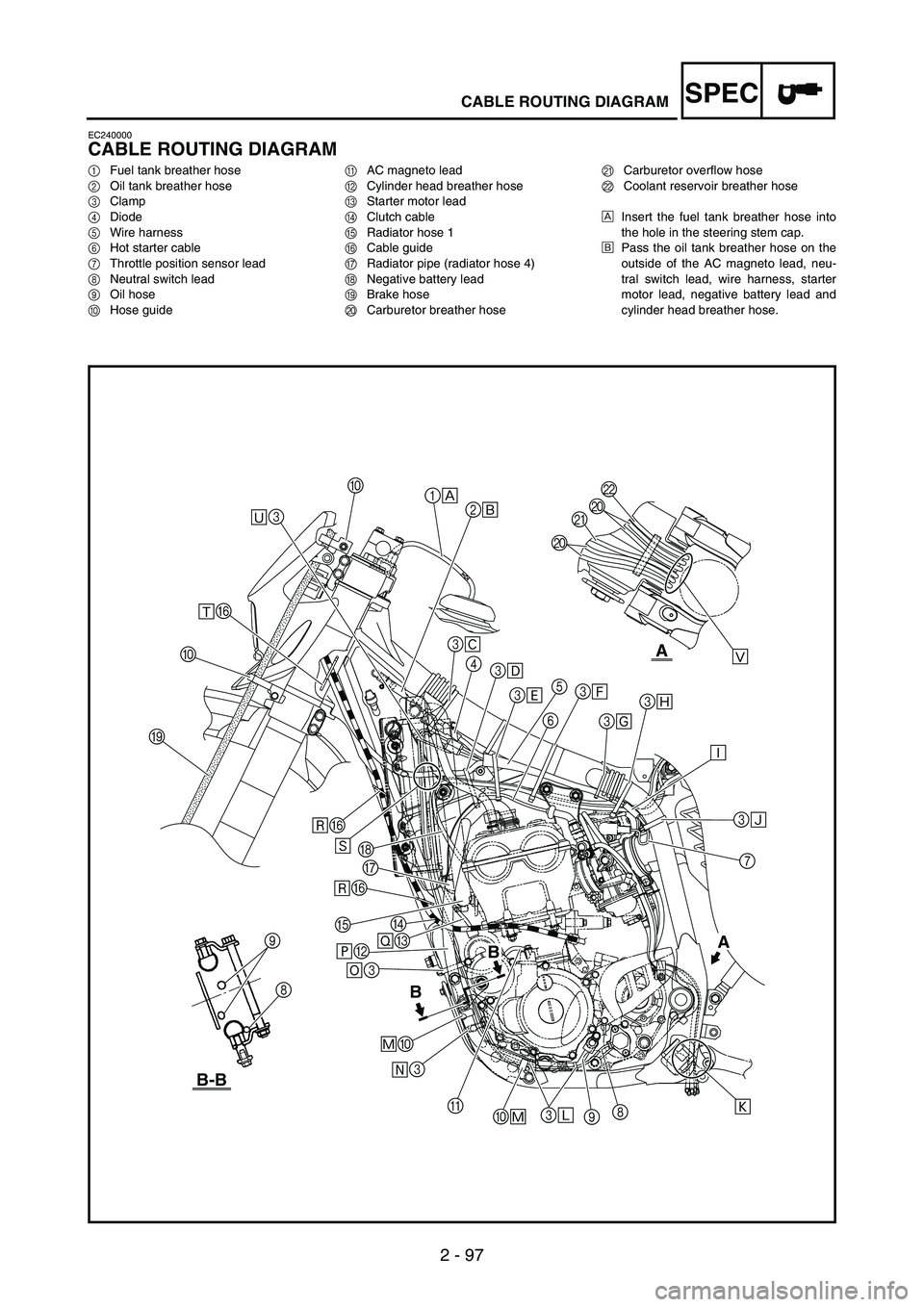
EC240000
CABLE ROUTING DIAGRAM
1Fuel tank breather hose
2Oil tank breather hose
3Clamp
4Diode
5Wire harness
6Hot starter cable
7Throttle position sensor lead
8Neutral switch lead
9Oil hose
0Hose guideAAC magneto lead
BCylinder head breather hose
CStarter motor lead
DClutch cable
ERadiator hose 1
FCable guide
GRadiator pipe (radiator hose 4)
HNegative battery lead
IBrake hose
JCarburetor breather hoseKCarburetor overflow hose
LCoolant reservoir breather hose
ÈInsert the fuel tank breather hose into
the hole in the steering stem cap.
ÉPass the oil tank breather hose on the
outside of the AC magneto lead, neu-
tral switch lead, wire harness, starter
motor lead, negative battery lead and
cylinder head breather hose.
B
BA
B-B
A
Ö3 ×BØC
Ô0
Õ3 G
D
EH
ÙF ÙF
I0ÛF
Ü30
1
È
3
Ê
4
3
Ë
3
Ì5
63
Í
3
Î3
Ï
Ð
Ò Ú3
Ñ
7
9 3
Ó 0
ÔÝ JJ
KL
8 A2
É
9
8
Page 178 of 864
SPEC
2 - 99
CABLE ROUTING DIAGRAM
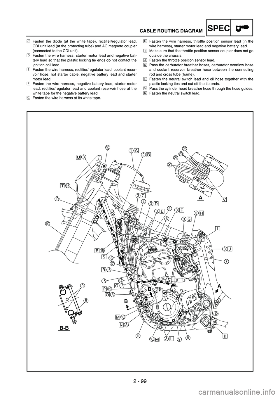
ÊFasten the diode (at the white tape), rectifier/regulator lead,
CDI unit lead (at the protecting tube) and AC magneto coupler
(connected to the CDI unit).
ËFasten the wire harness, starter motor lead and negative bat-
tery lead so that the plastic locking tie ends do not contact the
ignition coil lead.
ÌFasten the wire harness, rectifier/regulator lead, coolant reser-
voir hose, hot starter cable, negative battery lead and starter
motor lead.
ÍFasten the wire harness, negative battery lead, starter motor
lead, rectifier/regulator lead and coolant reservoir hose at the
white tape for the negative battery lead.
ÎFasten the wire harness at its white tape.ÏFasten the wire harness, throttle position sensor lead (in the
wire harness), starter motor lead and negative battery lead.
ÐMake sure that the throttle position sensor coupler does not go
outside the chassis.
ÑFasten the throttle position sensor lead.
ÒPass the carburetor breather hoses, carburetor overflow hose
and coolant reservoir breather hose between the connecting
rod and cross tube (frame).
ÓFasten the neutral switch lead and oil hose together with the
plastic locking ties and cut off the tie ends.
ÔPass the cylinder head breather hose through the hose guides.
ÕFasten the neutral switch lead.
B
BA
B-B
A
Ö3 ×BØC
Ô0
Õ3 G
D
EH
ÙF ÙF
I0ÛF
Ü30
1
È
3
Ê
4
3
Ë
3
Ì5
63
Í
3
Î3
Ï
Ð
Ò Ú3
Ñ
7
9 3
Ó 0
ÔÝ JJ
KL
8 A2
É
9
8
Page 180 of 864
SPEC
2 - 101
CABLE ROUTING DIAGRAM
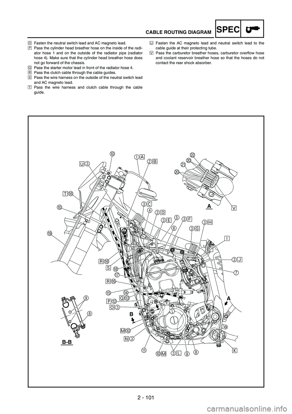
ÖFasten the neutral switch lead and AC magneto lead.
×Pass the cylinder head breather hose on the inside of the radi-
ator hose 1 and on the outside of the radiator pipe (radiator
hose 4). Make sure that the cylinder head breather hose does
not go forward of the chassis.
ØPass the starter motor lead in front of the radiator hose 4.
ÙPass the clutch cable through the cable guides.
ÚPass the wire harness on the outside of the neutral switch lead
and AC magneto lead.
ÛPass the wire harness and clutch cable through the cable
guide.ÜFasten the AC magneto lead and neutral switch lead to the
cable guide at their protecting tube.
ÝPass the carburetor breather hoses, carburetor overflow hose
and coolant reservoir breather hose so that the hoses do not
contact the rear shock absorber.
B
BA
B-B
A
Ö3 ×BØC
Ô0
Õ3 G
D
EH
ÙF ÙF
I0ÛF
Ü30
1
È
3
Ê
4
3
Ë
3
Ì5
63
Í
3
Î3
Ï
Ð
Ò Ú3
Ñ
7
9 3
Ó 0
ÔÝ JJ
KL
8 A2
É
9
8
Page 182 of 864
SPEC
2 - 103
CABLE ROUTING DIAGRAM
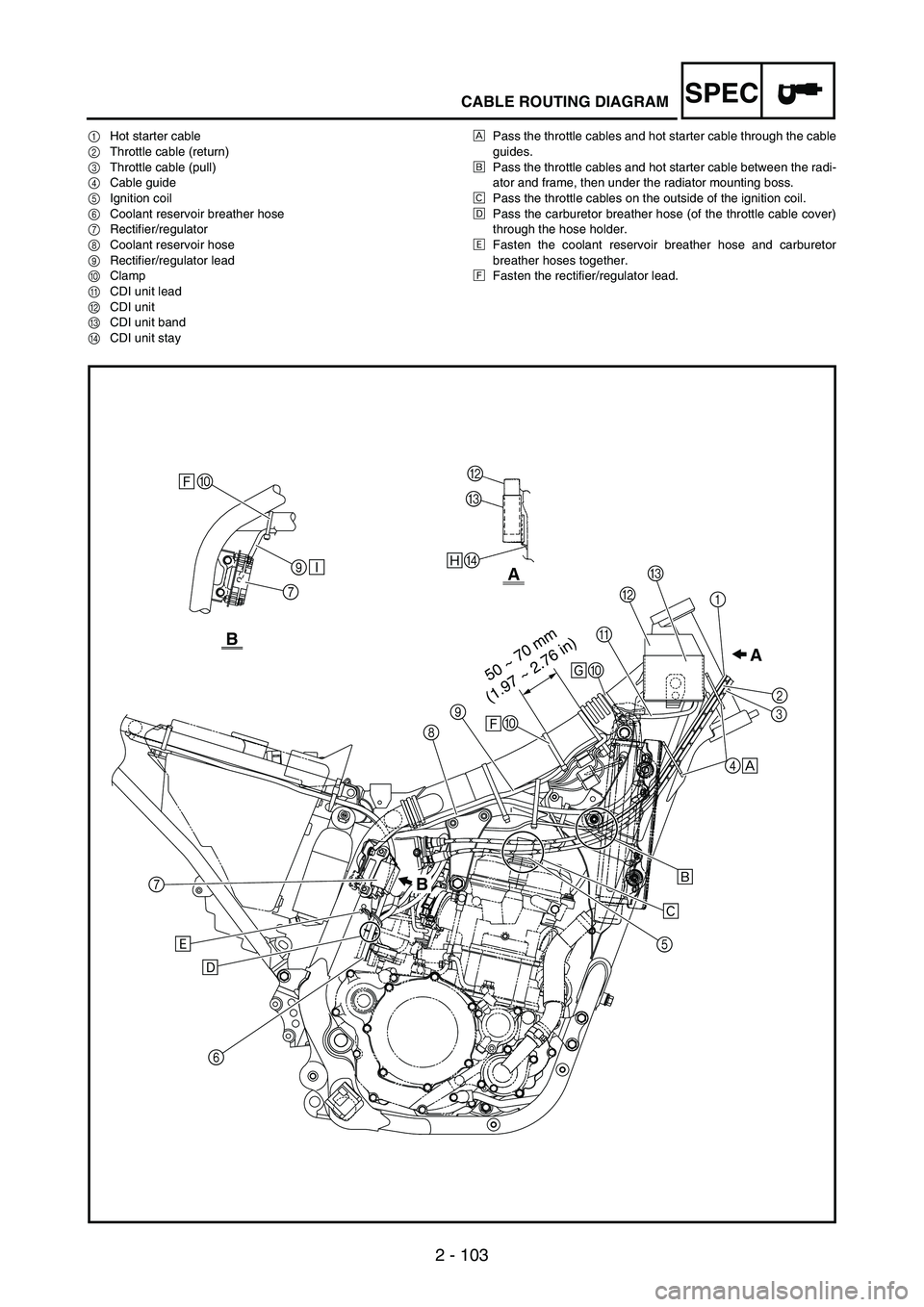
1Hot starter cable
2Throttle cable (return)
3Throttle cable (pull)
4Cable guide
5Ignition coil
6Coolant reservoir breather hose
7Rectifier/regulator
8Coolant reservoir hose
9Rectifier/regulator lead
0Clamp
ACDI unit lead
BCDI unit
CCDI unit band
DCDI unit stayÈPass the throttle cables and hot starter cable through the cable
guides.
ÉPass the throttle cables and hot starter cable between the radi-
ator and frame, then under the radiator mounting boss.
ÊPass the throttle cables on the outside of the ignition coil.
ËPass the carburetor breather hose (of the throttle cable cover)
through the hose holder.
ÌFasten the coolant reservoir breather hose and carburetor
breather hoses together.
ÍFasten the rectifier/regulator lead.
50 ~ 70 mm
(1.97 ~ 2.76 in)
A ÏD
B
B
B
C
8
Î0
Í0A
9BC
1
32
4
È
É
Ê
5
6 7
Ë Ì
0
79
Ð Í
Page 188 of 864
SPEC
2 - 109
CABLE ROUTING DIAGRAM
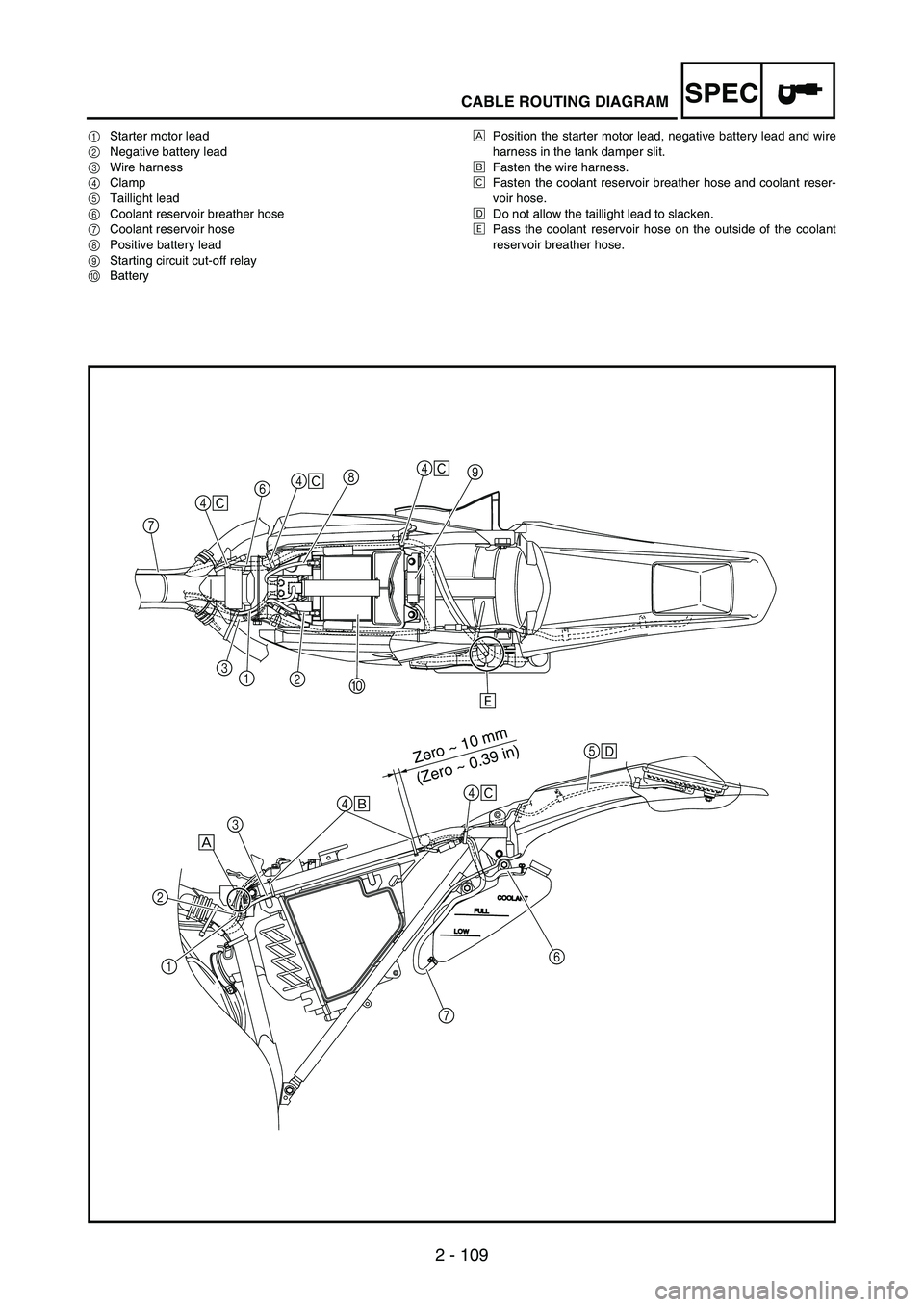
1Starter motor lead
2Negative battery lead
3Wire harness
4Clamp
5Taillight lead
6Coolant reservoir breather hose
7Coolant reservoir hose
8Positive battery lead
9Starting circuit cut-off relay
0BatteryÈPosition the starter motor lead, negative battery lead and wire
harness in the tank damper slit.
ÉFasten the wire harness.
ÊFasten the coolant reservoir breather hose and coolant reser-
voir hose.
ËDo not allow the taillight lead to slacken.
ÌPass the coolant reservoir hose on the outside of the coolant
reservoir breather hose.
Zero ~ 10 mm
(Zero ~ 0.39 in)
9
0 1
2 368
Ì 4
Ê
74
Ê4
Ê
4
Ê
5
Ë
4
É
3
È
1 2
6
7