light YAMAHA WR 250F 2006 Owner's Guide
[x] Cancel search | Manufacturer: YAMAHA, Model Year: 2006, Model line: WR 250F, Model: YAMAHA WR 250F 2006Pages: 900, PDF Size: 23.77 MB
Page 446 of 900
4 - 105
ENGVALVES AND VALVE SPRINGS
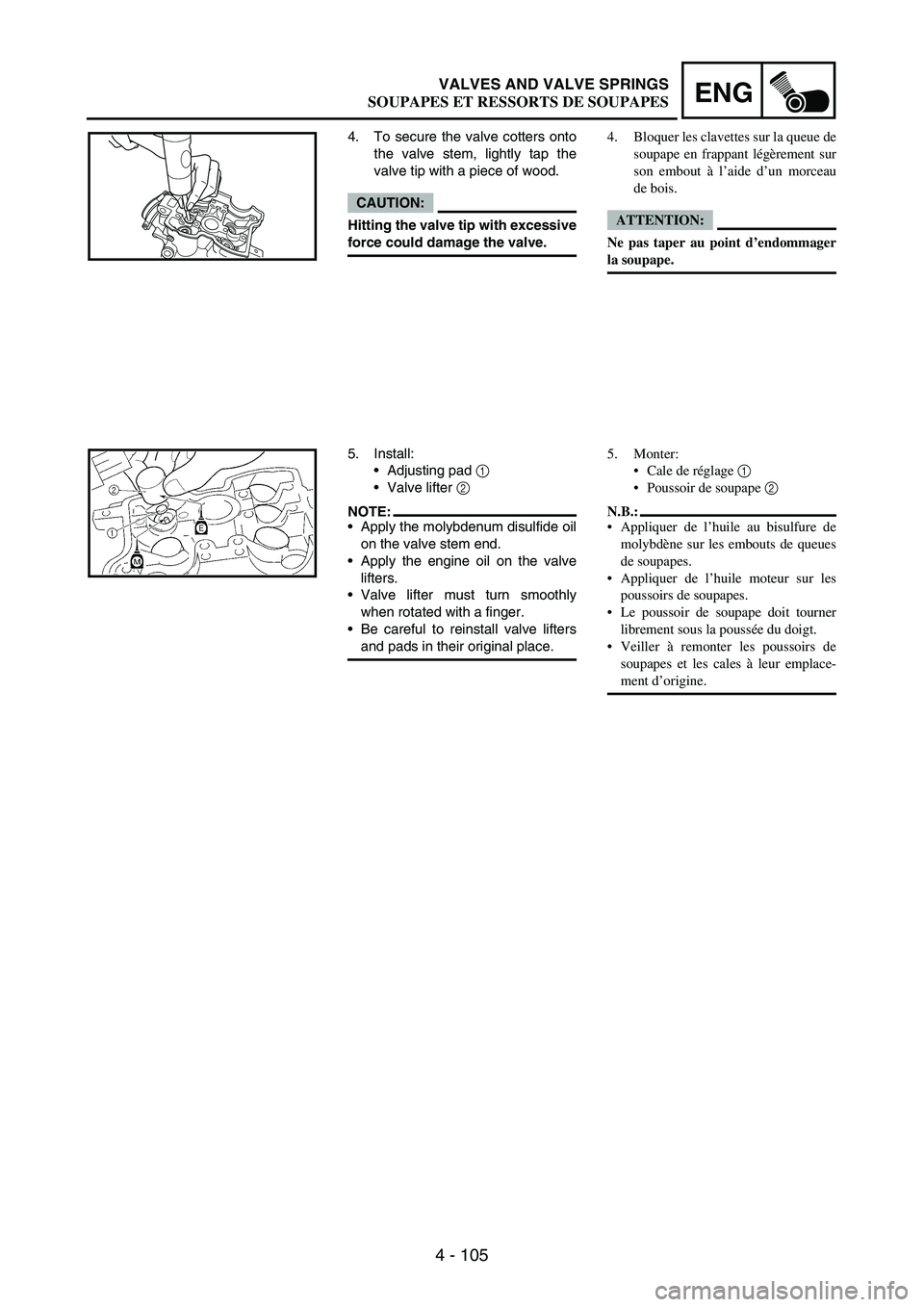
4. To secure the valve cotters onto
the valve stem, lightly tap the
valve tip with a piece of wood.
CAUTION:
Hitting the valve tip with excessive
force could damage the valve.
5. Install:
Adjusting pad
1
Valve lifter
2
NOTE:Apply the molybdenum disulfide oil
on the valve stem end.
Apply the engine oil on the valve
lifters.
Valve lifter must turn smoothly
when rotated with a finger.
Be careful to reinstall valve lifters
and pads in their original place.
4. Bloquer les clavettes sur la queue de
soupape en frappant légèrement sur
son embout à l’aide d’un morceau
de bois.
ATTENTION:
Ne pas taper au point d’endommager
la soupape.
5. Monter:
Cale de réglage 1
Poussoir de soupape 2
N.B.:
Appliquer de l’huile au bisulfure de
molybdène sur les embouts de queues
de soupapes.
Appliquer de l’huile moteur sur les
poussoirs de soupapes.
Le poussoir de soupape doit tourner
librement sous la poussée du doigt.
Veiller à remonter les poussoirs de
soupapes et les cales à leur emplace-
ment d’origine.
SOUPAPES ET RESSORTS DE SOUPAPES
Page 582 of 900

4 - 241
ENGCRANKCASE AND CRANKSHAFT
REMOVAL POINTS
Crankcase
1. Separate:
Right crankcase
Left crankcase
Separation steps:
Remove the crankcase bolts
1,
hose guide
2 and clutch cable
holder
3.
NOTE:Loosen each bolt 1/4 of a turn at a
time and after all the bolts are
loosened, remove them.
Remove the right crankcase
4.
NOTE:Place the crankcase with its left
side downward and split it by
inserting a screwdriver tip into
the splitting slit
a in the crank-
case.
Lift the right crankcase horizon-
tally while lightly patting the
case splitting slit and engine
mounting boss using a soft
hammer, and leave the crank-
shaft and transmission with the
left crankcase.
CAUTION:
Use soft hammer to tap on the
case half. Tap only on rein-
forced portions of case. Do not
tap on gasket mating surface.
Work slowly and carefully.
Make sure the case halves sep-
arate evenly. If one end “hangs
up”, take pressure off the push
screw, realign, and start over. If
the cases do not separate,
check for a remaining case
screw or fitting. Do not force.
Remove the dowel pins and O-
ring.
a
4
POINTS DE DEPOSE
Carter moteur
1. Séparer:
Carter moteur droit
Carter moteur gauche
Etapes de la séparation:
Déposer les boulons du carter
moteur 1, le guide de durit 2 et le
support de câble d’embrayage 3.
N.B.:
Desserrer chaque boulon d’1/4 de
tour à la fois puis, lorsque tous les
boulons sont desserrés, les déposer.
Déposez le carter moteur droit 4.
N.B.:
Placer le côté gauche du carter
moteur vers le bas et séparez-le en
insérant une lame de tournevis
dans la fente de séparation a du
carter moteur.
Soulevez le carter moteur droit
horizontalement tout en tapotant
légèrement la fente de séparation
du carter et la noix de montage du
moteur à l’aide d’un maillet en
caoutchouc; laisser le vilebrequin
et la boîte de vitesses dans le carter
moteur gauche.
ATTENTION:
Taper sur le demi-carter à l’aide
d’un maillet en plastique. Ne taper
que sur les renforcements du car-
ter. Ne pas taper sur la surface de
contact du joint. Travailler lente-
ment et avec précaution. Veiller à
séparer les deux demi-carters
symétriquement. Si l’un d’eux
“accroche”, relâcher la pression à
l’aide de la vis-poussoir, réaligner
et recommencer. Si les deux demi-
carters ne se séparent pas, vérifier
qu’une vis ou une fixation n’ont
pas été oubliées. Ne jamais forcer.
Déposer les goujons et le joint tori-
que.
CARTER MOTEUR ET VILEBREQUIN
Page 590 of 900
4 - 249
ENGCRANKCASE AND CRANKSHAFT
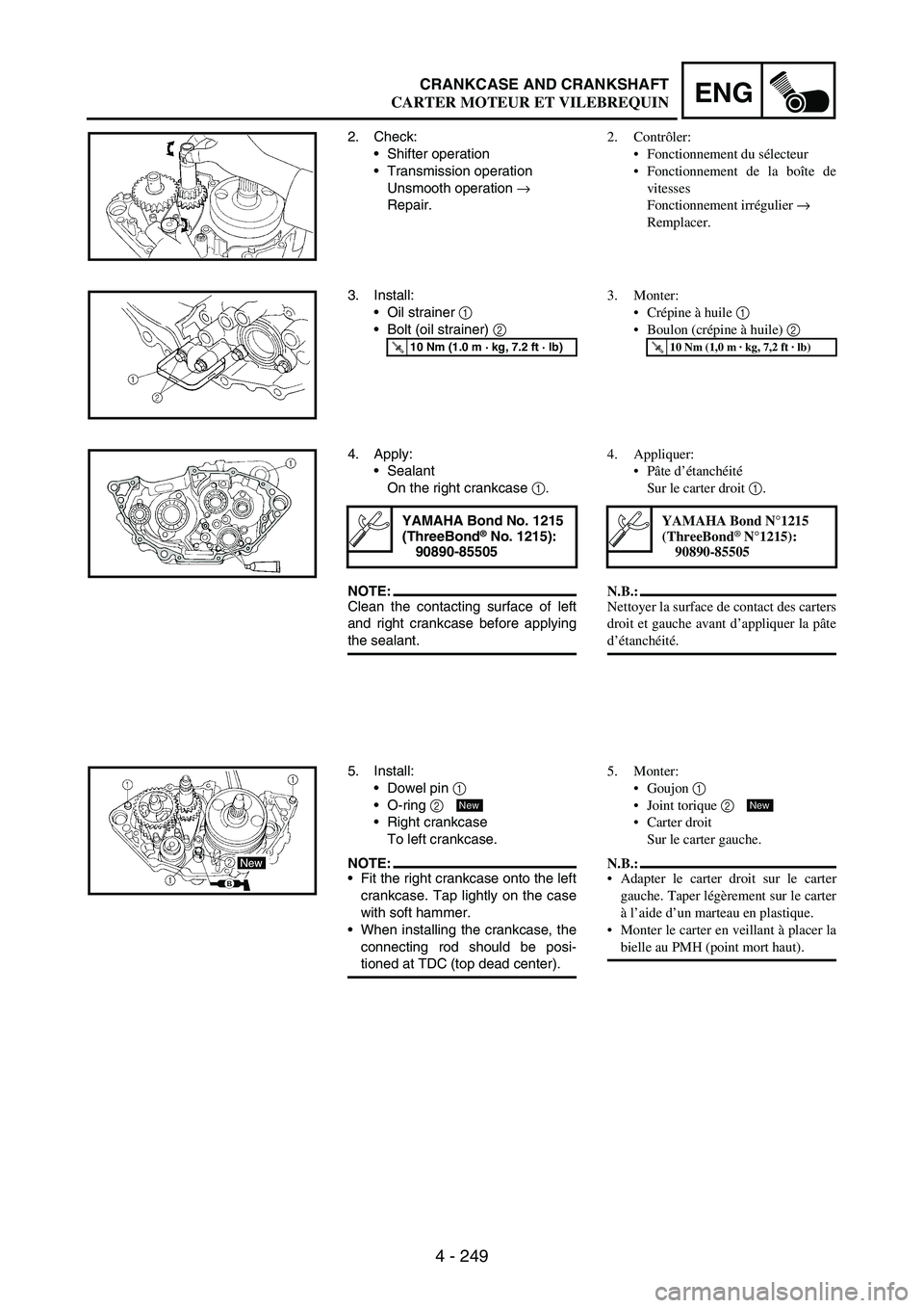
2. Check:
Shifter operation
Transmission operation
Unsmooth operation
→
Repair.
3. Install:
Oil strainer
1
Bolt (oil strainer)
2
T R..10 Nm (1.0 m · kg, 7.2 ft · lb)
4. Apply:
Sealant
On the right crankcase
1.
NOTE:Clean the contacting surface of left
and right crankcase before applying
the sealant.
YAMAHA Bond No. 1215
(ThreeBond® No. 1215):
90890-85505
5. Install:
Dowel pin
1
O-ring
2
Right crankcase
To left crankcase.
NOTE:Fit the right crankcase onto the left
crankcase. Tap lightly on the case
with soft hammer.
When installing the crankcase, the
connecting rod should be posi-
tioned at TDC (top dead center).
New
2. Contrôler:
Fonctionnement du sélecteur
Fonctionnement de la boîte de
vitesses
Fonctionnement irrégulier →
Remplacer.
3. Monter:
Crépine à huile 1
Boulon (crépine à huile) 2
T R..10 Nm (1,0 m · kg, 7,2 ft · lb)
4. Appliquer:
Pâte d’étanchéité
Sur le carter droit 1.
N.B.:
Nettoyer la surface de contact des carters
droit et gauche avant d’appliquer la pâte
d’étanchéité.
YAMAHA Bond N°1215
(ThreeBond® N°1215):
90890-85505
5. Monter:
Goujon 1
Joint torique 2
Carter droit
Sur le carter gauche.
N.B.:
Adapter le carter droit sur le carter
gauche. Taper légèrement sur le carter
à l’aide d’un marteau en plastique.
Monter le carter en veillant à placer la
bielle au PMH (point mort haut).
New
CARTER MOTEUR ET VILEBREQUIN
Page 598 of 900
4 - 257
ENGTRANSMISSION, SHIFT CAM AND SHIFT FORK
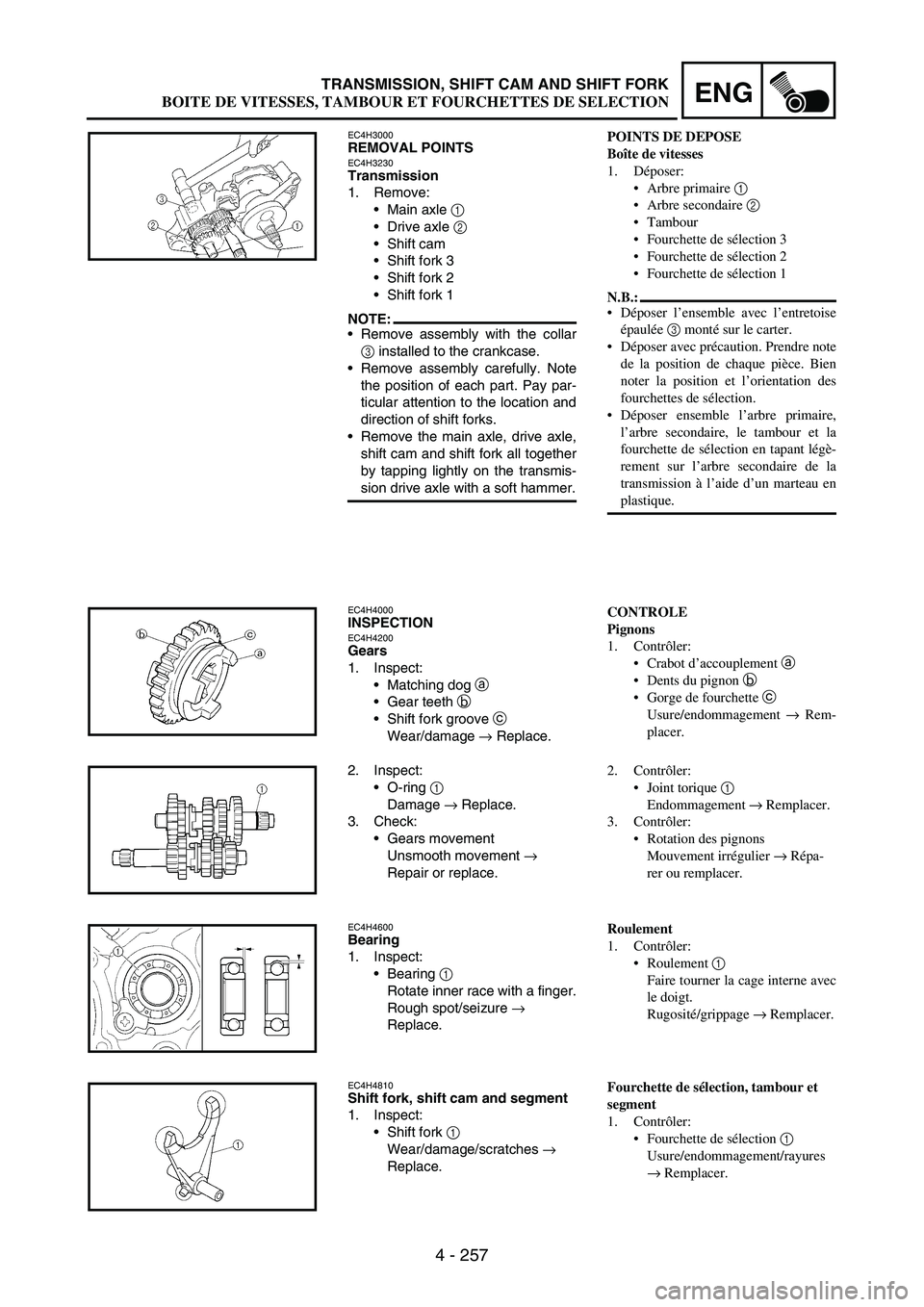
EC4H3000REMOVAL POINTSEC4H3230Transmission
1. Remove:
Main axle
1
Drive axle
2
Shift cam
Shift fork 3
Shift fork 2
Shift fork 1
NOTE:Remove assembly with the collar
3 installed to the crankcase.
Remove assembly carefully. Note
the position of each part. Pay par-
ticular attention to the location and
direction of shift forks.
Remove the main axle, drive axle,
shift cam and shift fork all together
by tapping lightly on the transmis-
sion drive axle with a soft hammer.
EC4H4000INSPECTIONEC4H4200Gears
1. Inspect:
Matching dog
a
Gear teeth
b
Shift fork groove
c
Wear/damage
→ Replace.
2. Inspect:
O-ring
1
Damage
→ Replace.
3. Check:
Gears movement
Unsmooth movement
→
Repair or replace.
EC4H4600Bearing
1. Inspect:
Bearing
1
Rotate inner race with a finger.
Rough spot/seizure
→
Replace.
EC4H4810Shift fork, shift cam and segment
1. Inspect:
Shift fork
1
Wear/damage/scratches
→
Replace.
POINTS DE DEPOSE
Boîte de vitesses
1. Déposer:
Arbre primaire 1
Arbre secondaire 2
Tambour
Fourchette de sélection 3
Fourchette de sélection 2
Fourchette de sélection 1
N.B.:
Déposer l’ensemble avec l’entretoise
épaulée 3 monté sur le carter.
Déposer avec précaution. Prendre note
de la position de chaque pièce. Bien
noter la position et l’orientation des
fourchettes de sélection.
Déposer ensemble l’arbre primaire,
l’arbre secondaire, le tambour et la
fourchette de sélection en tapant légè-
rement sur l’arbre secondaire de la
transmission à l’aide d’un marteau en
plastique.
CONTROLE
Pignons
1. Contrôler:
Crabot d’accouplement a
Dents du pignon b
Gorge de fourchette c
Usure/endommagement → Rem-
placer.
2. Contrôler:
Joint torique 1
Endommagement → Remplacer.
3. Contrôler:
Rotation des pignons
Mouvement irrégulier → Répa-
rer ou remplacer.
Roulement
1. Contrôler:
Roulement 1
Faire tourner la cage interne avec
le doigt.
Rugosité/grippage → Remplacer.
Fourchette de sélection, tambour et
segment
1. Contrôler:
Fourchette de sélection 1
Usure/endommagement/rayures
→ Remplacer.
BOITE DE VITESSES, TAMBOUR ET FOURCHETTES DE SELECTION
Page 656 of 900
5 - 51
CHASFRONT BRAKE AND REAR BRAKE
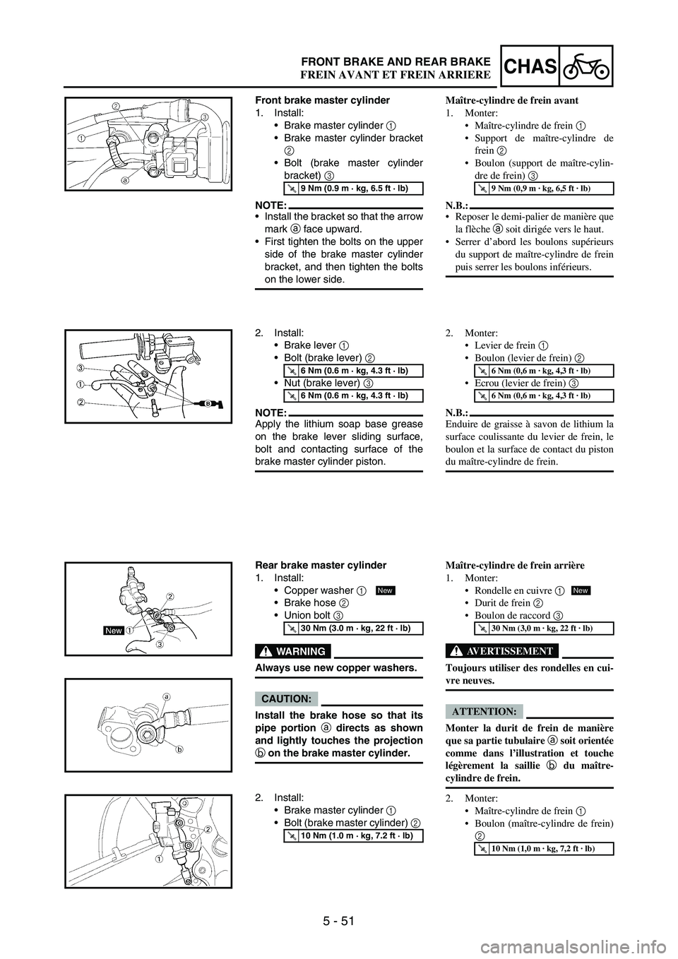
Front brake master cylinder
1. Install:
Brake master cylinder
1
Brake master cylinder bracket
2
Bolt (brake master cylinder
bracket)
3
NOTE:Install the bracket so that the arrow
mark
a face upward.
First tighten the bolts on the upper
side of the brake master cylinder
bracket, and then tighten the bolts
on the lower side.
T R..9 Nm (0.9 m · kg, 6.5 ft · lb)
2. Install:
Brake lever
1
Bolt (brake lever)
2
Nut (brake lever)
3
NOTE:Apply the lithium soap base grease
on the brake lever sliding surface,
bolt and contacting surface of the
brake master cylinder piston.
T R..6 Nm (0.6 m · kg, 4.3 ft · lb)
T R..6 Nm (0.6 m · kg, 4.3 ft · lb)
Rear brake master cylinder
1. Install:
Copper washer
1
Brake hose
2
Union bolt
3
WARNING
Always use new copper washers.
CAUTION:
Install the brake hose so that its
pipe portion a
directs as shown
and lightly touches the projection
b
on the brake master cylinder.
T R..30 Nm (3.0 m · kg, 22 ft · lb)
New
2. Install:
Brake master cylinder
1
Bolt (brake master cylinder)
2
T R..10 Nm (1.0 m · kg, 7.2 ft · lb)
Maître-cylindre de frein avant
1. Monter:
Maître-cylindre de frein 1
Support de maître-cylindre de
frein 2
Boulon (support de maître-cylin-
dre de frein) 3
N.B.:
Reposer le demi-palier de manière que
la flèche a soit dirigée vers le haut.
Serrer d’abord les boulons supérieurs
du support de maître-cylindre de frein
puis serrer les boulons inférieurs.
T R..9 Nm (0,9 m · kg, 6,5 ft · lb)
2. Monter:
Levier de frein 1
Boulon (levier de frein) 2
Ecrou (levier de frein) 3
N.B.:
Enduire de graisse à savon de lithium la
surface coulissante du levier de frein, le
boulon et la surface de contact du piston
du maître-cylindre de frein.
T R..6 Nm (0,6 m · kg, 4,3 ft · lb)
T R..6 Nm (0,6 m · kg, 4,3 ft · lb)
Maître-cylindre de frein arrière
1. Monter:
Rondelle en cuivre 1
Durit de frein 2
Boulon de raccord 3
AVERTISSEMENT
Toujours utiliser des rondelles en cui-
vre neuves.
ATTENTION:
Monter la durit de frein de manière
que sa partie tubulaire a soit orientée
comme dans l’illustration et touche
légèrement la saillie b du maître-
cylindre de frein.
2. Monter:
Maître-cylindre de frein 1
Boulon (maître-cylindre de frein)
2
T R..30 Nm (3,0 m · kg, 22 ft · lb)
T R..10 Nm (1,0 m · kg, 7,2 ft · lb)
New
FREIN AVANT ET FREIN ARRIERE
Page 658 of 900
5 - 53
CHASFRONT BRAKE AND REAR BRAKE
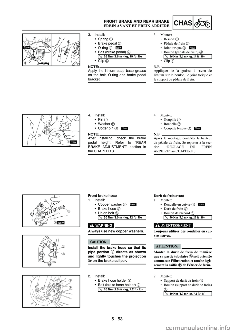
3. Install:
Spring
1
Brake pedal
2
O-ring
3
Bolt (brake pedal)
4
Clip
5
NOTE:Apply the lithium soap base grease
on the bolt, O-ring and brake pedal
bracket.
T R..26 Nm (2.6 m · kg, 19 ft · lb)
New
4. Install:
Pin
1
Washer
2
Cotter pin
3
NOTE:After installing, check the brake
pedal height. Refer to “REAR
BRAKE ADJUSTMENT” section in
the CHAPTER 3.
New
Front brake hose
1. Install:
Copper washer
1
Brake hose
2
Union bolt
3
WARNING
Always use new copper washers.
CAUTION:
Install the brake hose so that its
pipe portion a
directs as shown
and lightly touches the projection
b
on the brake caliper.
T R..30 Nm (3.0 m · kg, 22 ft · lb)
New
2. Install:
Brake hose holder
1
Bolt (brake hose holder)
2
T R..10 Nm (1.0 m · kg, 7.2 ft · lb)
3. Monter:
Ressort 1
Pédale de frein 2
Joint torique 3
Boulon (pédale de frein) 4
Clip 5
N.B.:
Appliquer de la graisse à savon de
lithium sur le boulon, le joint torique et
le support de pédale de frein.
T R..26 Nm (2,6 m · kg, 19 ft · lb)
New
4. Monter:
Goupille 1
Rondelle 2
Goupille fendue 3
N.B.:
Après le montage, contrôler la hauteur
de pédale de frein. Se reporter à la sec-
tion “REGLAGE DU FREIN
ARRIERE” au CHAPITRE 3.
New
Durit de frein avant
1. Monter:
Rondelle en cuivre 1
Durit de frein 2
Boulon de raccord 3
AVERTISSEMENT
Toujours utiliser des rondelles en cui-
vre neuves.
ATTENTION:
Monter la durit de frein de manière
que sa partie tubulaire a soit orientée
comme sur l’illustration et touche légè-
rement la saillie b de l’étrier de frein.
T R..30 Nm (3,0 m · kg, 22 ft · lb)
New
2. Monter:
Support de durit de frein 1
Boulon (support de durit de frein)
2
T R..10 Nm (1,0 m · kg, 7,2 ft · lb)
FREIN AVANT ET FREIN ARRIERE
Page 660 of 900
5 - 55
CHASFRONT BRAKE AND REAR BRAKE
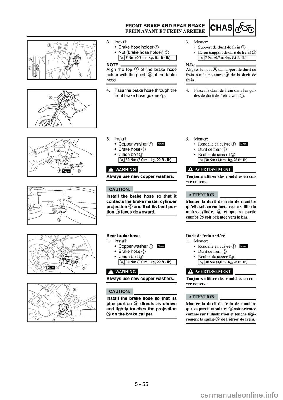
3. Install:
Brake hose holder
1
Nut (brake hose holder)
2
NOTE:Align the top
a of the brake hose
holder with the paint
b of the brake
hose.
T R..7 Nm (0.7 m · kg, 5.1 ft · lb)
4. Pass the brake hose through the
front brake hose guides
1.
5. Install:
Copper washer
1
Brake hose
2
Union bolt
3
WARNING
Always use new copper washers.
CAUTION:
Install the brake hose so that it
contacts the brake master cylinder
projection a
and that its bent por-
tion b
faces downward.
T R..30 Nm (3.0 m · kg, 22 ft · lb)
New
Rear brake hose
1. Install:
Copper washer
1
Brake hose
2
Union bolt
3
WARNING
Always use new copper washers.
CAUTION:
Install the brake hose so that its
pipe portion a
directs as shown
and lightly touches the projection
b
on the brake caliper.
T R..30 Nm (3.0 m · kg, 22 ft · lb)
New
3. Monter:
Support de durit de frein 1
Ecrou (support de durit de frein) 2
N.B.:
Aligner le haut a du support de durit de
frein sur la peinture b de la durit de
frein.
T R..7 Nm (0,7 m · kg, 5,1 ft · lb)
4. Passer la durit de frein dans les gui-
des de durit de frein avant 1.
5. Monter:
Rondelle en cuivre 1
Durit de frein 2
Boulon de raccord 3
AVERTISSEMENT
Toujours utiliser des rondelles en cui-
vre neuves.
ATTENTION:
Monter la durit de frein de manière
qu’elle soit en contact avec la saillie du
maître-cylindre a et que sa partie
courbe b soit orientée vers le bas.
T R..30 Nm (3,0 m · kg, 22 ft · lb)
New
Durit de frein arrière
1. Monter:
Rondelle en cuivre 1
Durit de frein 2
Boulon de raccord3
AVERTISSEMENT
Toujours utiliser des rondelles en cui-
vre neuves.
ATTENTION:
Monter la durit de frein de manière
que sa partie tubulaire a soit orientée
comme sur l’illustration et touche légè-
rement la saillie b de l’étrier de frein.
T R..30 Nm (3,0 m · kg, 22 ft · lb)
New
FREIN AVANT ET FREIN ARRIERE
Page 666 of 900
5 - 61
CHASFRONT FORK
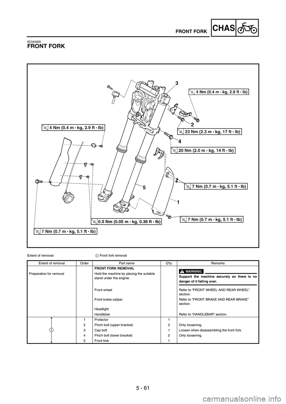
EC550000
FRONT FORK
Extent of removal:
1 Front fork removal
Extent of removal Order Part name Q’ty Remarks
FRONT FORK REMOVAL
WARNING
Support the machine securely so there is nodanger of it falling over. Preparation for removal Hold the machine by placing the suitable
stand under the engine.
Front wheel Refer to “FRONT WHEEL AND REAR WHEEL”
section.
Front brake caliper Refer to “FRONT BRAKE AND REAR BRAKE”
section.
Headlight
Handlebar Refer to “HANDLEBAR” section.
1 Protector 1
2 Pinch bolt (upper bracket) 2 Only loosening.
3 Cap bolt 1 Loosen when disassembling the front fork.
4 Pinch bolt (lower bracket) 2 Only loosening.
5 Front fork 1
1
Page 696 of 900
5 - 91
CHASHANDLEBAR
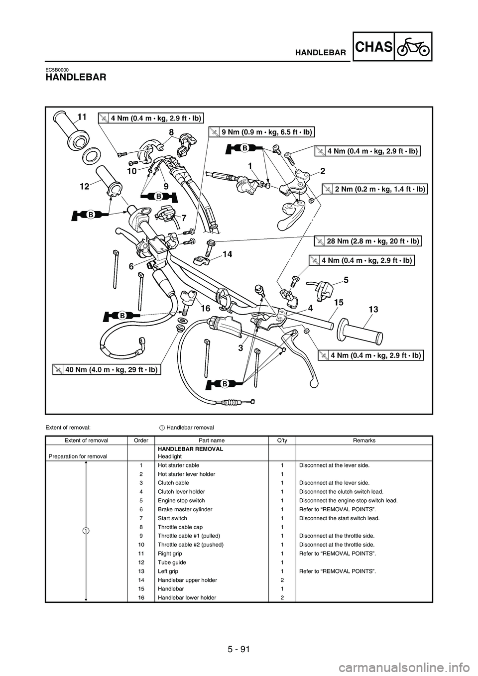
EC5B0000
HANDLEBAR
Extent of removal:
1 Handlebar removal
Extent of removal Order Part name Q’ty Remarks
Preparation for removalHANDLEBAR REMOVAL
Headlight
1 Hot starter cable 1 Disconnect at the lever side.
2 Hot starter lever holder 1
3 Clutch cable 1 Disconnect at the lever side.
4 Clutch lever holder 1 Disconnect the clutch switch lead.
5 Engine stop switch 1 Disconnect the engine stop switch lead.
6 Brake master cylinder 1 Refer to “REMOVAL POINTS”.
7 Start switch 1 Disconnect the start switch lead.
8 Throttle cable cap 1
9 Throttle cable #1 (pulled) 1 Disconnect at the throttle side.
10 Throttle cable #2 (pushed) 1 Disconnect at the throttle side.
11 Right grip 1 Refer to “REMOVAL POINTS”.
12 Tube guide 1
13 Left grip 1 Refer to “REMOVAL POINTS”.
14 Handlebar upper holder 2
15 Handlebar 1
16 Handlebar lower holder 2
1
Page 710 of 900
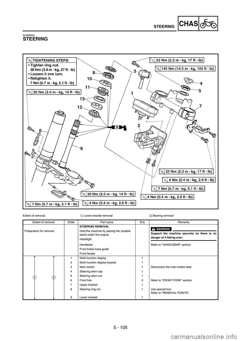
5 - 105
CHASSTEERING
EC560000
STEERING
Extent of removal:
1 Lower bracket removal
2 Bearing removal
Extent of removal Order Part name Q’ty Remarks
STEERING REMOVAL
WARNING
Support the machine securely so there is nodanger of it falling over. Preparation for removal Hold the machine by placing the suitable
stand under the engine.
Headlight
Handlebar Refer to “HANDLEBAR” section.
Front brake hose guide
Front fender
1 Multi-function display 1
2 Multi-function display bracket 1
3 Main switch 1 Disconnect the main switch lead.
4 Steering stem cap 1
5 Steering stem nut 1
6 Front fork 2 Refer to “FRONT FORK” section.
7 Upper bracket 1
8 Steering ring nut 1 Use special tool.
Refer to “REMOVAL POINTS”.
9 Lower bracket 1
12