length YAMAHA WR 250F 2006 Owners Manual
[x] Cancel search | Manufacturer: YAMAHA, Model Year: 2006, Model line: WR 250F, Model: YAMAHA WR 250F 2006Pages: 900, PDF Size: 23.77 MB
Page 8 of 900
6. GASOLINE CAN CAUSE
INJURY.
If you should swallow some
gasoline, inhale excess
gasoline vapors, or allow
any gasoline to get into
your eyes, contact a doctor
immediately. If any gaso-
line spills onto your skin or
clothing, immediately wash
skin areas with soap and
water, and change your
clothes.
7. ONLY OPERATE THE
MACHINE IN AN AREA
WITH ADEQUATE VENTI-
LATION.
Never start the engine or let
it run for any length of time
in an enclosed area.
Exhaust fumes are poison-
ous. These fumes contain
carbon monoxide, which by
itself is odorless and color-
less. Carbon monoxide is a
dangerous gas which can
cause unconsciousness or
can be lethal.
8. PARK THE MACHINE
CAREFULLY; TURN OFF
THE ENGINE.
Always turn off the engine
if you are going to leave the
machine. Do not park the
machine on a slope or soft
ground as it may fall over.
9. THE ENGINE, EXHAUST
PIPE, MUFFLER, AND OIL
TANK WILL BE VERY HOT
AFTER THE ENGINE HAS
BEEN RUN.
Be careful not to touch
them or to allow any cloth-
ing item to contact them
during inspection or repair.
10. PROPERLY SECURE THE
MACHINE BEFORE TRANS-
PORTING IT.
When transporting the
machine in another vehicle,
always be sure it is prop-
erly secured and in an
upright position and that
the fuel cock is in the
“OFF” position. Otherwise,
fuel may leak out of the car-
buretor or fuel tank.6. L’ESSENCE PEUT CAUSER
DES BLESSURES.
Si vous avalez de l’essence, res-
pirez des vapeurs d’essence en
excès ou laissez de l’essence
pénétrer dans vos yeux, pren-
dre immédiatement contact
avec un médecin. Si de
l’essence est renversée sur
votre peau ou vos vêtements,
laver immédiatement la peau
avec du savon et de l’eau et
changer de vêtements.
7. N’UTILISER LA MACHINE
QUE DANS UN ENDROIT
AVEC AERATION ADE-
QUATE.
Ne jamais mettre le moteur en
marche ni le laisser tourner
pendant un quelconque laps de
temps dans un endroit clos.
Les fumées d’échappement
sont toxiques. Ces fumées con-
tiennent du monoxyde de car-
bone incolore et inodore. Le
monoxyde de carbone est un
gaz toxique dangereux qui
peut entraîner la perte de con-
naissance ou être mortel.
8. STATIONNER AVEC SOIN
LA MACHINE ET ARRE-
TER LE MOTEUR.
Toujours arrêter le moteur si
vous devez abandonner la
machine. Ne pas stationner en
pente ou sur un sol mou ou elle
pourrait se renverser.
9. LE MOTEUR, LE SYSTÈME
D’ÉCHAPPEMENT ET LE
RÉSERVOIR D’HUILE
SONT TRÈS CHAUDS
LORSQUE LE MOTEUR A
TOURNÉ.
Bien veiller à ne pas toucher
ces organes et éviter tout con-
tact avec les vêtements pen-
dant l’inspection ou la
réparation du véhicule.
10. FIXER SOLIDEMENT LA
MACHINE AVANT DE LA
TRANSPORTER.
En cas de transport de la
machine sur un autre véhicule,
toujours s’assurer qu’elle est
correctement fixée et posée sur
ses roues et que le robinet de
carburant est dans la position
OFF (fermé). Sans quoi il peut
y avoir des fuites du carbura-
teur et du réservoir.
Page 94 of 900

GENERAL SPECIFICATIONS
2 - 1
SPEC
EC200000
SPECIFICATIONS
EC211000
GENERAL SPECIFICATIONS
Model name: WR250FV (USA, CDN, AUS, NZ)
WR250F (EUROPE, ZA)
Model code number: 5UMB (USA)
5UMC (EUROPE)
5UMD (CDN, AUS, NZ, ZA)
Dimensions: USA, ZA, CDN EUROPE, AUS, NZ
Overall length 2,190 mm (86.22 in) 2,180 mm (85.83 in)
Overall width 830 mm (32.68 in)←
Overall height 1,290 mm (50.79 in) 1,295 mm (50.98 in)
Seat height 985 mm (38.78 in) 990 mm (38.98 in)
Wheelbase 1,470 mm (57.87 in)←
Minimum ground clearance 370 mm (14.57 in) 375 mm (14.76 in)
Dry weight:
Without oil and fuel 106.5 kg (234.8 lb)
Engine:
Engine type Liquid cooled 4-stroke, DOHC
Cylinder arrangement Single cylinder, forward inclined
Displacement 249 cm
3 (8.76 Imp oz, 8.42 US oz)
Bore × stroke 77.0 × 53.6 mm (3.03 × 2.11 in)
Compression ratio 12.5 : 1
Kick and electric starter
Starting system
Lubrication system: Dry sump
Oil type or grade:
Engine oil (For USA and CDN)
At 5 °C (40 °F) or higher È
Yamalube 4 (20W-40) or SAE 20W-40 type
SG motor oil
(Non-Friction modified)
At 15 °C (60 °F) or lower É
Yamalube 4 (10W-30) or SAE 10W-30 type
SG motor oil
(Non-Friction modified)
and/or
Yamalube 4-R (15W-50)
(Non-Friction modified)
(Except for USA and CDN)
API “SG” or higher grade
-20
-4-10
140
3010
5020
6830
8640 50
104
122˚CTemp.
˚F
10W-30
10W-40
20W-40
20W-50
15W-40
2
Page 99 of 900
MAINTENANCE SPECIFICATIONS
2 - 6
SPEC
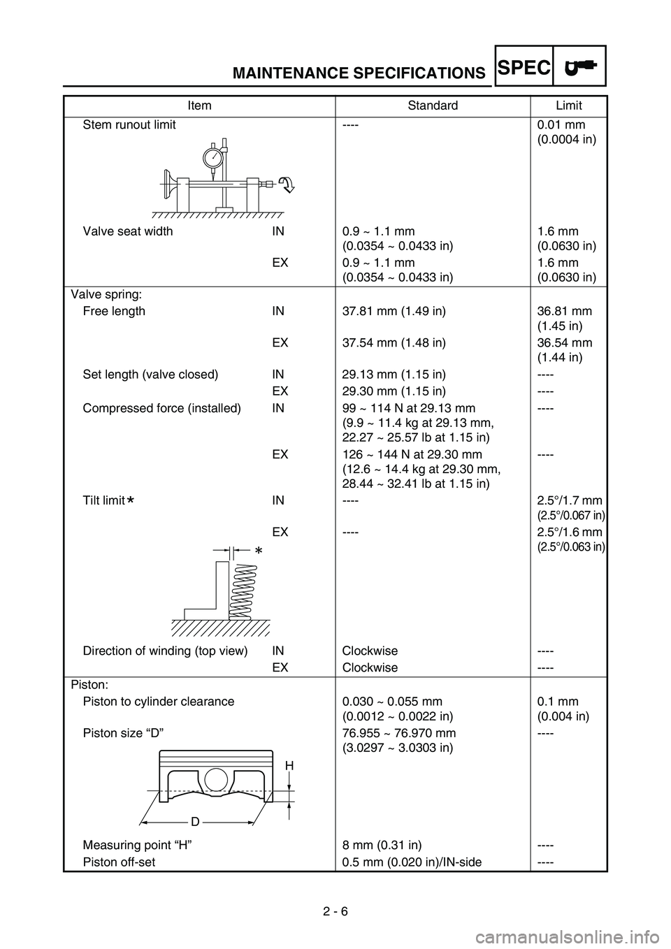
Stem runout limit ---- 0.01 mm
(0.0004 in)
Valve seat width IN 0.9 ~ 1.1 mm
(0.0354 ~ 0.0433 in)1.6 mm
(0.0630 in)
EX 0.9 ~ 1.1 mm
(0.0354 ~ 0.0433 in)1.6 mm
(0.0630 in)
Valve spring:
Free length IN 37.81 mm (1.49 in) 36.81 mm
(1.45 in)
EX 37.54 mm (1.48 in) 36.54 mm
(1.44 in)
Set length (valve closed) IN 29.13 mm (1.15 in) ----
EX 29.30 mm (1.15 in) ----
Compressed force (installed) IN 99 ~ 114 N at 29.13 mm
(9.9 ~ 11.4 kg at 29.13 mm,
22.27 ~ 25.57 lb at 1.15 in)----
EX 126 ~ 144 N at 29.30 mm
(12.6 ~ 14.4 kg at 29.30 mm,
28.44 ~ 32.41 lb at 1.15 in)----
Tilt limit IN ---- 2.5°/1.7 mm
(2.5°/0.067 in)
EX ---- 2.5°/1.6 mm
(2.5°/0.063 in)
Direction of winding (top view) IN Clockwise ----
EX Clockwise ----
Piston:
Piston to cylinder clearance 0.030 ~ 0.055 mm
(0.0012 ~ 0.0022 in)0.1 mm
(0.004 in)
Piston size “D”76.955 ~ 76.970 mm
(3.0297 ~ 3.0303 in)----
Measuring point “H”8 mm (0.31 in) ----
Piston off-set 0.5 mm (0.020 in)/IN-side ----Item Standard Limit
*
H
D
Page 101 of 900

MAINTENANCE SPECIFICATIONS
2 - 8
SPEC
Clutch:
Friction plate thickness 2.9 ~ 3.1 mm (0.114 ~ 0.122 in) 2.7 mm
(0.106 in)
Quantity 9 ----
Clutch plate thickness 1.1 ~ 1.3 mm (0.043 ~ 0.051 in) ----
Quantity 8 ----
Warp limit ---- 0.1 mm
(0.004 in)
Clutch spring free length 37.0 mm (1.46 in) 36.0 mm
(1.42 in)
Quantity 5 ----
Clutch housing thrust clearance 0.10 ~ 0.35 mm
(0.0039 ~ 0.0138 in)----
Clutch housing radial clearance 0.010 ~ 0.044 mm
(0.0004 ~ 0.0017 in)----
Clutch release method Inner push, cam push ----
Shifter:
Shifter type Cam drum and guide bar ----
Guide bar bending limit ---- 0.05 mm
(0.002 in)
Kickstarter:
Type Kick and ratchet type ----
Carburetor:
Type/manufacturer FCR-MX37/KEIHIN
I. D. mark 5UMB B0
Main jet (M.J) #168
Main air jet (M.A.J) #115
Jet needle (J.N) NGSU
Cutaway (C.A) 1.5
Pilot jet (P.J) #42
Pilot air jet (P.A.J) #70
Pilot outlet (P.O)ø0.9
Bypass (B.P)ø1.0
Valve seat size (V.S)ø3.8
Starter jet (G.S) #68
Leak jet (Acc.P) #70
Float height (F.H) 8 mm (0.31 in)
Engine idle speed 1,750 ~ 1,950 r/min
Intake vacuum 31.3 ~ 36.7 kPa
(235 ~ 275 mmHg,
9.25 ~ 10.83 inHg)
Hot starter lever free play 3 ~ 6 mm
(0.12 ~ 0.24 in) Item Standard Limit
Page 105 of 900
MAINTENANCE SPECIFICATIONS
2 - 12
SPEC
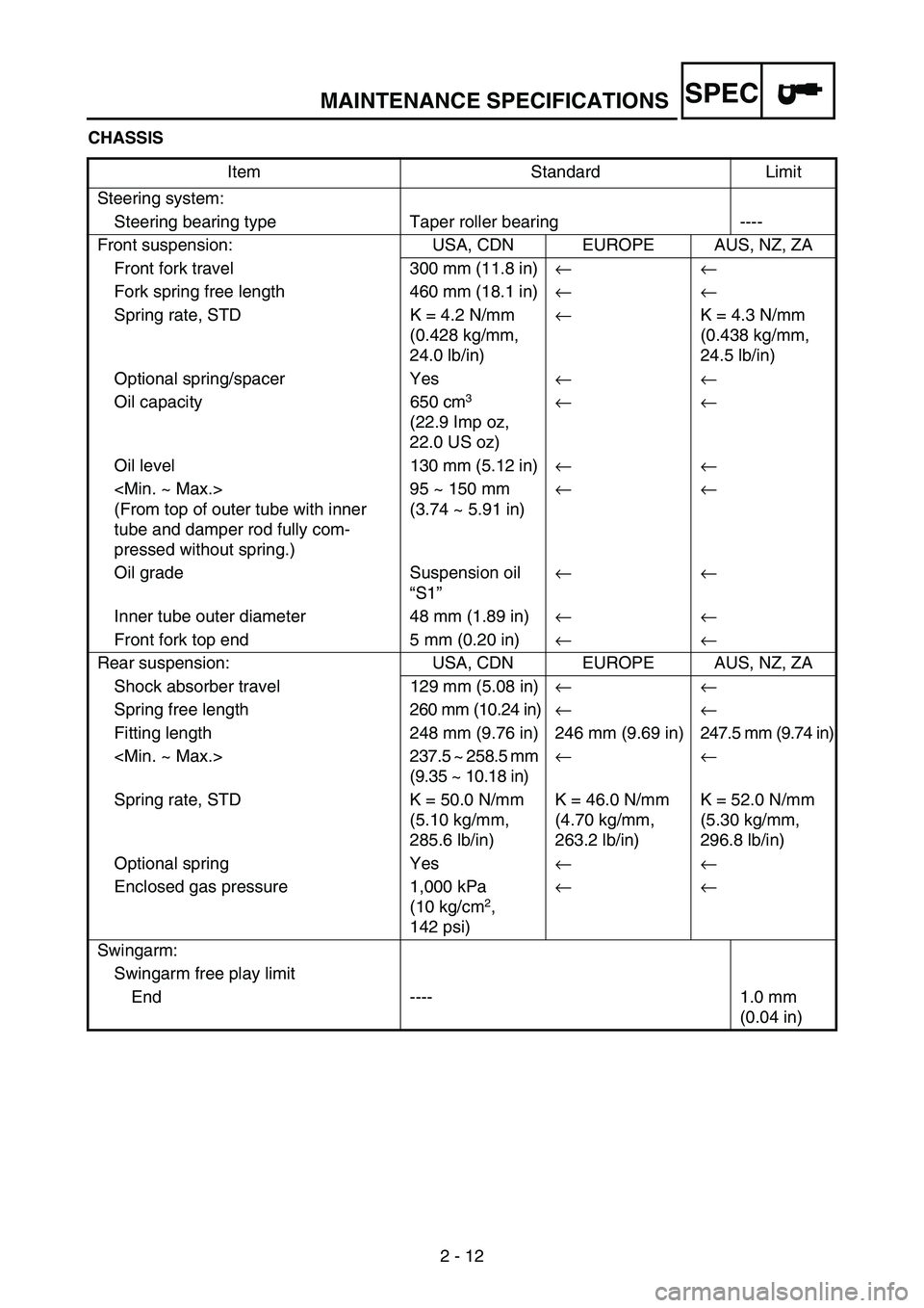
CHASSIS
Item Standard Limit
Steering system:
Steering bearing type Taper roller bearing ----
Front suspension: USA, CDN EUROPE AUS, NZ, ZA
Front fork travel 300 mm (11.8 in)←←
Fork spring free length 460 mm (18.1 in)←←
Spring rate, STD K = 4.2 N/mm
(0.428 kg/mm,
24.0 lb/in)←K = 4.3 N/mm
(0.438 kg/mm,
24.5 lb/in)
Optional spring/spacer Yes←←
Oil capacity 650 cm
3
(22.9 Imp oz,
22.0 US oz) ←←
Oil level 130 mm (5.12 in)←←
(From top of outer tube with inner
tube and damper rod fully com-
pressed without spring.)95 ~ 150 mm
(3.74 ~ 5.91 in)←←
Oil grade Suspension oil
“S1”←←
Inner tube outer diameter 48 mm (1.89 in)←←
Front fork top end 5 mm (0.20 in)←←
Rear suspension: USA, CDN EUROPE AUS, NZ, ZA
Shock absorber travel 129 mm (5.08 in)← ←
Spring free length260 mm (10.24 in)← ←
Fitting length 248 mm (9.76 in) 246 mm (9.69 in) 247.5 mm (9.74 in)
(9.35 ~ 10.18 in)← ←
Spring rate, STD K = 50.0 N/mm
(5.10 kg/mm,
285.6 lb/in)K = 46.0 N/mm
(4.70 kg/mm,
263.2 lb/in)K = 52.0 N/mm
(5.30 kg/mm,
296.8 lb/in)
Optional spring Yes← ←
Enclosed gas pressure 1,000 kPa
(10 kg/cm
2,
142 psi)← ←
Swingarm:
Swingarm free play limit
End ---- 1.0 mm
(0.04 in)
Page 106 of 900
MAINTENANCE SPECIFICATIONS
2 - 13
SPEC
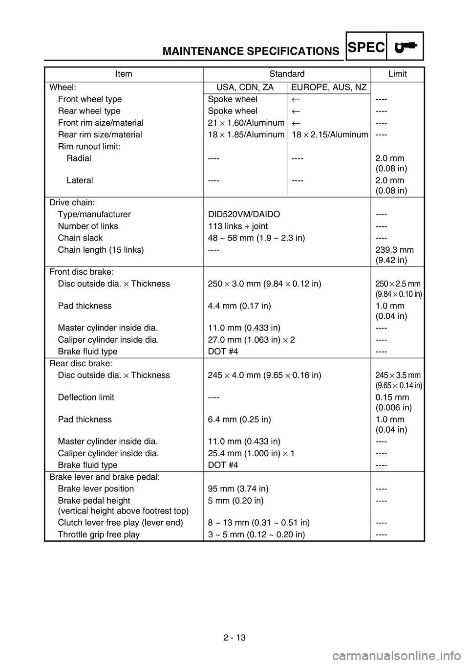
Wheel: USA, CDN, ZA EUROPE, AUS, NZ
Front wheel type Spoke wheel← ----
Rear wheel type Spoke wheel← ----
Front rim size/material 21 × 1.60/Aluminum← ----
Rear rim size/material 18 × 1.85/Aluminum 18 × 2.15/Aluminum ----
Rim runout limit:
Radial ---- ---- 2.0 mm
(0.08 in)
Lateral ---- ---- 2.0 mm
(0.08 in)
Drive chain:
Type/manufacturer DID520VM/DAIDO ----
Number of links 113 links + joint ----
Chain slack 48 ~ 58 mm (1.9 ~ 2.3 in) ----
Chain length (15 links) ---- 239.3 mm
(9.42 in)
Front disc brake:
Disc outside dia. × Thickness 250 × 3.0 mm (9.84 × 0.12 in)
250 × 2.5 mm
(9.84 × 0.10 in)
Pad thickness 4.4 mm (0.17 in) 1.0 mm
(0.04 in)
Master cylinder inside dia. 11.0 mm (0.433 in) ----
Caliper cylinder inside dia. 27.0 mm (1.063 in) × 2 ----
Brake fluid type DOT #4 ----
Rear disc brake:
Disc outside dia. × Thickness 245 × 4.0 mm (9.65 × 0.16 in)
245 × 3.5 mm
(9.65 × 0.14 in)
Deflection limit ---- 0.15 mm
(0.006 in)
Pad thickness 6.4 mm (0.25 in) 1.0 mm
(0.04 in)
Master cylinder inside dia. 11.0 mm (0.433 in) ----
Caliper cylinder inside dia. 25.4 mm (1.000 in) × 1 ----
Brake fluid type DOT #4 ----
Brake lever and brake pedal:
Brake lever position 95 mm (3.74 in) ----
Brake pedal height
(vertical height above footrest top)5 mm (0.20 in) ----
Clutch lever free play (lever end) 8 ~ 13 mm (0.31 ~ 0.51 in) ----
Throttle grip free play 3 ~ 5 mm (0.12 ~ 0.20 in) ----Item Standard Limit
Page 110 of 900
MAINTENANCE SPECIFICATIONS
2 - 17
SPEC
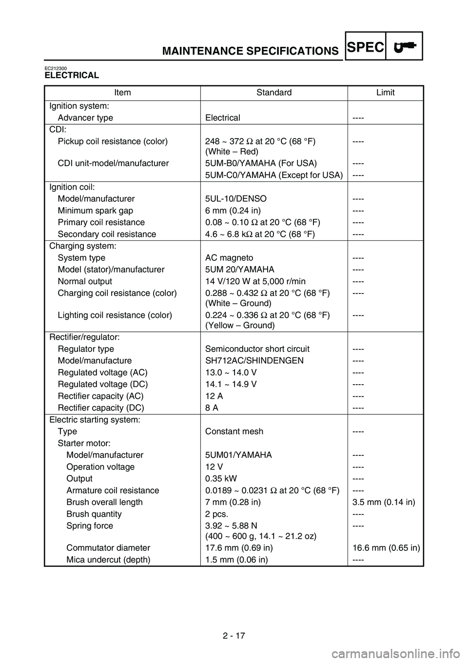
EC212300
ELECTRICAL
Item Standard Limit
Ignition system:
Advancer type Electrical ----
CDI:
Pickup coil resistance (color) 248 ~ 372 Ω at 20°C (68 °F)
(White – Red)----
CDI unit-model/manufacturer 5UM-B0/YAMAHA (For USA) ----
5UM-C0/YAMAHA (Except for USA) ----
Ignition coil:
Model/manufacturer 5UL-10/DENSO ----
Minimum spark gap 6 mm (0.24 in) ----
Primary coil resistance 0.08 ~ 0.10 Ω at 20 °C (68 °F) ----
Secondary coil resistance 4.6 ~ 6.8 kΩ at 20 °C (68 °F) ----
Charging system:
System type AC magneto ----
Model (stator)/manufacturer 5UM 20/YAMAHA ----
Normal output 14 V/120 W at 5,000 r/min ----
Charging coil resistance (color) 0.288 ~ 0.432 Ω at 20 °C (68 °F)
(White – Ground)----
Lighting coil resistance (color) 0.224 ~ 0.336 Ω at 20 °C (68 °F)
(Yellow – Ground)----
Rectifier/regulator:
Regulator type Semiconductor short circuit ----
Model/manufacture SH712AC/SHINDENGEN ----
Regulated voltage (AC) 13.0 ~ 14.0 V ----
Regulated voltage (DC) 14.1 ~ 14.9 V ----
Rectifier capacity (AC) 12 A ----
Rectifier capacity (DC) 8 A ----
Electric starting system:
Type Constant mesh ----
Starter motor:
Model/manufacturer 5UM01/YAMAHA ----
Operation voltage 12 V ----
Output 0.35 kW ----
Armature coil resistance 0.0189 ~ 0.0231 Ω at 20 °C (68 °F) ----
Brush overall length 7 mm (0.28 in) 3.5 mm (0.14 in)
Brush quantity 2 pcs. ----
Spring force 3.92 ~ 5.88 N
(400 ~ 600 g, 14.1 ~ 21.2 oz)----
Commutator diameter 17.6 mm (0.69 in) 16.6 mm (0.65 in)
Mica undercut (depth) 1.5 mm (0.06 in) ----
Page 112 of 900

2 - 19
GENERAL TORQUE SPECIFICATIONS/
DEFINITION OF UNITS
SPEC
EC220001
GENERAL TORQUE SPECIFICATIONS
This chart specifies torque for standard fasten-
ers with standard I.S.O. pitch threads. Torque
specifications for special components or
assemblies are included in the applicable sec-
tions of this book. To avoid warpage, tighten
multi-fastener assemblies in a crisscross fash-
ion, in progressive stages, until full torque is
reached. Unless otherwise specified, torque
specifications call for clean, dry threads. Com-
ponents should be at room temperature.
A: Distance between flats
B: Outside thread diameter
EC230000
DEFINITION OF UNITS
A
(Nut)B
(Bolt)TORQUE
SPECIFICATION
Nm mkg ftlb
10 mm
12 mm
14 mm
17 mm
19 mm
22 mm6 mm
8 mm
10 mm
12 mm
14 mm
16 mm6
15
30
55
85
1300.6
1.5
3.0
5.5
8.5
134.3
11
22
40
61
94
Unit Read Definition Measure
mm
cmmillimeter
centimeter10
-3 meter
10-2 meterLength
Length
kg kilogram 10
3 gram Weight
N Newton 1 kg
× m/sec
2 Force
Nm
m kgNewton meter
Meter kilogramN
× m
m
× kgTorque
Torque
Pa Pascal N/m
2Pressure
N/mm Newton per millimeter N/mm Spring rate
L
cm
3 Liter
Cubic centimeter—
—Volume or capacity
Volume or capacity
r/min Revolution per minute—Engine speed
Page 208 of 900

3 - 1
INSP
ADJ
MAINTENANCE INTERVALS
EC300000
REGULAR INSPECTION AND ADJUSTMENTS
MAINTENANCE INTERVALS
The following schedule is intended as a general guide to maintenance and lubrication. Bear in mind that such factors as
weather, terrain, geographical location, and individual usage will alter the required maintenance and lubrication intervals. If
you are a doubt as to what intervals to follow in maintaining and lubricating your machine, consult your Yamaha dealer.
ItemAfter
break-inEvery
race
Every third
(or
500 km)Every fifth
(or
1,000 km)As
requiredRemarks
ENGINE OIL
Replace
Inspect
VALVES
Check the valve clearances The engine must be cold.
Check the valve seats and
valve stems for wear. Inspect
Replace
VALVE SPRINGS
InspectCheck the free length and
the tilt.
Replace
VALVE LIFTERS
InspectCheck for scratches and
wear.
Replace
CAMSHAFTSInspect the camshaft
surface.
Inspect the decompression
system. Inspect
Replace
TIMING CHAIN SPROCKETS, TIMING
CHAIN
InspectCheck for wear on the teeth
and for damage.
Replace
PISTON
InspectInspect crack
Inspect carbon deposits and
eliminate them. Clean
Replace
PISTON RING
InspectCheck ring end gap
Replace
PISTON PIN
Inspect
Replace
CYLINDER HEADInspect carbon deposits and
eliminate them.
Change gasket Inspect and clean
CYLINDER
Inspect and clean Inspect score marks
Inspect wear
Replace
CLUTCH
Inspect and adjust Inspect housing, friction
plate, clutch plate and spring
Replace
TRANSMISSION
Inspect
Replace bearing
SHIFT FORK, SHIFT CAM, GUIDE BAR
InspectInspect wear
Page 286 of 900
3 - 79
INSP
ADJ
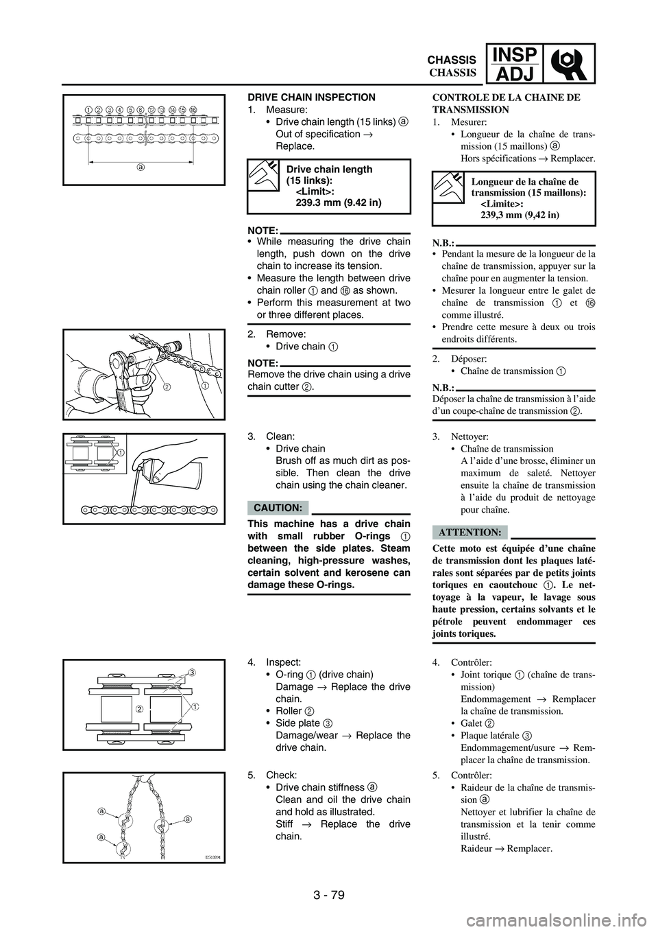
DRIVE CHAIN INSPECTION
1. Measure:
Drive chain length (15 links)
a
Out of specification
→
Replace.
NOTE:While measuring the drive chain
length, push down on the drive
chain to increase its tension.
Measure the length between drive
chain roller
1 and
F as shown.
Perform this measurement at two
or three different places.
2. Remove:
Drive chain
1
NOTE:Remove the drive chain using a drive
chain cutter
2.
Drive chain length
(15 links):
239.3 mm (9.42 in)
3. Clean:
Drive chain
Brush off as much dirt as pos-
sible. Then clean the drive
chain using the chain cleaner.
CAUTION:
This machine has a drive chain
with small rubber O-rings 1
between the side plates. Steam
cleaning, high-pressure washes,
certain solvent and kerosene can
damage these O-rings.
1
4. Inspect:
O-ring
1 (drive chain)
Damage
→ Replace the drive
chain.
Roller
2
Side plate
3
Damage/wear → Replace the
drive chain.
5. Check:
Drive chain stiffness a
Clean and oil the drive chain
and hold as illustrated.
Stiff → Replace the drive
chain.
CONTROLE DE LA CHAINE DE
TRANSMISSION
1. Mesurer:
Longueur de la chaîne de trans-
mission (15 maillons) a
Hors spécifications → Remplacer.
N.B.:
Pendant la mesure de la longueur de la
chaîne de transmission, appuyer sur la
chaîne pour en augmenter la tension.
Mesurer la longueur entre le galet de
chaîne de transmission 1 et F
comme illustré.
Prendre cette mesure à deux ou trois
endroits différents.
2. Déposer:
Chaîne de transmission 1
N.B.:
Déposer la chaîne de transmission à l’aide
d’un coupe-chaîne de transmission 2.
Longueur de la chaîne de
transmission (15 maillons):
239,3 mm (9,42 in)
3. Nettoyer:
Chaîne de transmission
A l’aide d’une brosse, éliminer un
maximum de saleté. Nettoyer
ensuite la chaîne de transmission
à l’aide du produit de nettoyage
pour chaîne.
ATTENTION:
Cette moto est équipée d’une chaîne
de transmission dont les plaques laté-
rales sont séparées par de petits joints
toriques en caoutchouc 1. Le net-
toyage à la vapeur, le lavage sous
haute pression, certains solvants et le
pétrole peuvent endommager ces
joints toriques.
4. Contrôler:
Joint torique 1 (chaîne de trans-
mission)
Endommagement → Remplacer
la chaîne de transmission.
Galet 2
Plaque latérale 3
Endommagement/usure → Rem-
placer la chaîne de transmission.
5. Contrôler:
Raideur de la chaîne de transmis-
sion a
Nettoyer et lubrifier la chaîne de
transmission et la tenir comme
illustré.
Raideur → Remplacer.
CHASSIS
CHASSIS