seats YAMAHA WR 250F 2007 Manuale de Empleo (in Spanish)
[x] Cancel search | Manufacturer: YAMAHA, Model Year: 2007, Model line: WR 250F, Model: YAMAHA WR 250F 2007Pages: 912, tamaño PDF: 23.95 MB
Page 212 of 912

3 - 1
INSP
ADJ
MAINTENANCE INTERVALS
EC300000
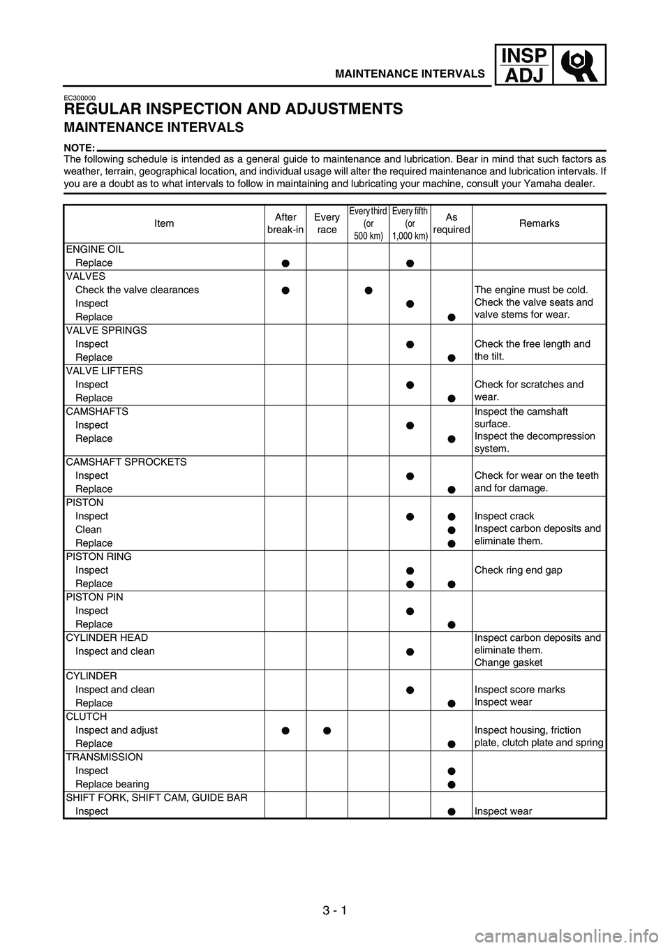
REGULAR INSPECTION AND ADJUSTMENTS
MAINTENANCE INTERVALS
NOTE:The following schedule is intended as a general guide to maintenance and lubrication. Bear in mind that such factors as
weather, terrain, geographical location, and individual usage will alter the required maintenance and lubrication intervals. If
you are a doubt as to what intervals to follow in maintaining and lubricating your machine, consult your Yamaha dealer.
ItemAfter
break-inEvery
race
Every third
(or
500 km)Every fifth
(or
1,000 km)As
requiredRemarks
ENGINE OIL
Replace
VALVES
Check the valve clearances The engine must be cold.
Check the valve seats and
valve stems for wear. Inspect
Replace
VALVE SPRINGS
InspectCheck the free length and
the tilt.
Replace
VALVE LIFTERS
InspectCheck for scratches and
wear.
Replace
CAMSHAFTSInspect the camshaft
surface.
Inspect the decompression
system. Inspect
Replace
CAMSHAFT SPROCKETS
InspectCheck for wear on the teeth
and for damage.
Replace
PISTON
InspectInspect crack
Inspect carbon deposits and
eliminate them. Clean
Replace
PISTON RING
InspectCheck ring end gap
Replace
PISTON PIN
Inspect
Replace
CYLINDER HEADInspect carbon deposits and
eliminate them.
Change gasket Inspect and clean
CYLINDER
Inspect and clean Inspect score marks
Inspect wear
Replace
CLUTCH
Inspect and adjust Inspect housing, friction
plate, clutch plate and spring
Replace
TRANSMISSION
Inspect
Replace bearing
SHIFT FORK, SHIFT CAM, GUIDE BAR
InspectInspect wear
Page 478 of 912

5 - 71
ENGCYLINDER HEAD
INSPECTION
Cylinder head
1. Eliminate:
Carbon deposits
(from the combustion cham-
bers)
Use a rounded scraper.
NOTE:Do not use a sharp instrument to
avoid damaging or scratching:
Spark plug threads
Valve seats
2. Inspect:
Cylinder head
Scratches/damage
→
Replace.
3. Measure:
Cylinder head warpage
Out of specification
→ Resur-
face.
Cylinder head warpage:
Less than 0.05 mm
(0.002 in)
Warpage measurement and
resurfacing steps:
Place a straightedge and a
feeler gauge across the cylinder
head.
Use a feeler gauge to measure
the warpage.
If the warpage is out of specifi-
cation, resurface the cylinder
head.
Place a 400 ~ 600 grit wet
sandpaper on the surface plate,
and resurface the head using a
figure-eight sanding pattern.
NOTE:To ensure an even surface rotate
the cylinder head several times.
ASSEMBLY AND INSTALLATION
Cylinder head
1. Install:
Dowel pin
1
Cylinder head gasket
2
Timing chain guide
(exhaust side)
3
Cylinder head
4
NOTE:While pulling up the timing chain,
install the timing chain guide
(exhaust side) and cylinder head.
New
CONTROLE
Culasse
1. Eliminer:
Dépôts de calamine
(des chambres de combustion)
Utiliser un grattoir arrondi.
N.B.:
Ne pas utiliser d’instrument pointu pour
éviter d’endommager ou de griffer:
Filets de bougie
Sièges de soupapes
2. Contrôler:
Culasse
Rayures/endommagement →
Remplacer.
3. Mesurer:
Déformation de la culasse
Hors spécifications → Rectifier.
Déformation de la culasse:
Inférieure à 0,05 mm
(0,002 in)
Etapes de la mesure de la limite de
déformation et de la rectification:
Placer un réglet et une jauge
d’épaisseur à lames sur la culasse.
Utiliser une jauge d’épaisseur à
lames pour mesurer la déforma-
tion.
Si la déformation est hors spécifi-
cations, rectifier la culasse.
Placer un morceau de papier émeri
humide 400 à 600 sur le marbre et
rectifier la culasse en décrivant des
“huit”.
N.B.:
Pour obtenir une surface régulière,
tourner la culasse à plusieurs reprises.
ASSEMBLAGE ET MONTAGE
Culasse
1. Monter:
Goujon 1
Joint de culasse 2
Patin de chaîne de distribution
(côté échappement) 3
Culasse 4
N.B.:
Tout en soulevant la chaîne de distribu-
tion, monter le patin de chaîne de distri-
bution (côté échappement) et la culasse.
New
CULASSE