torque YAMAHA WR 250F 2007 Notices Demploi (in French)
[x] Cancel search | Manufacturer: YAMAHA, Model Year: 2007, Model line: WR 250F, Model: YAMAHA WR 250F 2007Pages: 912, PDF Size: 23.95 MB
Page 324 of 912
3 - 113
INSP
ADJ
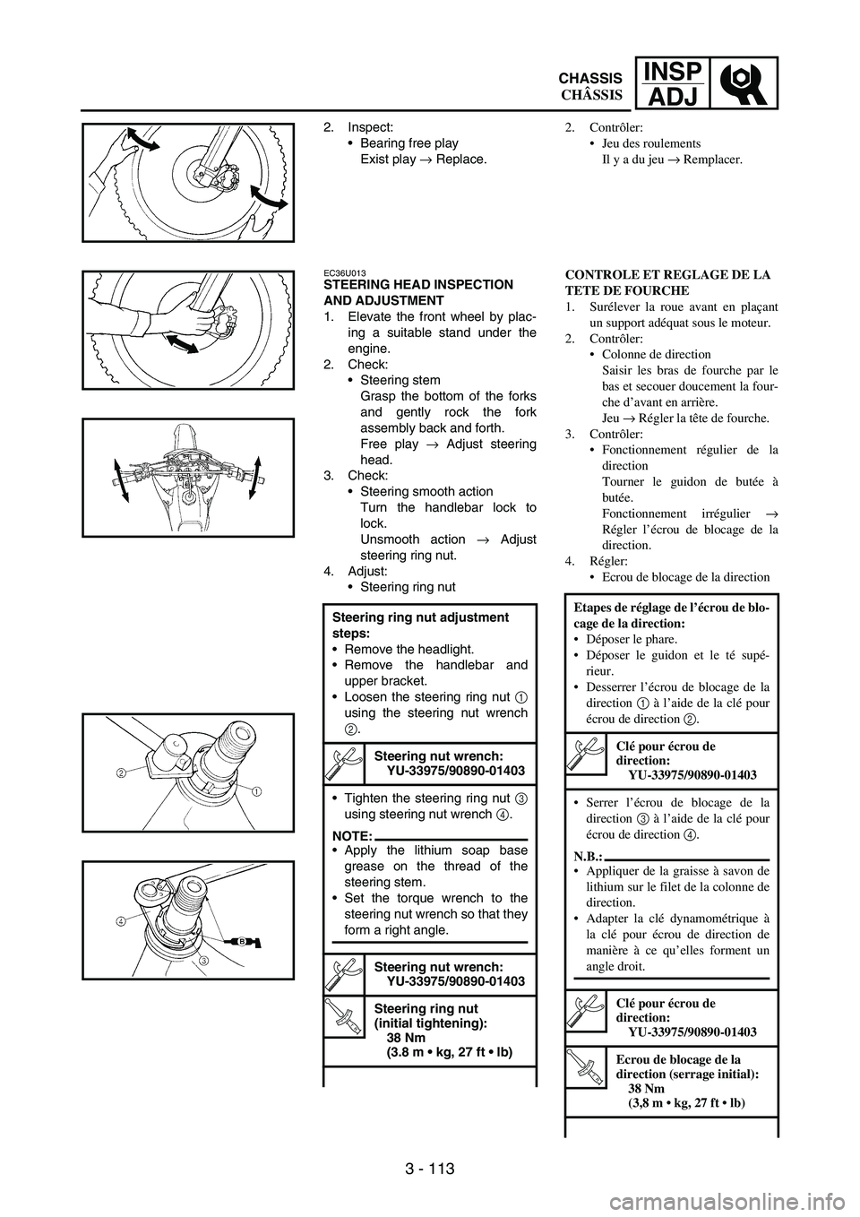
2. Inspect:
Bearing free play
Exist play
→ Replace.
EC36U013STEERING HEAD INSPECTION
AND ADJUSTMENT
1. Elevate the front wheel by plac-
ing a suitable stand under the
engine.
2. Check:
Steering stem
Grasp the bottom of the forks
and gently rock the fork
assembly back and forth.
Free play
→ Adjust steering
head.
3. Check:
Steering smooth action
Turn the handlebar lock to
lock.
Unsmooth action
→ Adjust
steering ring nut.
4. Adjust:
Steering ring nut
Steering ring nut adjustment
steps:
Remove the headlight.
Remove the handlebar and
upper bracket.
Loosen the steering ring nut
1
using the steering nut wrench
2.
Steering nut wrench:
YU-33975/90890-01403
Tighten the steering ring nut
3
using steering nut wrench
4.
NOTE:Apply the lithium soap base
grease on the thread of the
steering stem.
Set the torque wrench to the
steering nut wrench so that they
form a right angle.
Steering nut wrench:
YU-33975/90890-01403
T R..
Steering ring nut
(initial tightening):
38 Nm
(3.8 m kg, 27 ft lb)
2. Contrôler:
Jeu des roulements
Il y a du jeu → Remplacer.
CONTROLE ET REGLAGE DE LA
TETE DE FOURCHE
1. Surélever la roue avant en plaçant
un support adéquat sous le moteur.
2. Contrôler:
Colonne de direction
Saisir les bras de fourche par le
bas et secouer doucement la four-
che d’avant en arrière.
Jeu → Régler la tête de fourche.
3. Contrôler:
Fonctionnement régulier de la
direction
Tourner le guidon de butée à
butée.
Fonctionnement irrégulier →
Régler l’écrou de blocage de la
direction.
4. Régler:
Ecrou de blocage de la direction
Etapes de réglage de l’écrou de blo-
cage de la direction:
Déposer le phare.
Déposer le guidon et le té supé-
rieur.
Desserrer l’écrou de blocage de la
direction 1 à l’aide de la clé pour
écrou de direction 2.
Clé pour écrou de
direction:
YU-33975/90890-01403
Serrer l’écrou de blocage de la
direction 3 à l’aide de la clé pour
écrou de direction 4.
N.B.:
Appliquer de la graisse à savon de
lithium sur le filet de la colonne de
direction.
Adapter la clé dynamométrique à
la clé pour écrou de direction de
manière à ce qu’elles forment un
angle droit.
Clé pour écrou de
direction:
YU-33975/90890-01403
T R..
Ecrou de blocage de la
direction (serrage initial):
38 Nm
(3,8 m kg, 27 ft lb)
CHASSIS
CHÂSSIS
Page 398 of 912
4 - 39
TUNSETTING
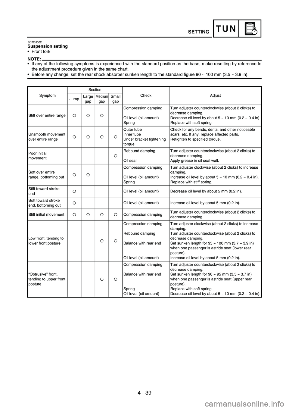
EC72H002Suspension setting
Front fork
NOTE:If any of the following symptoms is experienced with the standard position as the base, make resetting by reference to
the adjustment procedure given in the same chart.
Before any change, set the rear shock absorber sunken length to the standard figure 90 ~ 100 mm (3.5 ~ 3.9 in).
SymptomSection
Check Adjust
JumpLarge
gapMedium
gapSmall
gap
Stiff over entire rangeCompression damping
Oil level (oil amount)
SpringTurn adjuster counterclockwise (about 2 clicks) to
decrease damping.
Decrease oil level by about 5 ~ 10 mm (0.2 ~ 0.4 in).
Replace with soft spring.
Unsmooth movement
over entire rangeOuter tube
Inner tube
Under bracket tightening
torqueCheck for any bends, dents, and other noticeable
scars, etc. If any, replace affected parts.
Retighten to specified torque.
Poor initial
movementRebound damping
Oil sealTurn adjuster counterclockwise (about 2 clicks) to
decrease damping.
Apply grease in oil seal wall.
Soft over entire
range, bottoming outCompression damping
Oil level (oil amount)
SpringTurn adjuster clockwise (about 2 clicks) to increase
damping.
Increase oil level by about 5 ~ 10 mm (0.2 ~ 0.4 in).
Replace with stiff spring.
Stiff toward stroke
endOil level (oil amount) Decrease oil level by about 5 mm (0.2 in).
Soft toward stroke
end, bottoming outOil level (oil amount) Increase oil level by about 5 mm (0.2 in).
Stiff initial movement Compression dampingTurn adjuster counterclockwise (about 2 clicks) to
decrease damping.
Low front, tending to
lower front postureCompression damping
Rebound damping
Balance with rear end
Oil level (oil amount)Turn adjuster clockwise (about 2 clicks) to increase
damping.
Turn adjuster counterclockwise (about 2 clicks) to
decrease damping.
Set sunken length for 95 ~ 100 mm (3.7 ~ 3.9 in)
when one passenger is astride seat (lower rear
posture).
Increase oil level by about 5 mm (0.2 in).
“Obtrusive” front,
tending to upper front
postureCompression damping
Balance with rear end
Spring
Oil lever (oil amount)Turn adjuster counterclockwise (about 2 clicks) to
decrease damping.
Set sunken length for 90 ~ 95 mm (3.5 ~ 3.7 in)
when one passenger is astride seat (upper rear
posture).
Replace with soft spring.
Decrease oil level by about 5 ~ 10 mm (0.2 ~ 0.4 in).
Page 468 of 912
5 - 61
ENGCAMSHAFTS
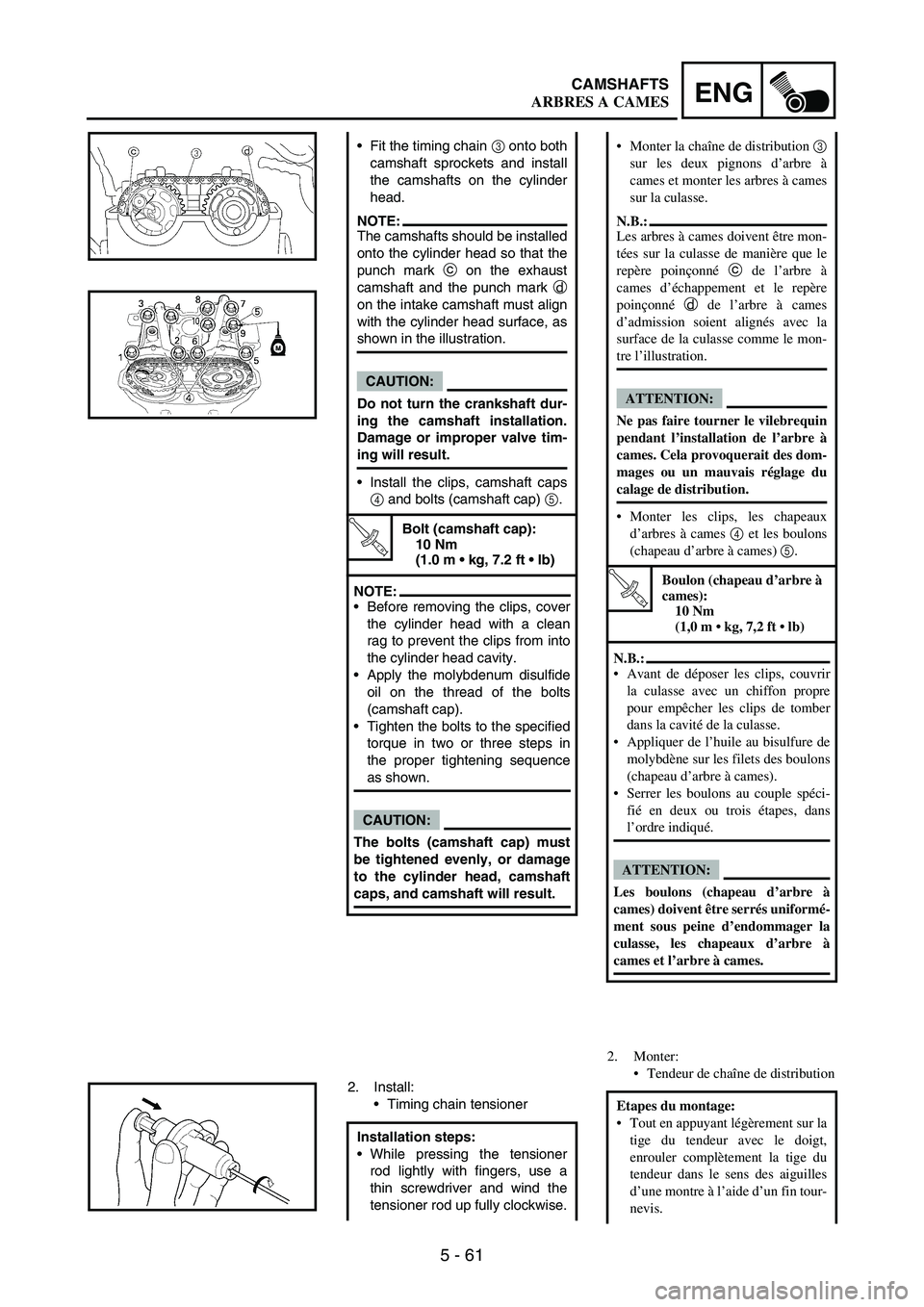
Fit the timing chain
3 onto both
camshaft sprockets and install
the camshafts on the cylinder
head.
NOTE:The camshafts should be installed
onto the cylinder head so that the
punch mark
c on the exhaust
camshaft and the punch mark
d
on the intake camshaft must align
with the cylinder head surface, as
shown in the illustration.
CAUTION:
Do not turn the crankshaft dur-
ing the camshaft installation.
Damage or improper valve tim-
ing will result.
Install the clips, camshaft caps
4 and bolts (camshaft cap)
5.
T R..
Bolt (camshaft cap):
10 Nm
(1.0 m kg, 7.2 ft lb)
NOTE:Before removing the clips, cover
the cylinder head with a clean
rag to prevent the clips from into
the cylinder head cavity.
Apply the molybdenum disulfide
oil on the thread of the bolts
(camshaft cap).
Tighten the bolts to the specified
torque in two or three steps in
the proper tightening sequence
as shown.
CAUTION:
The bolts (camshaft cap) must
be tightened evenly, or damage
to the cylinder head, camshaft
caps, and camshaft will result.
2. Install:
Timing chain tensioner
Installation steps:
While pressing the tensioner
rod lightly with fingers, use a
thin screwdriver and wind the
tensioner rod up fully clockwise.
2. Monter:
Tendeur de chaîne de distribution Monter la chaîne de distribution 3
sur les deux pignons d’arbre à
cames et monter les arbres à cames
sur la culasse.
N.B.:
Les arbres à cames doivent être mon-
tées sur la culasse de manière que le
repère poinçonné c de l’arbre à
cames d’échappement et le repère
poinçonné d de l’arbre à cames
d’admission soient alignés avec la
surface de la culasse comme le mon-
tre l’illustration.
ATTENTION:
Ne pas faire tourner le vilebrequin
pendant l’installation de l’arbre à
cames. Cela provoquerait des dom-
mages ou un mauvais réglage du
calage de distribution.
Monter les clips, les chapeaux
d’arbres à cames 4 et les boulons
(chapeau d’arbre à cames) 5.
T R..
Boulon (chapeau d’arbre à
cames):
10 Nm
(1,0 m kg, 7,2 ft lb)
N.B.:
Avant de déposer les clips, couvrir
la culasse avec un chiffon propre
pour empêcher les clips de tomber
dans la cavité de la culasse.
Appliquer de l’huile au bisulfure de
molybdène sur les filets des boulons
(chapeau d’arbre à cames).
Serrer les boulons au couple spéci-
fié en deux ou trois étapes, dans
l’ordre indiqué.
ATTENTION:
Les boulons (chapeau d’arbre à
cames) doivent être serrés uniformé-
ment sous peine d’endommager la
culasse, les chapeaux d’arbre à
cames et l’arbre à cames.
Etapes du montage:
Tout en appuyant légèrement sur la
tige du tendeur avec le doigt,
enrouler complètement la tige du
tendeur dans le sens des aiguilles
d’une montre à l’aide d’un fin tour-
nevis.
ARBRES A CAMES
Page 470 of 912
5 - 63
ENGCAMSHAFTS
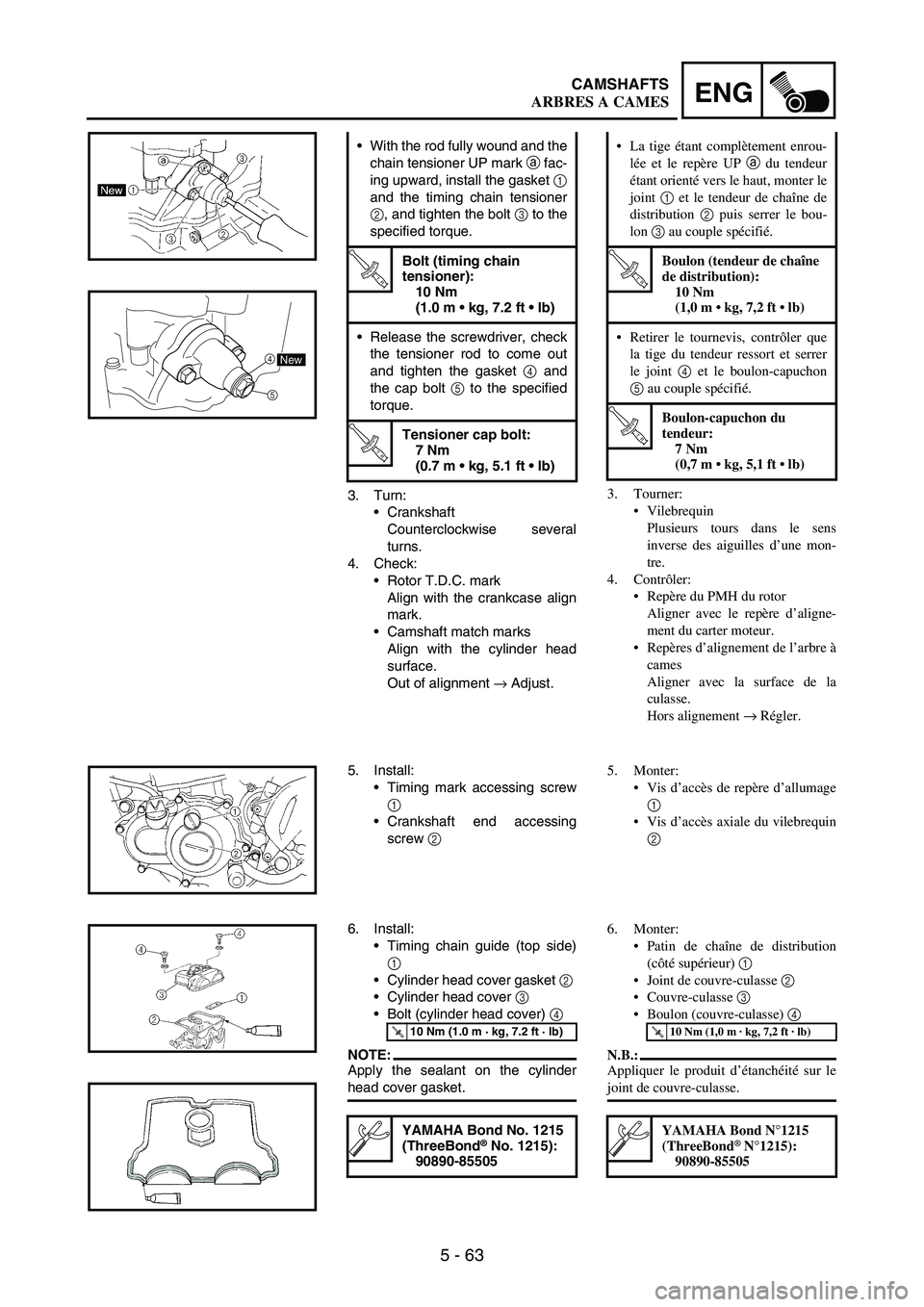
3. Turn:
Crankshaft
Counterclockwise several
turns.
4. Check:
Rotor T.D.C. mark
Align with the crankcase align
mark.
Camshaft match marks
Align with the cylinder head
surface.
Out of alignment
→ Adjust. With the rod fully wound and the
chain tensioner UP mark
a fac-
ing upward, install the gasket
1
and the timing chain tensioner
2, and tighten the bolt
3 to the
specified torque.
T R..
Bolt (timing chain
tensioner):
10 Nm
(1.0 m kg, 7.2 ft lb)
Release the screwdriver, check
the tensioner rod to come out
and tighten the gasket
4 and
the cap bolt
5 to the specified
torque.
T R..
Tensioner cap bolt:
7 Nm
(0.7 m kg, 5.1 ft lb)
5
4New
5. Install:
Timing mark accessing screw
1
Crankshaft end accessing
screw
2
6. Install:
Timing chain guide (top side)
1
Cylinder head cover gasket
2
Cylinder head cover
3
Bolt (cylinder head cover)
4
NOTE:Apply the sealant on the cylinder
head cover gasket.
T R..10 Nm (1.0 m · kg, 7.2 ft · lb)
YAMAHA Bond No. 1215
(ThreeBond® No. 1215):
90890-85505
3. Tourner:
Vilebrequin
Plusieurs tours dans le sens
inverse des aiguilles d’une mon-
tre.
4. Contrôler:
Repère du PMH du rotor
Aligner avec le repère d’aligne-
ment du carter moteur.
Repères d’alignement de l’arbre à
cames
Aligner avec la surface de la
culasse.
Hors alignement → Régler. La tige étant complètement enrou-
lée et le repère UP a du tendeur
étant orienté vers le haut, monter le
joint 1 et le tendeur de chaîne de
distribution 2 puis serrer le bou-
lon 3 au couple spécifié.
T R..
Boulon (tendeur de chaîne
de distribution):
10 Nm
(1,0 m kg, 7,2 ft lb)
Retirer le tournevis, contrôler que
la tige du tendeur ressort et serrer
le joint 4 et le boulon-capuchon
5 au couple spécifié.
T R..
Boulon-capuchon du
tendeur:
7 Nm
(0,7 m kg, 5,1 ft lb)
5. Monter:
Vis d’accès de repère d’allumage
1
Vis d’accès axiale du vilebrequin
2
6. Monter:
Patin de chaîne de distribution
(côté supérieur) 1
Joint de couvre-culasse 2
Couvre-culasse 3
Boulon (couvre-culasse) 4
N.B.:
Appliquer le produit d’étanchéité sur le
joint de couvre-culasse.
T R..10 Nm (1,0 m · kg, 7,2 ft · lb)
YAMAHA Bond N°1215
(ThreeBond® N°1215):
90890-85505
ARBRES A CAMES
Page 592 of 912
5 - 185
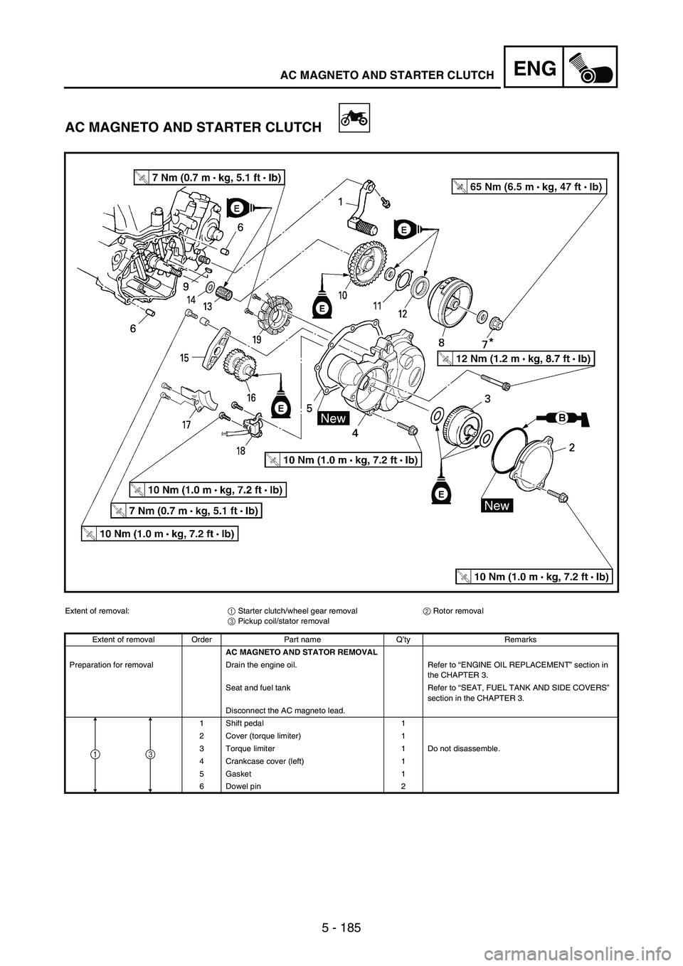
ENGAC MAGNETO AND STARTER CLUTCH
AC MAGNETO AND STARTER CLUTCH
Extent of removal:
1 Starter clutch/wheel gear removal
2 Rotor removal
3 Pickup coil/stator removal
Extent of removal Order Part name Q’ty Remarks
AC MAGNETO AND STATOR REMOVAL
Preparation for removal Drain the engine oil. Refer to “ENGINE OIL REPLACEMENT” section in
the CHAPTER 3.
Seat and fuel tank Refer to “SEAT, FUEL TANK AND SIDE COVERS”
section in the CHAPTER 3.
Disconnect the AC magneto lead.
1 Shift pedal 1
2 Cover (torque limiter) 1
3 Torque limiter 1 Do not disassemble.
4 Crankcase cover (left) 1
5 Gasket 1
6 Dowel pin 2
31
Page 604 of 912
5 - 197
ENGAC MAGNETO AND STARTER CLUTCH
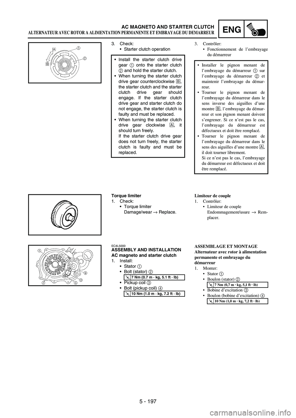
3. Check:
Starter clutch operation
Install the starter clutch drive
gear
1 onto the starter clutch
2 and hold the starter clutch.
When turning the starter clutch
drive gear counterclockwise
É,
the starter clutch and the starter
clutch drive gear should
engage. If the starter clutch
drive gear and starter clutch do
not engage, the starter clutch is
faulty and must be replaced.
When turning the starter clutch
drive gear clockwise
È, it
should turn freely.
If the starter clutch drive gear
does not turn freely, the starter
clutch is faulty and must be
replaced.
Torque limiter
1. Check:
Torque limiter
Damage/wear
→ Replace.
EC4L5000ASSEMBLY AND INSTALLATION
AC magneto and starter clutch
1. Install:
Stator
1
Bolt (stator)
2
Pickup coil
3
Bolt (pickup coil)
4
T R..7 Nm (0.7 m · kg, 5.1 ft · lb)
T R..10 Nm (1.0 m · kg, 7.2 ft · lb)
3. Contrôler:
Fonctionnement de l’embrayage
du démarreur
Installer le pignon menant de
l’embrayage du démarreur 1 sur
l’embrayage du démarreur 2 et
maintenir l’embrayage du démar-
reur.
Tourner le pignon menant de
l’embrayage du démarreur dans le
sens inverse des aiguilles d’une
montre É, l’embrayage du démar-
reur et son pignon menant doivent
s’engrener. Si ce n’est pas le cas,
l’embrayage du démarreur est
défectueux et doit être remplacé.
Tourner le pignon menant de
l’embrayage du démarreur dans le
sens des aiguilles d’une montre È,
il doit tourner librement.
Si ce n’est pas le cas, l’embrayage
du démarreur est défectueux et doit
être remplacé.
Limiteur de couple
1. Contrôler:
Limiteur de couple
Endommagement/usure → Rem-
placer.
ASSEMBLAGE ET MONTAGE
Alternateur avec rotor à alimentation
permanente et embrayage du
démarreur
1. Monter:
Stator 1
Boulon (stator) 2
Bobine d’excitation 3
Boulon (bobine d’excitation) 4
T R..7 Nm (0,7 m · kg, 5,1 ft · lb)
T R..10 Nm (1,0 m · kg, 7,2 ft · lb)
ALTERNATEUR AVEC ROTOR A ALIMENTATION PERMANENTE ET EMBRAYAGE DU DEMARREUR
Page 610 of 912

5 - 203
ENGAC MAGNETO AND STARTER CLUTCH
9. Install:
Washer (rotor)
Nut (rotor)
1
Use the sheave holder
2.
NOTE:Tighten the rotor nut to 65 Nm
(6.5 mkg, 47 ftlb), loosen and
retighten the rotor nut to 65 Nm
(6.5 m kg, 47 ft lb).
T R..65 Nm (6.5 m · kg, 47 ft · lb)
Sheave holder:
YS-1880-A/
90890-01701
2
1
10. Install:
Dowel pin
Gasket [crankcase cover (left)]
Crankcase cover (left)
1
Bolt [crankcase cover (left)]
2
Bolt [crankcase cover (left)]
3
NOTE:Tighten the bolts in stage, using a
crisscross pattern.
T R..10 Nm (1.0 m · kg, 7.2 ft · lb)
T R..12 Nm (1.2 m · kg, 8.7 ft · lb)
32
3
2
1New
11. Install:
Washer 1
Torque limiter 2
Washer 3
NOTE:Apply the engine oil to the shaft and
washers.
E
1
2
3
12. Install:
O-ring
Cover (idle gear 1) 1
Bolt 2
NOTE:Apply the lithium soap base grease
on the O-ring.
Install the cover (idle gear 1) with
its mark a facing upward.
T R..10 Nm (1.0 m · kg, 7.2 ft · lb)
a
2
1
2New
9. Monter:
Rondelle (rotor)
Ecrou (rotor) 1
Utiliser la clé à sangle 2.
N.B.:
Serrer l’écrou du rotor à 65 Nm
(6,5 mkg, 47 ftlb), desserrer puis
resserrer l’écrou du rotor à 65 Nm
(6,5 m kg, 47 ft lb).
T R..65 Nm (6,5 m · kg, 47 ft · lb)
Clé à sangle:
YS-1880-A/90890-01701
10. Monter:
Goujon
Joint [couvercle de carter (gauche)]
Couvercle de carter (gauche) 1
Boulon
[couvercle de carter (gauche)] 2
Boulon
[couvercle de carter (gauche)] 3
N.B.:
Serrer les boulons par étapes et en procé-
dant en croix.
T R..10 Nm (1,0 m · kg, 7,2 ft · lb)
T R..12 Nm (1,2 m · kg, 8,7 ft · lb)
New
11. Monter:
Rondelle 1
Limiteur de couple 2
Rondelle 3
N.B.:
Appliquer de l’huile moteur sur l’arbre
et les rondelles.
12. Monter:
Joint torique
Couvercle (pignon fou 1) 1
Boulon 2
N.B.:
Appliquer de la graisse à savon de
lithium sur le joint torique.
Monter le couvercle (pignon fou 1) en
orientant son repère a vers le haut.
T R..10 Nm (1,0 m · kg, 7,2 ft · lb)
New
ALTERNATEUR AVEC ROTOR A ALIMENTATION PERMANENTE ET EMBRAYAGE DU DEMARREUR
Page 748 of 912
6 - 85
CHASFRONT FORK
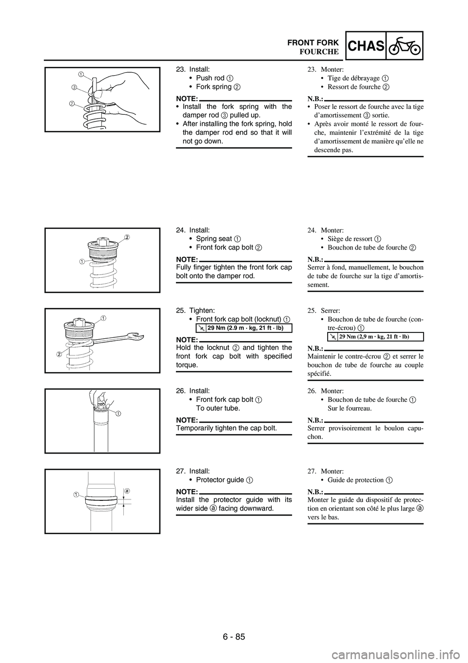
23. Install:
Push rod
1
Fork spring
2
NOTE:Install the fork spring with the
damper rod
3 pulled up.
After installing the fork spring, hold
the damper rod end so that it will
not go down.
24. Install:
Spring seat
1
Front fork cap bolt
2
NOTE:Fully finger tighten the front fork cap
bolt onto the damper rod.
25. Tighten:
Front fork cap bolt (locknut)
1
NOTE:Hold the locknut
2 and tighten the
front fork cap bolt with specified
torque.
T R..29 Nm (2.9 m · kg, 21 ft · lb)
26. Install:
Front fork cap bolt
1
To outer tube.
NOTE:Temporarily tighten the cap bolt.
27. Install:
Protector guide
1
NOTE:Install the protector guide with its
wider side
a facing downward.
23. Monter:
Tige de débrayage 1
Ressort de fourche 2
N.B.:
Poser le ressort de fourche avec la tige
d’amortissement 3 sortie.
Après avoir monté le ressort de four-
che, maintenir l’extrémité de la tige
d’amortissement de manière qu’elle ne
descende pas.
24. Monter:
Siège de ressort 1
Bouchon de tube de fourche 2
N.B.:
Serrer à fond, manuellement, le bouchon
de tube de fourche sur la tige d’amortis-
sement.
25. Serrer:
Bouchon de tube de fourche (con-
tre-écrou) 1
N.B.:
Maintenir le contre-écrou 2 et serrer le
bouchon de tube de fourche au couple
spécifié.
T R..29 Nm (2,9 m · kg, 21 ft · lb)
26. Monter:
Bouchon de tube de fourche 1
Sur le fourreau.
N.B.:
Serrer provisoirement le boulon capu-
chon.
27. Monter:
Guide de protection 1
N.B.:
Monter le guide du dispositif de protec-
tion en orientant son côté le plus large a
vers le bas.
FOURCHE
Page 750 of 912

6 - 87
CHASFRONT FORK
Installation
1. Install:
Front fork
1
NOTE:Temporarily tighten the pinch bolts
(lower bracket).
Do not tighten the pinch bolts
(upper bracket) yet.
2. Tighten:
Front fork cap bolt
1
3. Adjust:
Front fork top end
a
T R..30 Nm (3.0 m · kg, 22 ft · lb)
Front fork top end
(standard) a
:
5 mm (0.20 in)
4. Tighten:
Pinch bolt (upper bracket)
1
Pinch bolt (lower bracket)
2
CAUTION:
Tighten the lower bracket to speci-
fied torque. If torqued too much, it
may cause the front fork to mal-
function.
T R..21 Nm (2.1 m · kg, 15 ft · lb)
T R..21 Nm (2.1 m · kg, 15 ft · lb)
5. Install:
Speed sensor lead
1
Plate 1
2
Bolt (plate 1)
3
To right protector
4.
NOTE:Install the speed sensor lead so that
its paint
a directs as shown and
align the bottom
b of the plate 1 with
the same paint.
T R..4 Nm (0.4 m · kg, 2.9 ft · lb)ab
4 31
2
Montage
1. Monter:
Fourche 1
N.B.:
Serrer provisoirement les boulons de
pincement (té inférieur).
Ne pas encore serrer les boulons de
pincement (té supérieur).
2. Serrer:
Bouchon de tube de fourche 1
3. Régler:
Extrémité supérieure de la four-
che avant a
T R..30 Nm (3,0 m · kg, 22 ft · lb)
Sommet de bras de fourche
(standard) a:
5 mm (0,20 in)
4. Serrer:
Boulon de pincement (té supé-
rieur) 1
Boulon de pincement (té infé-
rieur) 2
ATTENTION:
Serrer le té inférieur au couple spéci-
fié. Un serrage excessif peut compro-
mettre le bon fonctionnement de la
fourche avant.
T R..21 Nm (2,1 m · kg, 15 ft · lb)
T R..21 Nm (2,1 m · kg, 15 ft · lb)
5. Monter:
Fil du capteur de vitesse 1
Plaque 1 2
Boulon (plaque 1) 3
Vers le dispositif de protection
(droite) 4.
N.B.:
Monter le fil du capteur de vitesse de
sorte que le repère a soit orienté comme
illustré et aligner le bas b de la plaque 1
sur cette même marque.
T R..4 Nm (0,4 m · kg, 2,9 ft · lb)
FOURCHE
Page 782 of 912
6 - 119
CHASSTEERING
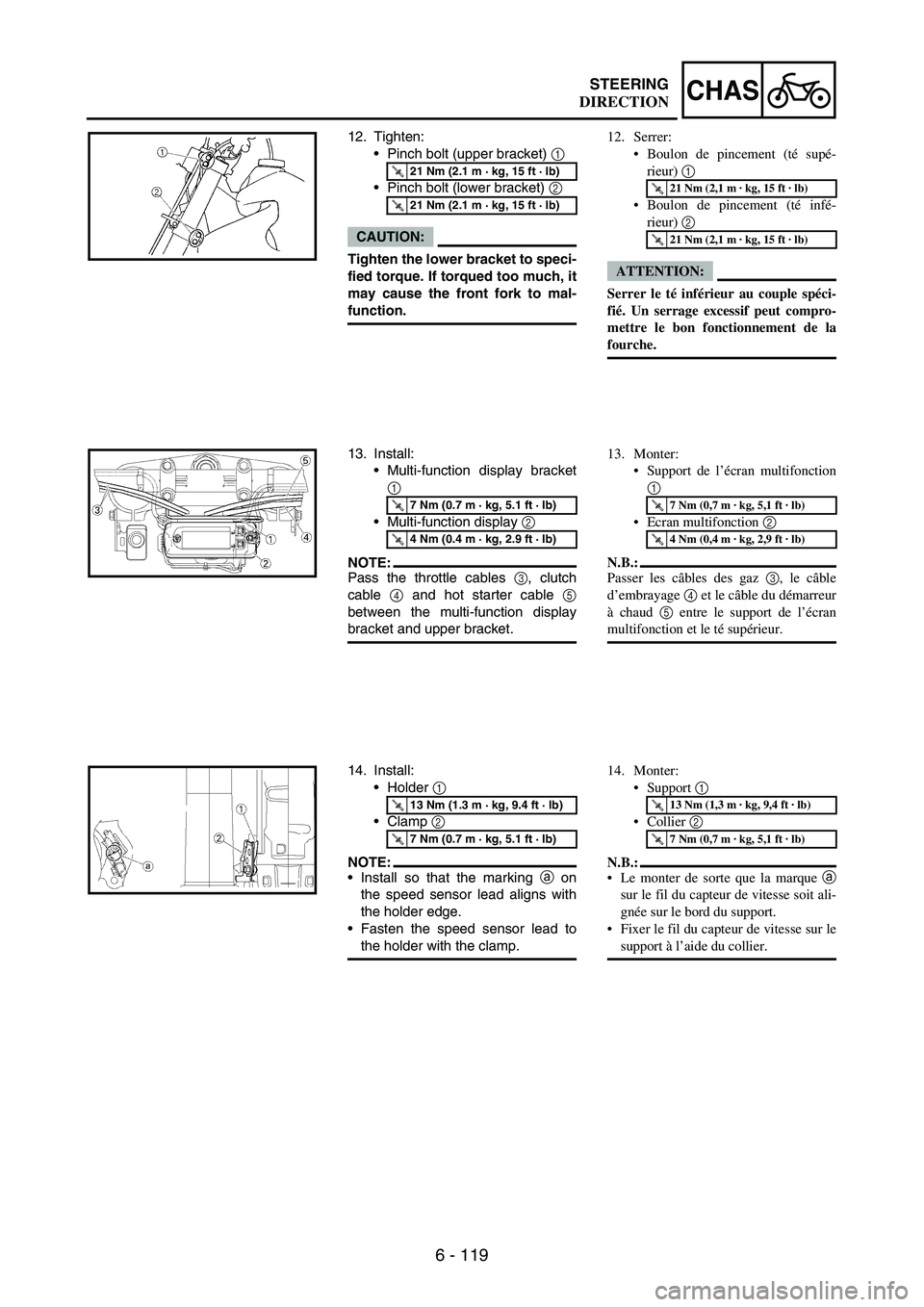
12. Tighten:
•Pinch bolt (upper bracket)
1
•Pinch bolt (lower bracket)
2
CAUTION:
Tighten the lower bracket to speci-
fied torque. If torqued too much, it
may cause the front fork to mal-
function.
T R..21 Nm (2.1 m · kg, 15 ft · lb)
T R..21 Nm (2.1 m · kg, 15 ft · lb)
13. Install:
•Multi-function display bracket
1
•Multi-function display
2
NOTE:Pass the throttle cables
3, clutch
cable
4 and hot starter cable
5
between the multi-function display
bracket and upper bracket.
T R..7 Nm (0.7 m · kg, 5.1 ft · lb)
T R..4 Nm (0.4 m · kg, 2.9 ft · lb)
14. Install:
•Holder
1
•Clamp
2
NOTE:•Install so that the marking
a on
the speed sensor lead aligns with
the holder edge.
•Fasten the speed sensor lead to
the holder with the clamp.
T R..13 Nm (1.3 m · kg, 9.4 ft · lb)
T R..7 Nm (0.7 m · kg, 5.1 ft · lb)
12. Serrer:
Boulon de pincement (té supé-
rieur) 1
Boulon de pincement (té infé-
rieur) 2
ATTENTION:
Serrer le té inférieur au couple spéci-
fié. Un serrage excessif peut compro-
mettre le bon fonctionnement de la
fourche.
T R..21 Nm (2,1 m · kg, 15 ft · lb)
T R..21 Nm (2,1 m · kg, 15 ft · lb)
13. Monter:
Support de l’écran multifonction
1
Ecran multifonction 2
N.B.:
Passer les câbles des gaz 3, le câble
d’embrayage 4 et le câble du démarreur
à chaud 5 entre le support de l’écran
multifonction et le té supérieur.
T R..7 Nm (0,7 m · kg, 5,1 ft · lb)
T R..4 Nm (0,4 m · kg, 2,9 ft · lb)
14. Monter:
Support 1
Collier 2
N.B.:
Le monter de sorte que la marque a
sur le fil du capteur de vitesse soit ali-
gnée sur le bord du support.
Fixer le fil du capteur de vitesse sur le
support à l’aide du collier.
T R..13 Nm (1,3 m · kg, 9,4 ft · lb)
T R..7 Nm (0,7 m · kg, 5,1 ft · lb)
DIRECTION