wheel YAMAHA WR 250F 2007 Notices Demploi (in French)
[x] Cancel search | Manufacturer: YAMAHA, Model Year: 2007, Model line: WR 250F, Model: YAMAHA WR 250F 2007Pages: 912, PDF Size: 23.95 MB
Page 108 of 912

MAINTENANCE SPECIFICATIONS
2 - 15
SPEC
Part to be tightened Thread size Q’tyTightening torque
Nm m·kg ft·lb
Nipple (spoke)—72 3 0.3 2.2
Rear wheel sprocket M8 × 1.25 6 50 5.0 36
Rear brake disc cover M6 × 1.0 2 10 1.0 7.2
Rear brake caliper protector M6 × 1.0 2 7 0.7 5.1
Drive chain puller adjust bolt and locknut M8 × 1.25 2 19 1.9 13
Engine mounting:
Engine and engine bracket (front) M10 × 1.25 1 53 5.3 38
Engine and frame (lower) M10 × 1.25 1 53 5.3 38
Upper engine bracket and frame M8 × 1.25 4 34 3.4 24
Lower engine bracket and frame M8 × 1.25 4 34 3.4 24
Engine and engine bracket (upper) M10 × 1.25 1 55 5.5 40
Engine guard M6 × 1.0 3 7 0.7 5.1
Regulator M6 × 1.0 2 7 0.7 5.1
Pivot shaft and nut M16 × 1.5 1 85 8.5 61
Relay arm and swingarm M14 × 1.5 1 70 7.0 50
Relay arm and connecting rod M14 × 1.5 1 80 8.0 58
Connecting rod and frame M14 × 1.5 1 80 8.0 58
Rear shock absorber and frame M10 × 1.25 1 56 5.6 40
Rear shock absorber and relay arm M10 × 1.25 1 53 5.3 38
Rear frame (upper) M8 × 1.25 1 38 3.8 27
Rear frame (lower) M8 × 1.25 2 32 3.2 23
Swingarm and brake hose holder M5 × 0.8 4 2 0.2 1.4
Swingarm and patch M4 × 0.7 4 2 0.2 1.4
Upper drive chain tensioner M8 × 1.25 1 16 1.6 11
Lower drive chain tensioner M8 × 1.25 1 16 1.6 11
Drive chain support M6 × 1.0 3 7 0.7 5.1
Seal guard and swingarm M5 × 0.8 4 6 0.6 4.3
Fuel tank M6 × 1.0 2 9 0.9 6.5
Fuel cock M6 × 1.0 2 4 0.4 2.9
Seat set bracket and fuel tank M6 × 1.0 1 7 0.7 5.1
Fuel tank bracket and fuel tank M6 × 1.0 4 7 0.7 5.1
Air scoop and fuel tank M6 × 1.0 6 7 0.7 5.1
Air scoop and radiator guard (lower) M6 × 1.0 2 6 0.6 4.3
Front fender M6 × 1.0 4 7 0.7 5.1
Rear fender (front) M6 × 1.0 2 7 0.7 5.1
Rear fender (rear) M6 × 1.0 2 11 1.1 8.0
Side cover M6 × 1.0 2 7 0.7 5.1
Seat M8 × 1.25 2 23 2.3 17
Multi-function display bracket and upper
bracketM6 × 1.0 2 7 0.7 5.1
Multi-function display M5 × 0.8 2 4 0.4 2.9
Plate 1 and front fork protector M5 × 0.8 2 4 0.4 2.9
Plate 2 and front fork protector—2 0.5 0.05 0.36
Page 214 of 912
3 - 3
INSP
ADJ
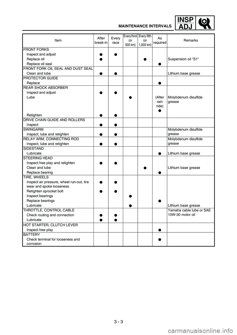
MAINTENANCE INTERVALS
FRONT FORKS
Inspect and adjust
Replace oilSuspension oil “S1”
Replace oil seal
FRONT FORK OIL SEAL AND DUST SEAL
Clean and lubeLithium base grease
PROTECTOR GUIDE
Replace
REAR SHOCK ABSORBER
Inspect and adjust
Lube(After
rain
ride)Molybdenum disulfide
grease
Retighten
DRIVE CHAIN GUIDE AND ROLLERS
Inspect
SWINGARMMolybdenum disulfide
grease
Inspect, lube and retighten
RELAY ARM, CONNECTING ROD Molybdenum disulfide
grease
Inspect, lube and retighten
SIDESTAND
LubricateLithium base grease
STEERING HEAD
Inspect free play and retighten
Clean and lubeLithium base grease
Replace bearing
TIRE, WHEELS
Inspect air pressure, wheel run-out, tire
wear and spoke looseness
Retighten sprocket bolt
Inspect bearings
Replace bearings
LubricateLithium base grease
THROTTLE, CONTROL CABLE Yamaha cable lube or SAE
10W-30 motor oil
Check routing and connection
Lubricate
HOT STARTER, CLUTCH LEVER
Inspect free play
BATTERY
Check terminal for looseness and
corrosionItemAfter
break-inEvery
race
Every third
(or
500 km)Every fifth
(or
1,000 km)As
requiredRemarks
Page 227 of 912
3 - 16
INSP
ADJ
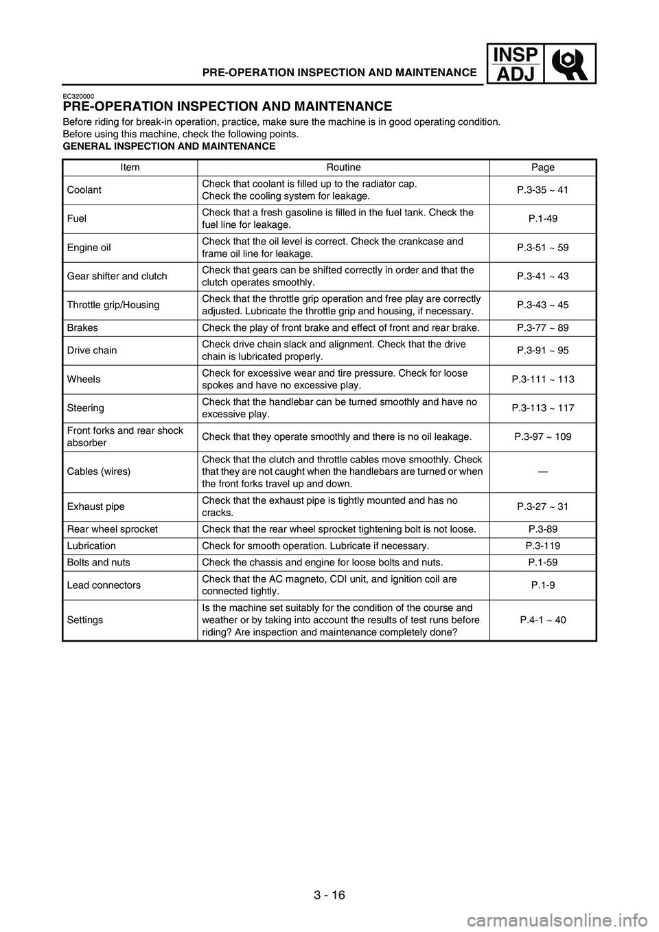
PRE-OPERATION INSPECTION AND MAINTENANCE
EC320000
PRE-OPERATION INSPECTION AND MAINTENANCE
Before riding for break-in operation, practice, make sure the machine is in good operating condition.
Before using this machine, check the following points.
GENERAL INSPECTION AND MAINTENANCE
Item Routine Page
CoolantCheck that coolant is filled up to the radiator cap.
Check the cooling system for leakage.P.3-35 ~ 41
FuelCheck that a fresh gasoline is filled in the fuel tank. Check the
fuel line for leakage.P.1-49
Engine oilCheck that the oil level is correct. Check the crankcase and
frame oil line for leakage.P.3-51 ~ 59
Gear shifter and clutchCheck that gears can be shifted correctly in order and that the
clutch operates smoothly.P.3-41 ~ 43
Throttle grip/HousingCheck that the throttle grip operation and free play are correctly
adjusted. Lubricate the throttle grip and housing, if necessary.P.3-43 ~ 45
Brakes Check the play of front brake and effect of front and rear brake. P.3-77 ~ 89
Drive chainCheck drive chain slack and alignment. Check that the drive
chain is lubricated properly.P.3-91 ~ 95
WheelsCheck for excessive wear and tire pressure. Check for loose
spokes and have no excessive play.P.3-111 ~ 113
SteeringCheck that the handlebar can be turned smoothly and have no
excessive play.P.3-113 ~ 117
Front forks and rear shock
absorberCheck that they operate smoothly and there is no oil leakage. P.3-97 ~ 109
Cables (wires)Check that the clutch and throttle cables move smoothly. Check
that they are not caught when the handlebars are turned or when
the front forks travel up and down.—
Exhaust pipeCheck that the exhaust pipe is tightly mounted and has no
cracks.P.3-27 ~ 31
Rear wheel sprocket Check that the rear wheel sprocket tightening bolt is not loose. P.3-89
Lubrication Check for smooth operation. Lubricate if necessary. P.3-119
Bolts and nuts Check the chassis and engine for loose bolts and nuts. P.1-59
Lead connectorsCheck that the AC magneto, CDI unit, and ignition coil are
connected tightly.P.1-9
SettingsIs the machine set suitably for the condition of the course and
weather or by taking into account the results of test runs before
riding? Are inspection and maintenance completely done?P.4-1 ~ 40
Page 296 of 912
3 - 85
INSP
ADJ
4. Check:
Brake lever operation
A softy or spongy feeling
→
Bleed brake system.
Refer to “BRAKE SYSTEM
AIR BLEEDING” section.
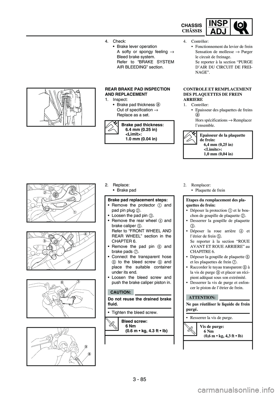
REAR BRAKE PAD INSPECTION
AND REPLACEMENT
1. Inspect:
Brake pad thickness
a
Out of specification
→
Replace as a set.
Brake pad thickness:
6.4 mm (0.25 in)
1.0 mm (0.04 in)
2. Replace:
Brake pad
Brake pad replacement steps:
Remove the protector
1 and
pad pin plug
2.
Loosen the pad pin
3.
Remove the rear wheel
4 and
brake caliper
5.
Refer to “FRONT WHEEL AND
REAR WHEEL” section in the
CHAPTER 6.
Remove the pad pin
6 and
brake pads
7.
Connect the transparent hose
8 to the bleed screw
9 and
place the suitable container
under its end.
Loosen the bleed screw and
push the brake caliper piston in.
CAUTION:
Do not reuse the drained brake
fluid.
Tighten the bleed screw.
T R..
Bleed screw:
6 Nm
(0.6 m kg, 4.3 ft lb)
4. Contrôler:
Fonctionnement du levier de frein
Sensation de mollesse → Purger
le circuit de freinage.
Se reporter à la section “PURGE
D’AIR DU CIRCUIT DE FREI-
NAGE”.
CONTROLE ET REMPLACEMENT
DES PLAQUETTES DE FREIN
ARRIERE
1. Contrôler:
Epaisseur des plaquettes de freins
a
Hors spécifications → Remplacer
l’ensemble.
Epaisseur de la plaquette
de frein:
6,4 mm (0,25 in)
1,0 mm (0,04 in)
2. Remplacer:
Plaquette de frein
Etapes du remplacement des pla-
quettes de frein:
Déposer la protection 1 et le bou-
chon de goupille de plaquette 2.
Desserrer la goupille de plaquette
3.
Déposer la roue arrière 4 et
l’étrier de frein 5.
Se reporter à la section “ROUE
AVANT ET ROUE ARRIERE” au
CHAPITRE 6.
Déposer la goupille de plaquette 6
et les plaquettes de frein 7.
Raccorder le tuyau transparent 8 à
la vis de purge 9 et placer un réci-
pient adéquat sous son extrémité.
Desserrer la vis de purge et enfon-
cer le piston de l’étrier de frein.
ATTENTION:
Ne pas réutiliser le liquide de frein
purgé.
Resserrer la vis de purge.
T R..
Vis de purge:
6 Nm
(0,6 m kg, 4,3 ft lb)
CHASSIS
CHÂSSIS
Page 298 of 912
3 - 87
INSP
ADJ
3. Inspect:
Brake fluid level
Refer to “BRAKE FLUID
LEVEL INSPECTION” section.
4. Check:
Brake pedal operation
A softy or spongy feeling
→
Bleed brake system.
Refer to “BRAKE SYSTEM
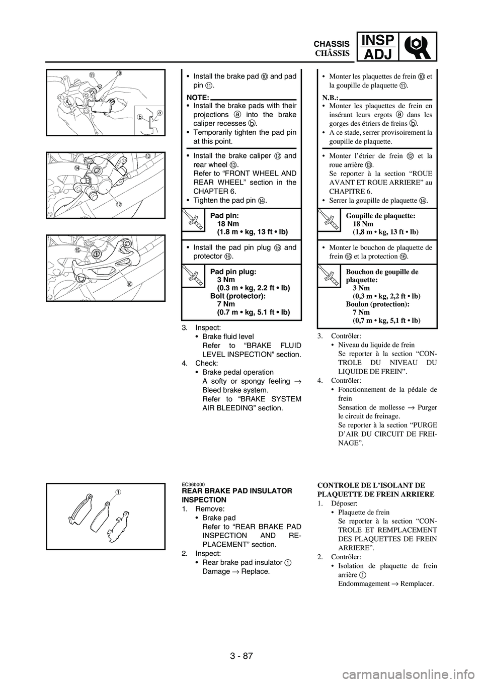
AIR BLEEDING” section. Install the brake pad
0 and pad
pin
A.
NOTE:Install the brake pads with their
projections
a into the brake
caliper recesses
b.
Temporarily tighten the pad pin
at this point.
Install the brake caliper
B and
rear wheel
C.
Refer to “FRONT WHEEL AND
REAR WHEEL” section in the
CHAPTER 6.
Tighten the pad pin
D.
T R..
Pad pin:
18 Nm
(1.8 m kg, 13 ft lb)
Install the pad pin plug
E and
protector
F.
T R..
Pad pin plug:
3 Nm
(0.3 m kg, 2.2 ft lb)
Bolt (protector):
7 Nm
(0.7 m kg, 5.1 ft lb)
EC36b000REAR BRAKE PAD INSULATOR
INSPECTION
1. Remove:
Brake pad
Refer to “REAR BRAKE PAD
INSPECTION AND RE-
PLACEMENT” section.
2. Inspect:
Rear brake pad insulator
1
Damage
→ Replace.
3. Contrôler:
Niveau du liquide de frein
Se reporter à la section “CON-
TROLE DU NIVEAU DU
LIQUIDE DE FREIN”.
4. Contrôler:
Fonctionnement de la pédale de
frein
Sensation de mollesse → Purger
le circuit de freinage.
Se reporter à la section “PURGE
D’AIR DU CIRCUIT DE FREI-
NAGE”. Monter les plaquettes de frein 0 et
la goupille de plaquette A.
N.B.:
Monter les plaquettes de frein en
insérant leurs ergots a dans les
gorges des étriers de freins b.
A ce stade, serrer provisoirement la
goupille de plaquette.
Monter l’étrier de frein B et la
roue arrière C.
Se reporter à la section “ROUE
AVANT ET ROUE ARRIERE” au
CHAPITRE 6.
Serrer la goupille de plaquette D.
T R..
Goupille de plaquette:
18 Nm
(1,8 m kg, 13 ft lb)
Monter le bouchon de plaquette de
frein E et la protection F.
T R..
Bouchon de goupille de
plaquette:
3 Nm
(0,3 m kg, 2,2 ft lb)
Boulon (protection):
7 Nm
(0,7 m kg, 5,1 ft lb)
CONTROLE DE L’ISOLANT DE
PLAQUETTE DE FREIN ARRIERE
1. Déposer:
Plaquette de frein
Se reporter à la section “CON-
TROLE ET REMPLACEMENT
DES PLAQUETTES DE FREIN
ARRIERE”.
2. Contrôler:
Isolation de plaquette de frein
arrière 1
Endommagement → Remplacer.
CHASSIS
CHÂSSIS
Page 300 of 912
3 - 89
INSP
ADJ
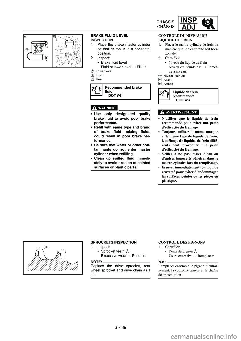
BRAKE FLUID LEVEL
INSPECTION
1. Place the brake master cylinder
so that its top is in a horizontal
position.
2. Inspect:
Brake fluid level
Fluid at lower level
→ Fill up.
aLower level
ÈFront
ÉRear
WARNING
Use only designated quality
brake fluid to avoid poor brake
performance.
Refill with same type and brand
of brake fluid; mixing fluids
could result in poor brake per-
formance.
Be sure that water or other con-
taminants do not enter master
cylinder when refilling.
Clean up spilled fluid immedi-
ately to avoid erosion of painted
surfaces or plastic parts.
Recommended brake
fluid:
DOT #4
ÈÉ
SPROCKETS INSPECTION
1. Inspect:
Sprocket teeth
a
Excessive wear
→ Replace.
NOTE:Replace the drive sprocket, rear
wheel sprocket and drive chain as a
set.
CONTROLE DU NIVEAU DU
LIQUIDE DE FREIN
1. Placer le maître-cylindre de frein de
manière que son extrémité soit hori-
zontale.
2. Contrôler:
Niveau du liquide de frein
Niveau du liquide bas → Remet-
tre à niveau.
a
Niveau inférieur
È
Avant
É
Arrière
AVERTISSEMENT
N’utiliser que le liquide de frein
recommandé pour éviter une perte
d’efficacité du freinage.
Toujours utiliser la même marque
et le même type de liquide de frein;
le mélange de liquides de frein diffé-
rents peut provoquer une perte
d’efficacité du freinage.
Veiller à ne pas laisser d’eau ou
d’autres impuretés pénétrer dans le
maître-cylindre lors du remplissage.
Essuyer immédiatement tout liquide
renversé pour éviter d’endommager
les surfaces peintes ou les pièces en
plastique.
Liquide de frein
recommandé:
DOT n°4
CONTROLE DES PIGNONS
1. Contrôler:
Dents de pignon
a
Usure excessive → Remplacer.
N.B.:
Remplacer ensemble le pignon d’entraî-
nement, la couronne arrière et la chaîne
de transmission.
CHASSIS
CHÂSSIS
Page 304 of 912
3 - 93
INSP
ADJ
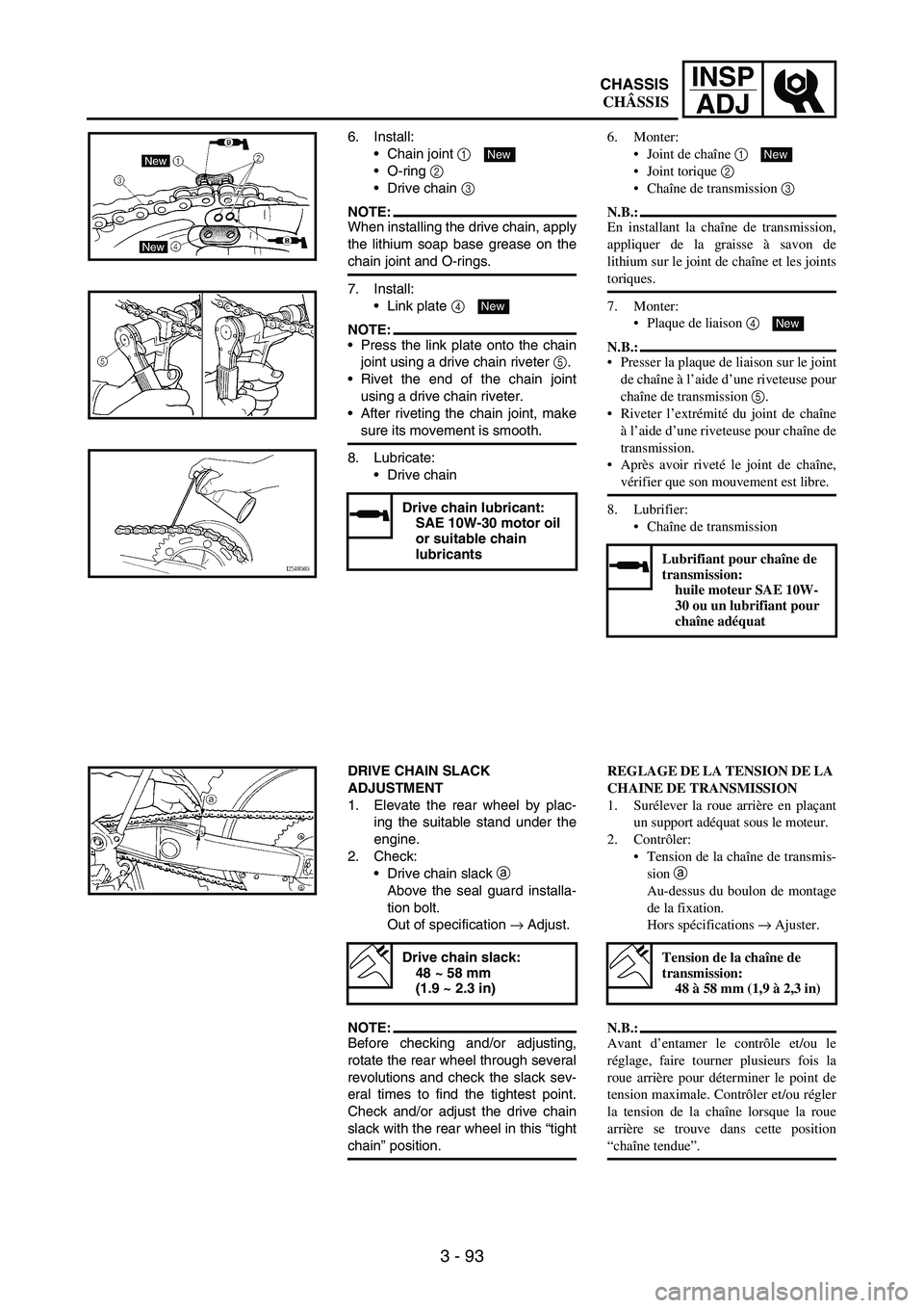
6. Install:
Chain joint
1
O-ring
2
Drive chain
3
NOTE:When installing the drive chain, apply
the lithium soap base grease on the
chain joint and O-rings.
7. Install:
Link plate
4
NOTE:Press the link plate onto the chain
joint using a drive chain riveter
5.
Rivet the end of the chain joint
using a drive chain riveter.
After riveting the chain joint, make
sure its movement is smooth.
8. Lubricate:
Drive chain
Drive chain lubricant:
SAE 10W-30 motor oil
or suitable chain
lubricants
New
New
DRIVE CHAIN SLACK
ADJUSTMENT
1. Elevate the rear wheel by plac-
ing the suitable stand under the
engine.
2. Check:
Drive chain slack
a
Above the seal guard installa-
tion bolt.
Out of specification
→ Adjust.
NOTE:Before checking and/or adjusting,
rotate the rear wheel through several
revolutions and check the slack sev-
eral times to find the tightest point.
Check and/or adjust the drive chain
slack with the rear wheel in this “tight
chain” position.
Drive chain slack:
48 ~ 58 mm
(1.9 ~ 2.3 in)
6. Monter:
Joint de chaîne 1
Joint torique 2
Chaîne de transmission 3
N.B.:
En installant la chaîne de transmission,
appliquer de la graisse à savon de
lithium sur le joint de chaîne et les joints
toriques.
7. Monter:
Plaque de liaison 4
N.B.:
Presser la plaque de liaison sur le joint
de chaîne à l’aide d’une riveteuse pour
chaîne de transmission 5.
Riveter l’extrémité du joint de chaîne
à l’aide d’une riveteuse pour chaîne de
transmission.
Après avoir riveté le joint de chaîne,
vérifier que son mouvement est libre.
8. Lubrifier:
Chaîne de transmission
Lubrifiant pour chaîne de
transmission:
huile moteur SAE 10W-
30 ou un lubrifiant pour
chaîne adéquat
New
New
REGLAGE DE LA TENSION DE LA
CHAINE DE TRANSMISSION
1. Surélever la roue arrière en plaçant
un support adéquat sous le moteur.
2. Contrôler:
Tension de la chaîne de transmis-
sion a
Au-dessus du boulon de montage
de la fixation.
Hors spécifications → Ajuster.
N.B.:
Avant d’entamer le contrôle et/ou le
réglage, faire tourner plusieurs fois la
roue arrière pour déterminer le point de
tension maximale. Contrôler et/ou régler
la tension de la chaîne lorsque la roue
arrière se trouve dans cette position
“chaîne tendue”.
Tension de la chaîne de
transmission:
48 à 58 mm (1,9 à 2,3 in)
CHASSIS
CHÂSSIS
Page 306 of 912
3 - 95
INSP
ADJ
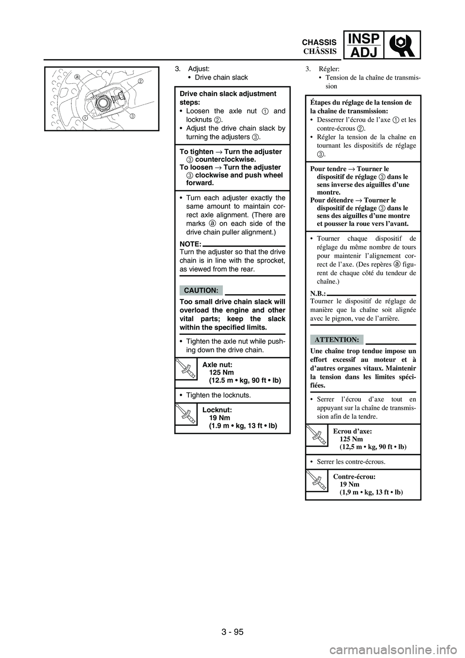
3. Adjust:
Drive chain slack
Drive chain slack adjustment
steps:
Loosen the axle nut
1 and
locknuts
2.
Adjust the drive chain slack by
turning the adjusters
3.
To tighten → Turn the adjuster
3 counterclockwise.
To loosen → Turn the adjuster
3 clockwise and push wheel
forward.
Turn each adjuster exactly the
same amount to maintain cor-
rect axle alignment. (There are
marks
a on each side of the
drive chain puller alignment.)
NOTE:Turn the adjuster so that the drive
chain is in line with the sprocket,
as viewed from the rear.
CAUTION:
Too small drive chain slack will
overload the engine and other
vital parts; keep the slack
within the specified limits.
Tighten the axle nut while push-
ing down the drive chain.
T R..
Axle nut:
125 Nm
(12.5 m kg, 90 ft lb)
Tighten the locknuts.
T R..
Locknut:
19 Nm
(1.9 m kg, 13 ft lb)
3. Régler:
Tension de la chaîne de transmis-
sion
Étapes du réglage de la tension de
la chaîne de transmission:
Desserrer l’écrou de l’axe 1 et les
contre-écrous 2.
Régler la tension de la chaîne en
tournant les dispositifs de réglage
3.
Pour tendre → Tourner le
dispositif de réglage 3 dans le
sens inverse des aiguilles d’une
montre.
Pour détendre → Tourner le
dispositif de réglage 3 dans le
sens des aiguilles d’une montre
et pousser la roue vers l’avant.
Tourner chaque dispositif de
réglage du même nombre de tours
pour maintenir l’alignement cor-
rect de l’axe. (Des repères a figu-
rent de chaque côté du tendeur de
chaîne.)
N.B.:
Tourner le dispositif de réglage de
manière que la chaîne soit alignée
avec le pignon, vue de l’arrière.
ATTENTION:
Une chaîne trop tendue impose un
effort excessif au moteur et à
d’autres organes vitaux. Maintenir
la tension dans les limites spéci-
fiées.
Serrer l’écrou d’axe tout en
appuyant sur la chaîne de transmis-
sion afin de la tendre.
T R..
Ecrou d’axe:
125 Nm
(12,5 m kg, 90 ft lb)
Serrer les contre-écrous.
T R..
Contre-écrou:
19 Nm
(1,9 m kg, 13 ft lb)
CHASSIS
CHÂSSIS
Page 308 of 912
3 - 97
INSP
ADJ
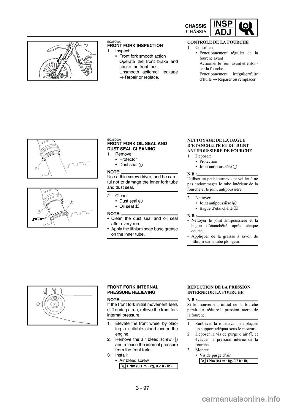
EC36C000FRONT FORK INSPECTION
1. Inspect:
Front fork smooth action
Operate the front brake and
stroke the front fork.
Unsmooth action/oil leakage
→ Repair or replace.
EC36D001FRONT FORK OIL SEAL AND
DUST SEAL CLEANING
1. Remove:
Protector
Dust seal
1
NOTE:Use a thin screw driver, and be care-
ful not to damage the inner fork tube
and dust seal.
2. Clean:
Dust seal
a
Oil seal
b
NOTE:Clean the dust seal and oil seal
after every run.
Apply the lithium soap base grease
on the inner tube.
FRONT FORK INTERNAL
PRESSURE RELIEVING
NOTE:If the front fork initial movement feels
stiff during a run, relieve the front fork
internal pressure.
1. Elevate the front wheel by plac-
ing a suitable stand under the
engine.
2. Remove the air bleed screw
1
and release the internal pressure
from the front fork.
3. Install:
Air bleed screw
T R..1 Nm (0.1 m · kg, 0.7 ft · lb)
CONTROLE DE LA FOURCHE
1. Contrôler:
Fonctionnement régulier de la
fourche avant
Actionner le frein avant et enfon-
cer la fourche.
Fonctionnement irrégulier/fuite
d’huile → Réparer ou remplacer.
NETTOYAGE DE LA BAGUE
D’ETANCHEITE ET DU JOINT
ANTIPOUSSIERE DE FOURCHE
1. Déposer:
Protection
Joint antipoussière 1
N.B.:
Utiliser un petit tournevis et veiller à ne
pas endommager le tube intérieur de la
fourche et le joint antipoussière.
2. Nettoyer:
Joint antipoussière a
Bague d’étanchéité b
N.B.:
Nettoyer le joint antipoussière et la
bague d’étanchéité après chaque
course.
Appliquer de la graisse à savon de
lithium sur le tube plongeur.
REDUCTION DE LA PRESSION
INTERNE DE LA FOURCHE
N.B.:
Si le mouvement initial de la fourche
paraît dur, réduire la pression interne de
la fourche.
1. Surélever la roue avant en plaçant
un support adéquat sous le moteur.
2. Déposer la vis de purge d’air 1 et
évacuer la pression interne de la
fourche.
3. Monter:
Vis de purge d’air
T R..1 Nm (0,1 m · kg, 0,7 ft · lb)
CHASSIS
CHÂSSIS CHASSIS
Page 314 of 912
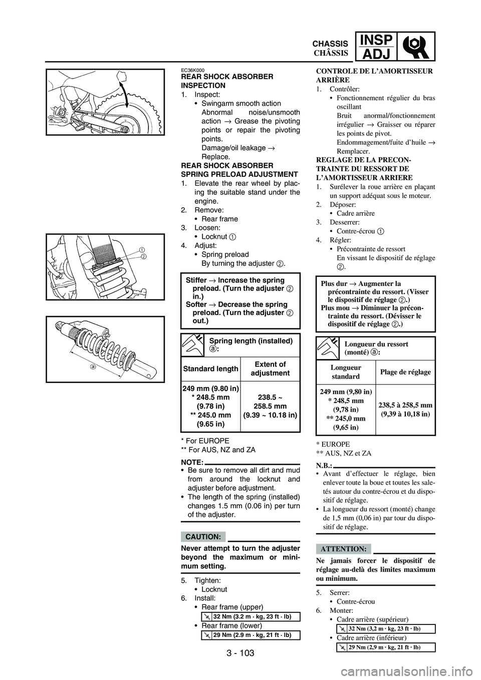
3 - 103
INSP
ADJ
EC36K000REAR SHOCK ABSORBER
INSPECTION
1. Inspect:
Swingarm smooth action
Abnormal noise/unsmooth
action
→ Grease the pivoting
points or repair the pivoting
points.
Damage/oil leakage
→
Replace.
REAR SHOCK ABSORBER
SPRING PRELOAD ADJUSTMENT
1. Elevate the rear wheel by plac-
ing the suitable stand under the
engine.
2. Remove:
Rear frame
3. Loosen:
Locknut
1
4. Adjust:
Spring preload
By turning the adjuster
2.
* For EUROPE
** For AUS, NZ and ZA
NOTE:Be sure to remove all dirt and mud
from around the locknut and
adjuster before adjustment.
The length of the spring (installed)
changes 1.5 mm (0.06 in) per turn
of the adjuster.
CAUTION:
Never attempt to turn the adjuster
beyond the maximum or mini-
mum setting.
5. Tighten:
Locknut
6. Install:
Rear frame (upper)
Rear frame (lower) Stiffer → Increase the spring
preload. (Turn the adjuster 2
in.)
Softer → Decrease the spring
preload. (Turn the adjuster 2
out.)
Spring length (installed)
a:
Standard lengthExtent of
adjustment
249 mm (9.80 in)
* 248.5 mm
(9.78 in)
** 245.0 mm
(9.65 in)238.5 ~
258.5 mm
(9.39 ~ 10.18 in)
T R..32 Nm (3.2 m · kg, 23 ft · lb)
T R..29 Nm (2.9 m · kg, 21 ft · lb)
CONTROLE DE L’AMORTISSEUR
ARRIÈRE
1. Contrôler:
Fonctionnement régulier du bras
oscillant
Bruit anormal/fonctionnement
irrégulier → Graisser ou réparer
les points de pivot.
Endommagement/fuite d’huile →
Remplacer.
REGLAGE DE LA PRECON-
TRAINTE DU RESSORT DE
L’AMORTISSEUR ARRIERE
1. Surélever la roue arrière en plaçant
un support adéquat sous le moteur.
2. Déposer:
Cadre arrière
3. Desserrer:
Contre-écrou 1
4. Régler:
Précontrainte de ressort
En vissant le dispositif de réglage
2.
* EUROPE
** AUS, NZ et ZA
N.B.:
Avant d’effectuer le réglage, bien
enlever toute la boue et toutes les sale-
tés autour du contre-écrou et du dispo-
sitif de réglage.
La longueur du ressort (monté) change
de 1,5 mm (0,06 in) par tour du dispo-
sitif de réglage.
ATTENTION:
Ne jamais forcer le dispositif de
réglage au-delà des limites maximum
ou minimum.
5. Serrer:
Contre-écrou
6. Monter:
Cadre arrière (supérieur)
Cadre arrière (inférieur) Plus dur → Augmenter la
précontrainte du ressort. (Visser
le dispositif de réglage 2.)
Plus mou → Diminuer la précon-
trainte du ressort. (Dévisser le
dispositif de réglage 2.)
Longueur du ressort
(monté) a:
Longueur
standardPlage de réglage
249 mm (9,80 in)
* 248,5 mm
(9,78 in)
** 245,0 mm
(9,65 in)238,5 à 258,5 mm
(9,39 à 10,18 in)
T R..32 Nm (3,2 m · kg, 23 ft · lb)
T R..29 Nm (2,9 m · kg, 21 ft · lb)
CHASSIS
CHÂSSIS