engine coolant YAMAHA WR 250F 2007 Owners Manual
[x] Cancel search | Manufacturer: YAMAHA, Model Year: 2007, Model line: WR 250F, Model: YAMAHA WR 250F 2007Pages: 912, PDF Size: 23.95 MB
Page 26 of 912
1 - 1
GEN
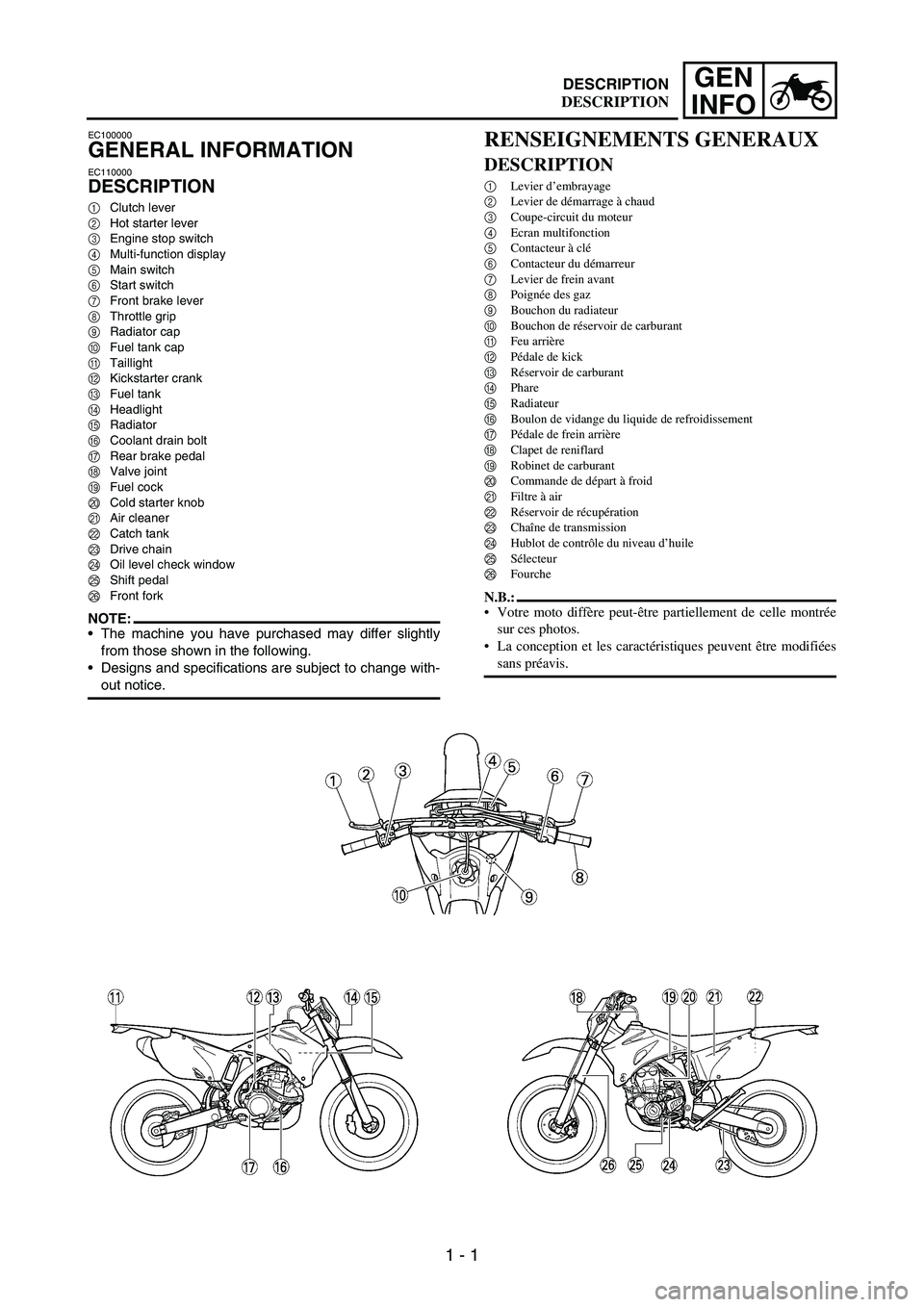
INFODESCRIPTION
EC100000
GENERAL INFORMATION
EC110000
DESCRIPTION
1Clutch lever
2Hot starter lever
3Engine stop switch
4Multi-function display
5Main switch
6Start switch
7Front brake lever
8Throttle grip
9Radiator cap
0Fuel tank cap
ATaillight
BKickstarter crank
CFuel tank
DHeadlight
ERadiator
FCoolant drain bolt
GRear brake pedal
HValve joint
IFuel cock
JCold starter knob
KAir cleaner
LCatch tank
MDrive chain
NOil level check window
OShift pedal
PFront fork
NOTE:The machine you have purchased may differ slightly
from those shown in the following.
Designs and specifications are subject to change with-
out notice.
RENSEIGNEMENTS GENERAUX
DESCRIPTION
1Levier d’embrayage
2Levier de démarrage à chaud
3Coupe-circuit du moteur
4Ecran multifonction
5Contacteur à clé
6Contacteur du démarreur
7Levier de frein avant
8Poignée des gaz
9Bouchon du radiateur
0Bouchon de réservoir de carburant
AFeu arrière
BPédale de kick
CRéservoir de carburant
DPhare
ERadiateur
FBoulon de vidange du liquide de refroidissement
GPédale de frein arrière
HClapet de reniflard
IRobinet de carburant
JCommande de départ à froid
KFiltre à air
LRéservoir de récupération
MChaîne de transmission
NHublot de contrôle du niveau d’huile
OSélecteur
PFourche
N.B.:
Votre moto diffère peut-être partiellement de celle montrée
sur ces photos.
La conception et les caractéristiques peuvent être modifiées
sans préavis.
DESCRIPTION
Page 78 of 912

1 - 53
GEN
INFO
1. Inspect the coolant level.
2. Turn the fuel cock to “ON”.
3. Push on the main switch to “ON”.
4. Shift the transmission into neu-
tral.
5. Fully open the cold starter knob
1.
6. Start the engine by pushing the
start switch or by kicking the
kickstarter crank.
NOTE:If the engine fails to start by pushing
the start switch, release the switch,
wait a few seconds, and then try
again. Each starting attempt should
be as short as possible to preserve
the battery. Do not crank the engine
more than 10 seconds on any one
attempt. If the engine does not start
with the starter motor, try using the
kickstarter crank.
WARNING
If the starter motor will not turn
when pushing the start switch,
stop pushing it immediately and
kick start the engine in order to
avoid the load on the motor.
Do not open the throttle while
kicking the kickstarter crank.
Otherwise, the kickstarter crank
may kick back.
1
7. Return the cold starter knob to
its original position and run the
engine at 3,000 ~ 5,000 r/min for
1 or 2 minutes.
NOTE:Since this model is equipped with an
accelerator pump, if the engine is
raced (the throttle opened and
closed), the air/fuel mixture will be
too rich and the engine may stall.
Also unlike a two-stroke engine, this
model can idle.
CAUTION:
Do not warm up the engine for
extended periods of time.1. Contrôler le niveau de liquide de
refroidissement.
2. Placer le robinet de carburant en
position “ON”.
3. Tourner le contacteur à clé sur
“ON”.
4. Mettre la boîte au point mort.
5. Tirer complètement la commande
de départ à froid 1.
6. Démarrer le moteur en appuyant sur
le contacteur du démarreur ou en
actionnant le kick.
N.B.:
Si le moteur ne répond pas au contacteur
du démarreur, relâcher ce dernier, atten-
dre quelques secondes et essayer à nou-
veau. Chaque tentative de démarrage
doit être aussi brève que possible pour
économiser la batterie. Ne pas lancer le
moteur pendant plus de 10 secondes à
chaque tentative. S’il est impossible de
démarrer le moteur à l’aide du démar-
reur, essayer le démarrage au kick.
AVERTISSEMENT
Si le démarreur ne répond pas au
contacteur du démarreur, arrêter
immédiatement d’appuyer sur ce
dernier et démarrer au kick pour
éviter de trop solliciter le moteur.
Ne pas ouvrir le papillon tout en
démarrant au kick car ce dernier
risque de revenir brutalement.
7. Repousser la commande de départ à
froid dans sa position d’origine et
faire tourner le moteur à 3.000 à
5.000 tr/min pendant 1 ou 2 minu-
tes.
N.B.:
Ce modèle étant équipé d’une pompe de
reprise, si le moteur est emballé (ouver-
ture et fermeture du papillon), le
mélange air/carburant sera trop riche et
le moteur risque de caler. A la différence
d’un moteur deux temps, par ailleurs, ce
modèle peut tourner au ralenti.
ATTENTION:
Ne pas faire chauffer le moteur plus
longtemps que nécessaire.
STARTING AND BREAK-IN
MISE EN MARCHE ET RODAGE
Page 95 of 912
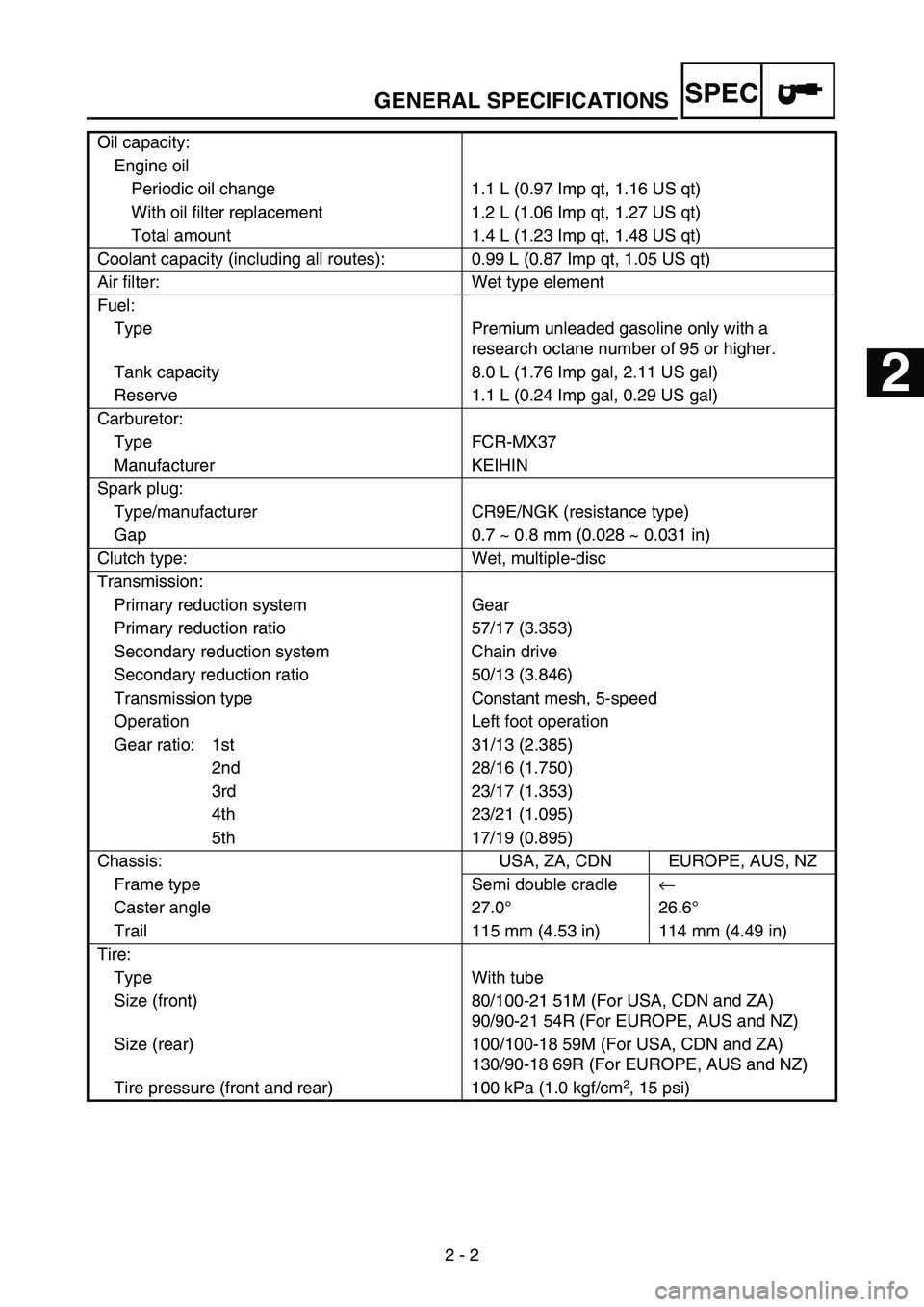
GENERAL SPECIFICATIONS
2 - 2
SPEC
Oil capacity:
Engine oil
Periodic oil change 1.1 L (0.97 Imp qt, 1.16 US qt)
With oil filter replacement 1.2 L (1.06 Imp qt, 1.27 US qt)
Total amount 1.4 L (1.23 Imp qt, 1.48 US qt)
Coolant capacity (including all routes): 0.99 L (0.87 Imp qt, 1.05 US qt)
Air filter: Wet type element
Fuel:
Type Premium unleaded gasoline only with a
research octane number of 95 or higher.
Tank capacity 8.0 L (1.76 Imp gal, 2.11 US gal)
Reserve 1.1 L (0.24 Imp gal, 0.29 US gal)
Carburetor:
Type FCR-MX37
Manufacturer KEIHIN
Spark plug:
Type/manufacturer CR9E/NGK (resistance type)
Gap 0.7 ~ 0.8 mm (0.028 ~ 0.031 in)
Clutch type: Wet, multiple-disc
Transmission:
Primary reduction system Gear
Primary reduction ratio 57/17 (3.353)
Secondary reduction system Chain drive
Secondary reduction ratio 50/13 (3.846)
Transmission type Constant mesh, 5-speed
Operation Left foot operation
Gear ratio: 1st 31/13 (2.385)
2nd 28/16 (1.750)
3rd 23/17 (1.353)
4th 23/21 (1.095)
5th 17/19 (0.895)
Chassis: USA, ZA, CDN EUROPE, AUS, NZ
Frame type Semi double cradle←
Caster angle 27.0°26.6°
Trail 115 mm (4.53 in) 114 mm (4.49 in)
Tire:
Type With tube
Size (front) 80/100-21 51M (For USA, CDN and ZA)
90/90-21 54R (For EUROPE, AUS and NZ)
Size (rear) 100/100-18 59M (For USA, CDN and ZA)
130/90-18 69R (For EUROPE, AUS and NZ)
Tire pressure (front and rear) 100 kPa (1.0 kgf/cm
2, 15 psi)
1
2
3
4
5
6
7
Page 227 of 912
3 - 16
INSP
ADJ
PRE-OPERATION INSPECTION AND MAINTENANCE
EC320000
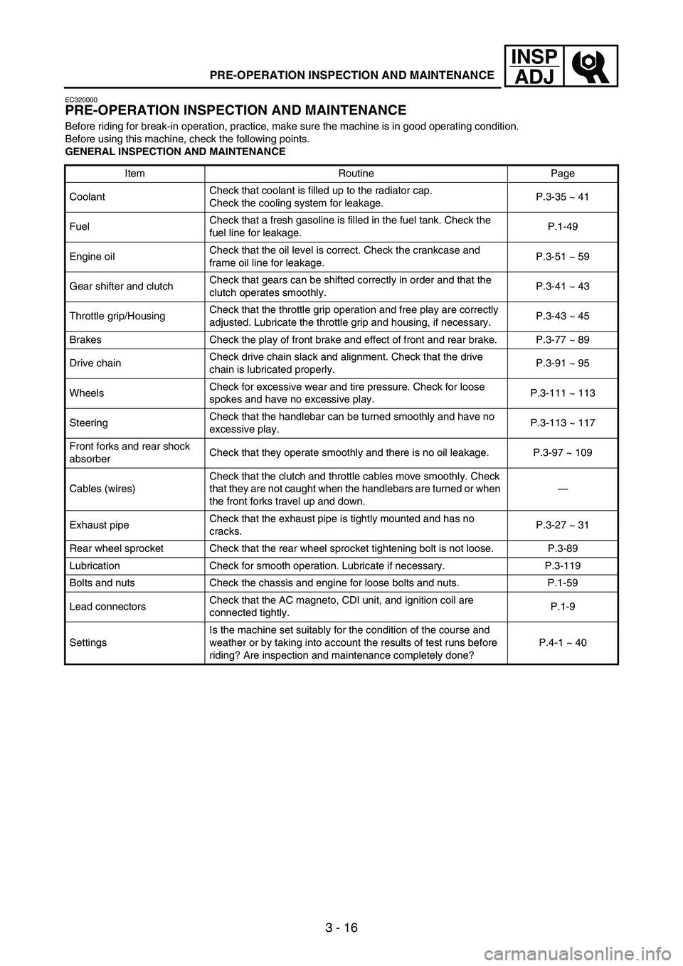
PRE-OPERATION INSPECTION AND MAINTENANCE
Before riding for break-in operation, practice, make sure the machine is in good operating condition.
Before using this machine, check the following points.
GENERAL INSPECTION AND MAINTENANCE
Item Routine Page
CoolantCheck that coolant is filled up to the radiator cap.
Check the cooling system for leakage.P.3-35 ~ 41
FuelCheck that a fresh gasoline is filled in the fuel tank. Check the
fuel line for leakage.P.1-49
Engine oilCheck that the oil level is correct. Check the crankcase and
frame oil line for leakage.P.3-51 ~ 59
Gear shifter and clutchCheck that gears can be shifted correctly in order and that the
clutch operates smoothly.P.3-41 ~ 43
Throttle grip/HousingCheck that the throttle grip operation and free play are correctly
adjusted. Lubricate the throttle grip and housing, if necessary.P.3-43 ~ 45
Brakes Check the play of front brake and effect of front and rear brake. P.3-77 ~ 89
Drive chainCheck drive chain slack and alignment. Check that the drive
chain is lubricated properly.P.3-91 ~ 95
WheelsCheck for excessive wear and tire pressure. Check for loose
spokes and have no excessive play.P.3-111 ~ 113
SteeringCheck that the handlebar can be turned smoothly and have no
excessive play.P.3-113 ~ 117
Front forks and rear shock
absorberCheck that they operate smoothly and there is no oil leakage. P.3-97 ~ 109
Cables (wires)Check that the clutch and throttle cables move smoothly. Check
that they are not caught when the handlebars are turned or when
the front forks travel up and down.—
Exhaust pipeCheck that the exhaust pipe is tightly mounted and has no
cracks.P.3-27 ~ 31
Rear wheel sprocket Check that the rear wheel sprocket tightening bolt is not loose. P.3-89
Lubrication Check for smooth operation. Lubricate if necessary. P.3-119
Bolts and nuts Check the chassis and engine for loose bolts and nuts. P.1-59
Lead connectorsCheck that the AC magneto, CDI unit, and ignition coil are
connected tightly.P.1-9
SettingsIs the machine set suitably for the condition of the course and
weather or by taking into account the results of test runs before
riding? Are inspection and maintenance completely done?P.4-1 ~ 40
Page 244 of 912
3 - 33
INSP
ADJ
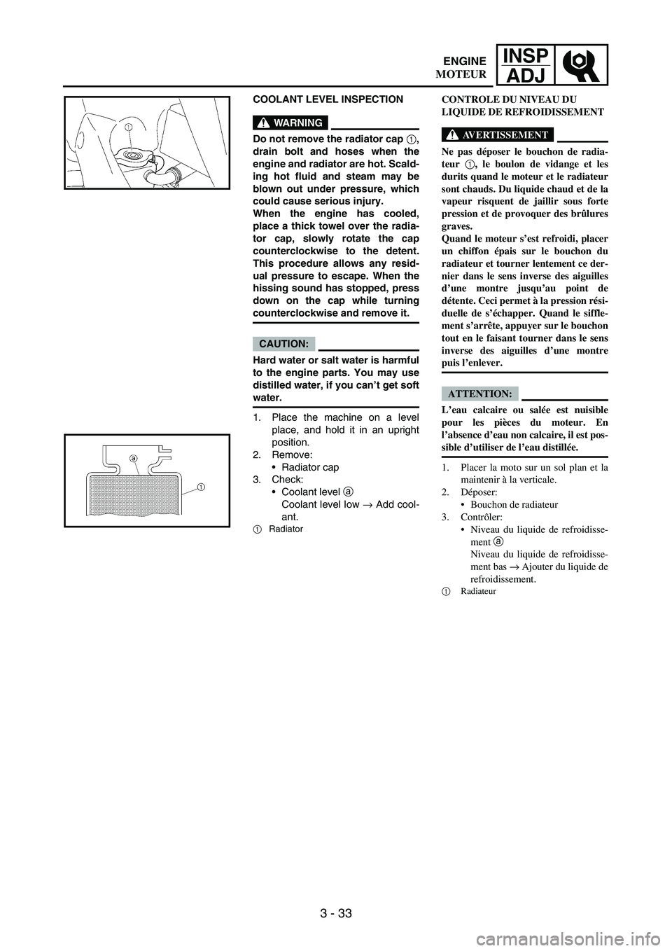
COOLANT LEVEL INSPECTION
WARNING
Do not remove the radiator cap 1,
drain bolt and hoses when the
engine and radiator are hot. Scald-
ing hot fluid and steam may be
blown out under pressure, which
could cause serious injury.
When the engine has cooled,
place a thick towel over the radia-
tor cap, slowly rotate the cap
counterclockwise to the detent.
This procedure allows any resid-
ual pressure to escape. When the
hissing sound has stopped, press
down on the cap while turning
counterclockwise and remove it.
CAUTION:
Hard water or salt water is harmful
to the engine parts. You may use
distilled water, if you can’t get soft
water.
1. Place the machine on a level
place, and hold it in an upright
position.
2. Remove:
Radiator cap
3. Check:
Coolant level
a
Coolant level low
→ Add cool-
ant.
1Radiator
CONTROLE DU NIVEAU DU
LIQUIDE DE REFROIDISSEMENT
AVERTISSEMENT
Ne pas déposer le bouchon de radia-
teur 1, le boulon de vidange et les
durits quand le moteur et le radiateur
sont chauds. Du liquide chaud et de la
vapeur risquent de jaillir sous forte
pression et de provoquer des brûlures
graves.
Quand le moteur s’est refroidi, placer
un chiffon épais sur le bouchon du
radiateur et tourner lentement ce der-
nier dans le sens inverse des aiguilles
d’une montre jusqu’au point de
détente. Ceci permet à la pression rési-
duelle de s’échapper. Quand le siffle-
ment s’arrête, appuyer sur le bouchon
tout en le faisant tourner dans le sens
inverse des aiguilles d’une montre
puis l’enlever.
ATTENTION:
L’eau calcaire ou salée est nuisible
pour les pièces du moteur. En
l’absence d’eau non calcaire, il est pos-
sible d’utiliser de l’eau distillée.
1. Placer la moto sur un sol plan et la
maintenir à la verticale.
2. Déposer:
Bouchon de radiateur
3. Contrôler:
Niveau du liquide de refroidisse-
ment a
Niveau du liquide de refroidisse-
ment bas → Ajouter du liquide de
refroidissement.
1
Radiateur
ENGINE
MOTEUR
Page 246 of 912
3 - 35
INSP
ADJ
COOLANT REPLACEMENT
WARNING
Do not remove the radiator cap
when the engine is hot.
CAUTION:
Take care so that coolant does not
splash on painted surfaces. If it
splashes, wash it away with water.
1. Place a container under the
engine.
2. Remove:
Seat
Left side cover
3. Remove the catch tank hose
from the catch tank and drain the
tank of its coolant.
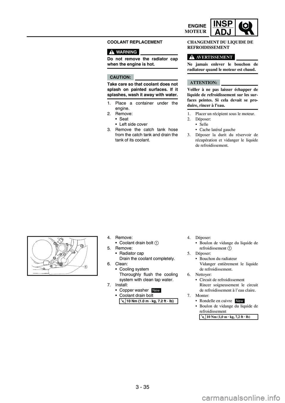
4. Remove:
Coolant drain bolt
1
5. Remove:
Radiator cap
Drain the coolant completely.
6. Clean:
Cooling system
Thoroughly flush the cooling
system with clean tap water.
7. Install:
Copper washer
Coolant drain bolt
T R..10 Nm (1.0 m · kg, 7.2 ft · lb)
New
CHANGEMENT DU LIQUIDE DE
REFROIDISSEMENT
AVERTISSEMENT
Ne jamais enlever le bouchon de
radiateur quand le moteur est chaud.
ATTENTION:
Veiller à ne pas laisser échapper de
liquide de refroidissement sur les sur-
faces peintes. Si cela devait se pro-
duire, rincer à l’eau.
1. Placer un récipient sous le moteur.
2. Déposer:
Selle
Cache latéral gauche
3. Déposer la durit du réservoir de
récupération et vidanger le liquide
de refroidissement.
4. Déposer:
Boulon de vidange du liquide de
refroidissement 1
5. Déposer:
Bouchon du radiateur
Vidanger entièrement le liquide
de refroidissement.
6. Nettoyer:
Circuit de refroidissement
Rincer soigneusement le circuit
de refroidissement à l’eau claire.
7. Monter:
Rondelle en cuivre
Boulon de vidange du liquide de
refroidissement
T R..10 Nm (1,0 m · kg, 7,2 ft · lb)
New
ENGINE
MOTEUR
Page 248 of 912
3 - 37
INSP
ADJ
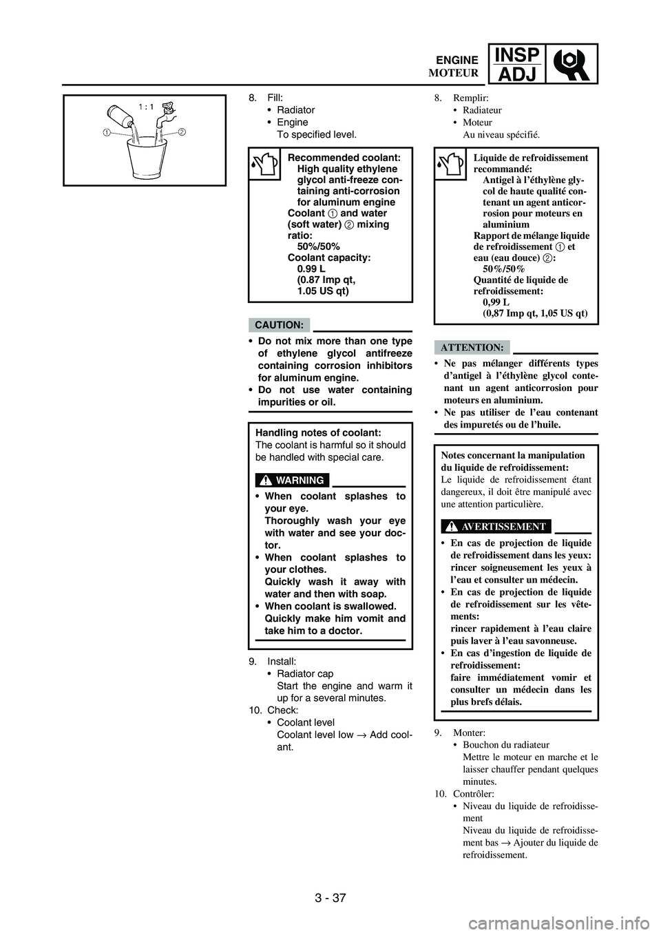
8. Fill:
Radiator
Engine
To specified level.
CAUTION:
Do not mix more than one type
of ethylene glycol antifreeze
containing corrosion inhibitors
for aluminum engine.
Do not use water containing
impurities or oil.
9. Install:
Radiator cap
Start the engine and warm it
up for a several minutes.
10. Check:
Coolant level
Coolant level low
→ Add cool-
ant.
Recommended coolant:
High quality ethylene
glycol anti-freeze con-
taining anti-corrosion
for aluminum engine
Coolant 1 and water
(soft water) 2 mixing
ratio:
50%/50%
Coolant capacity:
0.99 L
(0.87 Imp qt,
1.05 US qt)
Handling notes of coolant:
The coolant is harmful so it should
be handled with special care.
WARNING
When coolant splashes to
your eye.
Thoroughly wash your eye
with water and see your doc-
tor.
When coolant splashes to
your clothes.
Quickly wash it away with
water and then with soap.
When coolant is swallowed.
Quickly make him vomit and
take him to a doctor.
8. Remplir:
Radiateur
Moteur
Au niveau spécifié.
ATTENTION:
Ne pas mélanger différents types
d’antigel à l’éthylène glycol conte-
nant un agent anticorrosion pour
moteurs en aluminium.
Ne pas utiliser de l’eau contenant
des impuretés ou de l’huile.
9. Monter:
Bouchon du radiateur
Mettre le moteur en marche et le
laisser chauffer pendant quelques
minutes.
10. Contrôler:
Niveau du liquide de refroidisse-
ment
Niveau du liquide de refroidisse-
ment bas → Ajouter du liquide de
refroidissement.
Liquide de refroidissement
recommandé:
Antigel à l’éthylène gly-
col de haute qualité con-
tenant un agent anticor-
rosion pour moteurs en
aluminium
Rapport de mélange liquide
de refroidissement 1 et
eau (eau douce) 2:
50%/50%
Quantité de liquide de
refroidissement:
0,99 L
(0,87 Imp qt, 1,05 US qt)
Notes concernant la manipulation
du liquide de refroidissement:
Le liquide de refroidissement étant
dangereux, il doit être manipulé avec
une attention particulière.
AVERTISSEMENT
En cas de projection de liquide
de refroidissement dans les yeux:
rincer soigneusement les yeux à
l’eau et consulter un médecin.
En cas de projection de liquide
de refroidissement sur les vête-
ments:
rincer rapidement à l’eau claire
puis laver à l’eau savonneuse.
En cas d’ingestion de liquide de
refroidissement:
faire immédiatement vomir et
consulter un médecin dans les
plus brefs délais.
ENGINE
MOTEUR
Page 252 of 912
3 - 41
INSP
ADJ
COOLING SYSTEM INSPECTION
1. Inspect:
Coolant level
2. Attach:
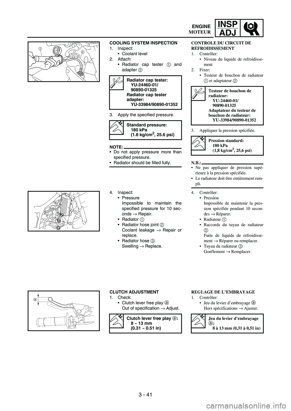
Radiator cap tester
1 and
adapter
2
3. Apply the specified pressure.
NOTE:Do not apply pressure more than
specified pressure.
Radiator should be filled fully.
Radiator cap tester:
YU-24460-01/
90890-01325
Radiator cap tester
adapter:
YU-33984/90890-01352
Standard pressure:
180 kPa
(1.8 kg/cm
2, 25.6 psi)
4. Inspect:
Pressure
Impossible to maintain the
specified pressure for 10 sec-
onds
→ Repair.
Radiator
1
Radiator hose joint
2
Coolant leakage
→ Repair or
replace.
Radiator hose
3
Swelling
→ Replace.
CLUTCH ADJUSTMENT
1. Check:
Clutch lever free play
a
Out of specification
→ Adjust.
Clutch lever free play a:
8 ~ 13 mm
(0.31 ~ 0.51 in)
CONTROLE DU CIRCUIT DE
REFROIDISSEMENT
1. Contrôler:
Niveau du liquide de refroidisse-
ment
2. Fixer:
Testeur de bouchon de radiateur
1 et adaptateur 2
3. Appliquer la pression spécifiée.
N.B.:
Ne pas appliquer de pression supé-
rieure à la pression spécifiée.
Le radiateur doit être entièrement rem-
pli.
Testeur de bouchon de
radiateur:
YU-24460-01/
90890-01325
Adaptateur du testeur de
bouchon de radiateur:
YU-33984/90890-01352
Pression standard:
180 kPa
(1,8 kg/cm
2, 25,6 psi)
4. Contrôler:
Pression
Impossible de maintenir la pres-
sion spécifiée pendant 10 secon-
des → Réparer.
Radiateur 1
Raccords du tuyau de radiateur
2
Fuite de liquide de refroidisse-
ment → Réparer ou remplacer.
Tuyau du radiateur 3
Gonflement → Remplacer.
REGLAGE DE L’EMBRAYAGE
1. Contrôler:
Jeu du levier d’embrayage a
Hors spécifications → Ajuster.
Jeu du levier d’embrayage
a:
8 à 13 mm (0,31 à 0,51 in)
ENGINE
MOTEUR
Page 272 of 912
3 - 61
INSP
ADJ
VALVE CLEARANCE INSPECTION
AND ADJUSTMENT
NOTE:This section is intended for those
who have basic knowledge and skill
concerning the servicing of Yamaha
motorcycles (e.g., Yamaha dealers,
service engineers, etc.) Those who
have little knowledge and skill con-
cerning servicing are requested not
to undertake inspection, adjustment,
disassembly, or reassembly only by
reference to this manual. It may lead
to servicing trouble and mechanical
damage.
NOTE:The valve clearance should be
adjusted when the engine is cool to
the touch.
The piston must be at Top Dead
Center (T.D.C.) on compression
stroke to check or adjust the valve
clearance.
1. Remove:
Seat
Fuel tank
Refer to “SEAT, FUEL TANK
AND SIDE COVERS” section.
2. Drain:
Coolant
Refer to “COOLANT
REPLACEMENT” section.
3. Remove:
Right radiator
Refer to “RADIATOR” section
in the CHAPTER 5.
Carburetor
Refer to “CARBURETOR”
section in the CHAPTER 5.
Spark plug
Upper engine bracket
Cylinder head cover
Refer to “CAMSHAFTS” sec-
tion in the CHAPTER 5.
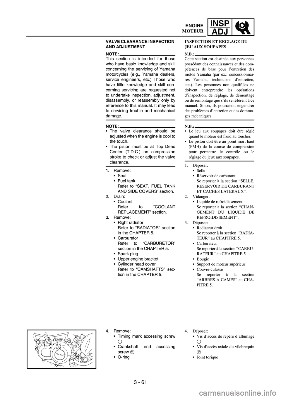
4. Remove:
Timing mark accessing screw
1
Crankshaft end accessing
screw
2
O-ring
INSPECTION ET REGLAGE DU
JEU AUX SOUPAPES
N.B.:
Cette section est destinée aux personnes
possédant des connaissances et des com-
pétences de base pour l’entretien des
motos Yamaha (par ex.: concessionnai-
res Yamaha, techniciens d’entretien,
etc.). Les personnes non qualifiées ne
doivent entreprendre les opérations
d’inspection, de réglage, de démontage
ou de remontage que s’ils se réfèrent à ce
manuel. Sinon, ils pourraient engendrer
des problèmes d’entretien et des domma-
ges mécaniques.
N.B.:
Le jeu aux soupapes doit être réglé
quand le moteur est froid au toucher.
Le piston doit être au point mort haut
(PMH) de la course de compression
pour permettre le contrôle ou le
réglage du jeux aux soupapes.
1. Déposer:
Selle
Réservoir de carburant
Se reporter à la section “SELLE,
RESERVOIR DE CARBURANT
ET CACHES LATERAUX”.
2. Vidanger:
Liquide de refroidissement
Se reporter à la section “CHAN-
GEMENT DU LIQUIDE DE
REFROIDISSEMENT”.
3. Déposer:
Radiateur droit
Se reporter à la section “RADIA-
TEUR” au CHAPITRE 5.
Carburateur
Se reporter à la section “CARBU-
RATEUR” au CHAPITRE 5.
Bougie
Support de moteur supérieur
Couvre-culasse
Se reporter à la section
“ARBRES A CAMES” au CHA-
PITRE 5.
4. Déposer:
Vis d’accès de repère d’allumage
1
Vis d’accès axiale du vilebrequin
2
Joint torique
ENGINE
MOTEUR
Page 408 of 912
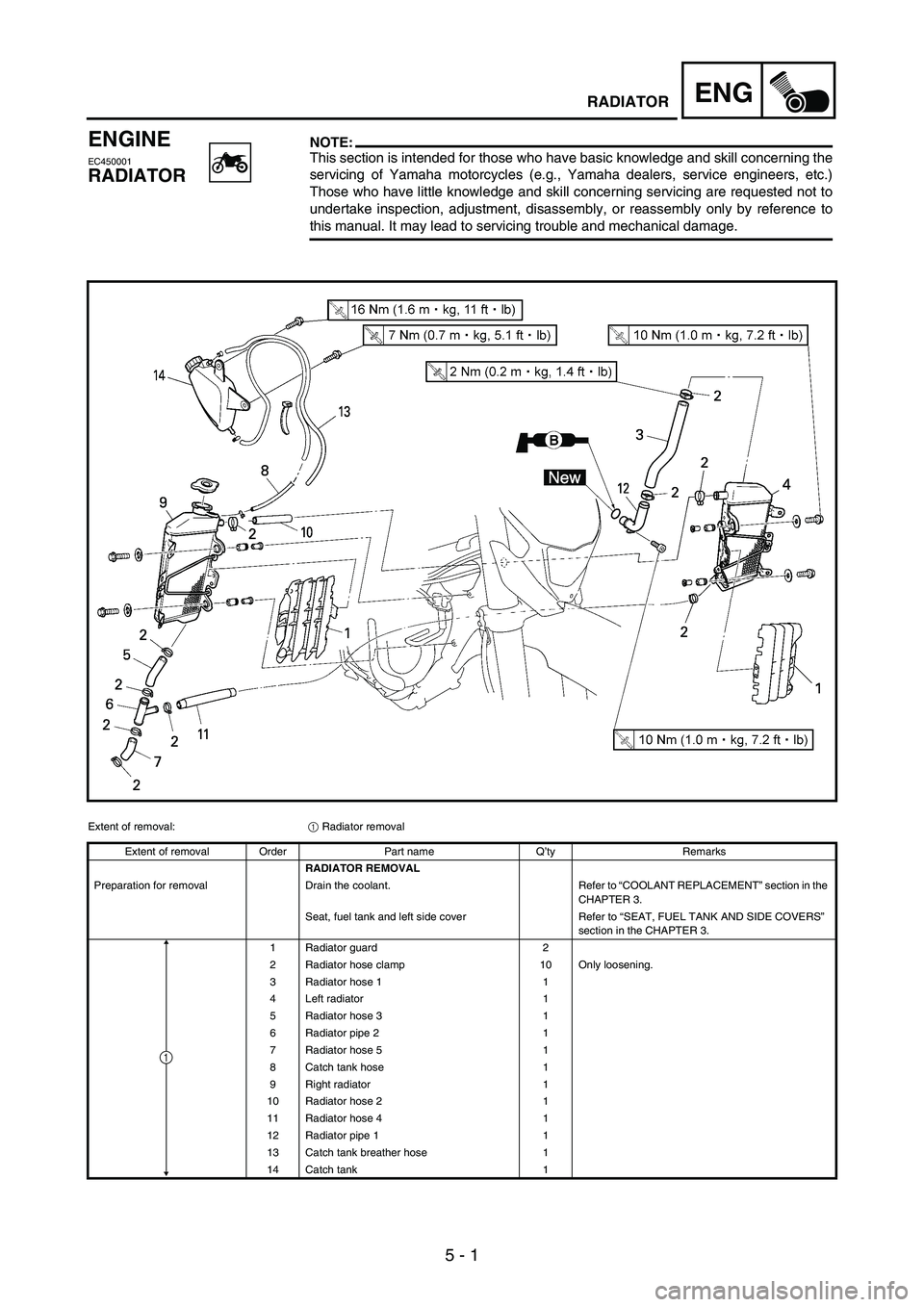
5 - 1
ENGRADIATOR
ENGINE
EC450001
RADIATOR
NOTE:This section is intended for those who have basic knowledge and skill concerning the
servicing of Yamaha motorcycles (e.g., Yamaha dealers, service engineers, etc.)
Those who have little knowledge and skill concerning servicing are requested not to
undertake inspection, adjustment, disassembly, or reassembly only by reference to
this manual. It may lead to servicing trouble and mechanical damage.
Extent of removal:
1 Radiator removal
Extent of removal Order Part name Q’ty Remarks
RADIATOR REMOVAL
Preparation for removal Drain the coolant. Refer to “COOLANT REPLACEMENT” section in the
CHAPTER 3.
Seat, fuel tank and left side cover Refer to “SEAT, FUEL TANK AND SIDE COVERS”
section in the CHAPTER 3.
1 Radiator guard 2
2 Radiator hose clamp 10 Only loosening.
3 Radiator hose 1 1
4 Left radiator 1
5 Radiator hose 3 1
6 Radiator pipe 2 1
7 Radiator hose 5 1
8 Catch tank hose 1
9 Right radiator 1
10 Radiator hose 2 1
11 Radiator hose 4 1
12 Radiator pipe 1 1
13 Catch tank breather hose 1
14 Catch tank 1
1