diagram YAMAHA WR 250F 2008 User Guide
[x] Cancel search | Manufacturer: YAMAHA, Model Year: 2008, Model line: WR 250F, Model: YAMAHA WR 250F 2008Pages: 224, PDF Size: 13.66 MB
Page 51 of 224

2-24
CABLE ROUTING DIAGRAM
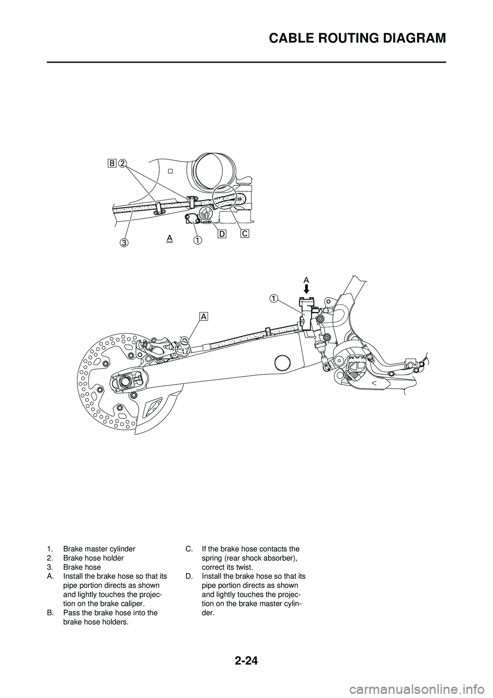
1. Brake master cylinder
2. Brake hose holder
3. Brake hose
A. Install the brake hose so that its
pipe portion directs as shown
and lightly touches the projec-
tion on the brake caliper.
B. Pass the brake hose into the
brake hose holders. C. If the brake hose contacts the
spring (rear shock absorber),
correct its twist.
D. Install the brake hose so that its pipe portion directs as shown
and lightly touches the projec-
tion on the brake master cylin-
der.
Page 52 of 224

2-25
CABLE ROUTING DIAGRAM
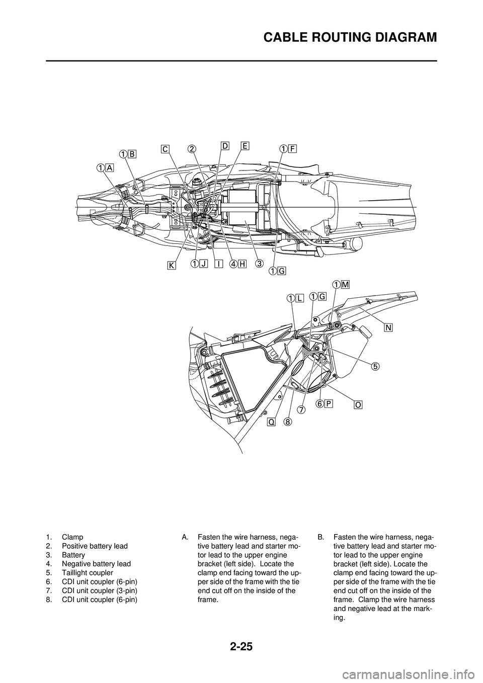
1. Clamp
2. Positive battery lead
3. Battery
4. Negative battery lead
5. Taillight coupler
6. CDI unit coupler (6-pin)
7. CDI unit coupler (3-pin)
8. CDI unit coupler (6-pin)A. Fasten the wire harness, nega-
tive battery lead and starter mo-
tor lead to the upper engine
bracket (left side). Locate the
clamp end facing toward the up-
per side of the frame with the tie
end cut off on the inside of the
frame. B. Fasten the wire harness, nega-
tive battery lead and starter mo-
tor lead to the upper engine
bracket (left side). Locate the
clamp end facing toward the up-
per side of the frame with the tie
end cut off on the inside of the
frame. Clamp the wire harness
and negative lead at the mark-
ing.
Page 53 of 224

2-26
CABLE ROUTING DIAGRAM
C. Pass the starter motor lead through the hole in the relay
holder.
D. Fit the cover securely.
E. Connect the wire harness to the starter relay.
F. Fasten the catch tank breather
hose and catch tank hose to the
rear frame. Clamp them close to
where they are joined to the
frame. Fasten the pipe tightly
enough not to crush it. Locate
the clamp end facing toward the
rear of the frame with the tie end
facing downward.
G. Fasten the (three) CDI unit leads
and taillight lead to the rear
frame. Locate the clamp end
facing toward the upper side of
the frame and cut off the tie end.
H. Connect the negative battery lead to the battery negative ter-
minal.
I. Connect the negative battery lead to the wire harness.
J. Fasten the wire harness to the rear frame. Locate the clamp
end facing toward the upper side
of the frame and the tie end to-
ward the inside of the frame.
Clamp the wire harness at the
marking.
K. Pass the wire harness, starter relay lead, starting circuit cut-off
relay lead and negative battery
lead through the hole in the relay
holder.
L. Fasten the (three) CDI unit leads and taillight lead to the rear
frame. Locate the clamp end
facing toward the lower side of
the frame and cut off the tie end.
M. Fasten the taillight lead to the rear frame. Locate the clamp
end facing toward the upper side
of the frame and cut off the tie
end.
N. Do not allow the taillight lead to
slacken.
O. Locate the CDI unit lead be- tween the CDI unit and rear
fender.
P. Locate the CDI unit coupler in the clearance between the up-
per side of the CDI unit and low-
er side of the catch tank stay.
Q. Locate the CDI unit lead be-
tween the CDI unit and rear
frame.
Page 54 of 224

2-27
CABLE ROUTING DIAGRAM
1. Throttle cable
2. Clamp
3. Brake hose
4. Clutch cable
5. Hose guide
6. Main switch coupler
7. Wire harness
8. Headlight coupler
9. Hot starter cable
10. Multi-function display bracket
11. Main switch12. Upper bracket
13. Clutch switch coupler
14. Engine stop switch coupler
15. Multi-function display coupler
16. Start switch coupler
17. Speed sensor coupler
18. Speed sensor lead
A. Fasten the star
t switch lead to
the handlebar with the plastic
bands. B. Fasten the engine stop switch
lead and clutch switch lead to
the handlebar with the plastic
bands.
C. Pass the brake hose through
the hose guides.
D. Secure the coupler by inserting it into the multi-function display
bracket.
Page 55 of 224

2-28
CABLE ROUTING DIAGRAM
E. Pass the throttle cables, clutch cable and hot starter cable be-
tween the upper bracket and
multi-function display bracket.
F. Fasten the multi-function display leads to the bracket. Cut off the
tie end.
G. Secure the coupler by pushing it into the hole in the multi-function
display bracket.
H. Secure the wire harness clip by pushing it into the hole in the
multi-function display bracket on
the inside.
I. Fasten the wire harness to the multi-function display bracket.
Cut off the tie end.
J. Fasten the main switch lead (wire harness side) to the multi-
function display br acket. Locate
the clamp end facing toward the
lower side of the frame and cut
off the tie end.
K. Pass the speed sensor lead through the guide on the outside
of the front fork.
Page 202 of 224

7-1
ELECTRICAL COMPONENTS AND WIRING DIAGRAM
ELECTRICAL
ELECTRICAL COMPONENTS AND WIRING DIAGRAM
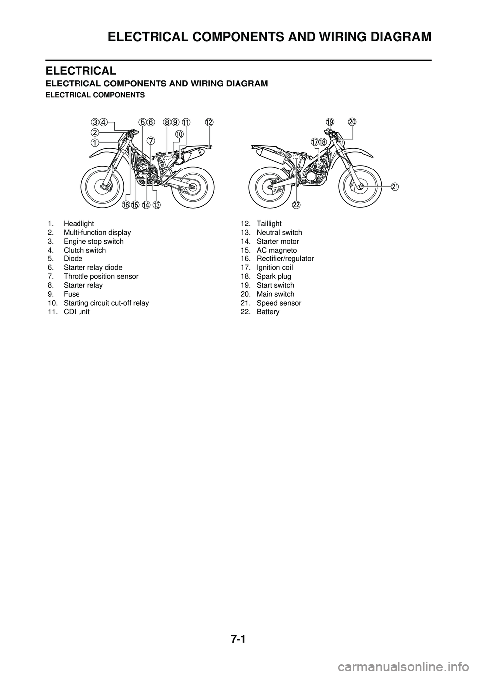
ELECTRICAL COMPONENTS1. Headlight
2. Multi-function display
3. Engine stop switch
4. Clutch switch
5. Diode
6. Starter relay diode
7. Throttle position sensor
8. Starter relay
9. Fuse
10. Starting circuit cut-off relay
11. CDI unit 12. Taillight
13. Neutral switch
14. Starter motor
15. AC magneto
16. Rectifier/regulator
17. Ignition coil
18. Spark plug
19. Start switch
20. Main switch
21. Speed sensor
22. Battery
Page 203 of 224

7-2
ELECTRICAL COMPONENTS AND WIRING DIAGRAM
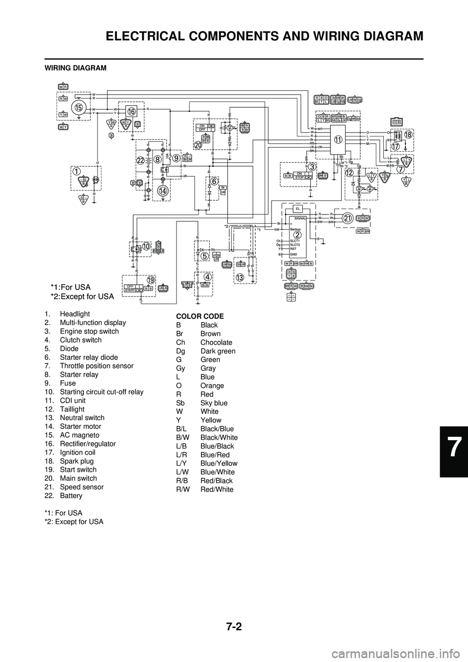
WIRING DIAGRAM
1. Headlight
2. Multi-function display
3. Engine stop switch
4. Clutch switch
5. Diode
6. Starter relay diode
7. Throttle position sensor
8. Starter relay
9. Fuse
10. Starting circuit cut-off relay
11. CDI unit
12. Taillight
13. Neutral switch
14. Starter motor
15. AC magneto
16. Rectifier/regulator
17. Ignition coil
18. Spark plug
19. Start switch
20. Main switch
21. Speed sensor
22. Battery
*1: For USA
*2: Except for USACOLOR CODE
BBlack
Br Brown
Ch Chocolate
Dg Dark green
GGreen
Gy Gray
LBlue
O Orange
RRed
Sb Sky blue
WWhite
YYellow
B/L Black/Blue
B/W Black/White
L/B Blue/Black
L/R Blue/Red
L/Y Blue/Yellow
L/W Blue/White
R/B Red/Black
R/W Red/White
7