sensor YAMAHA WR 250F 2008 User Guide
[x] Cancel search | Manufacturer: YAMAHA, Model Year: 2008, Model line: WR 250F, Model: YAMAHA WR 250F 2008Pages: 224, PDF Size: 13.66 MB
Page 162 of 224
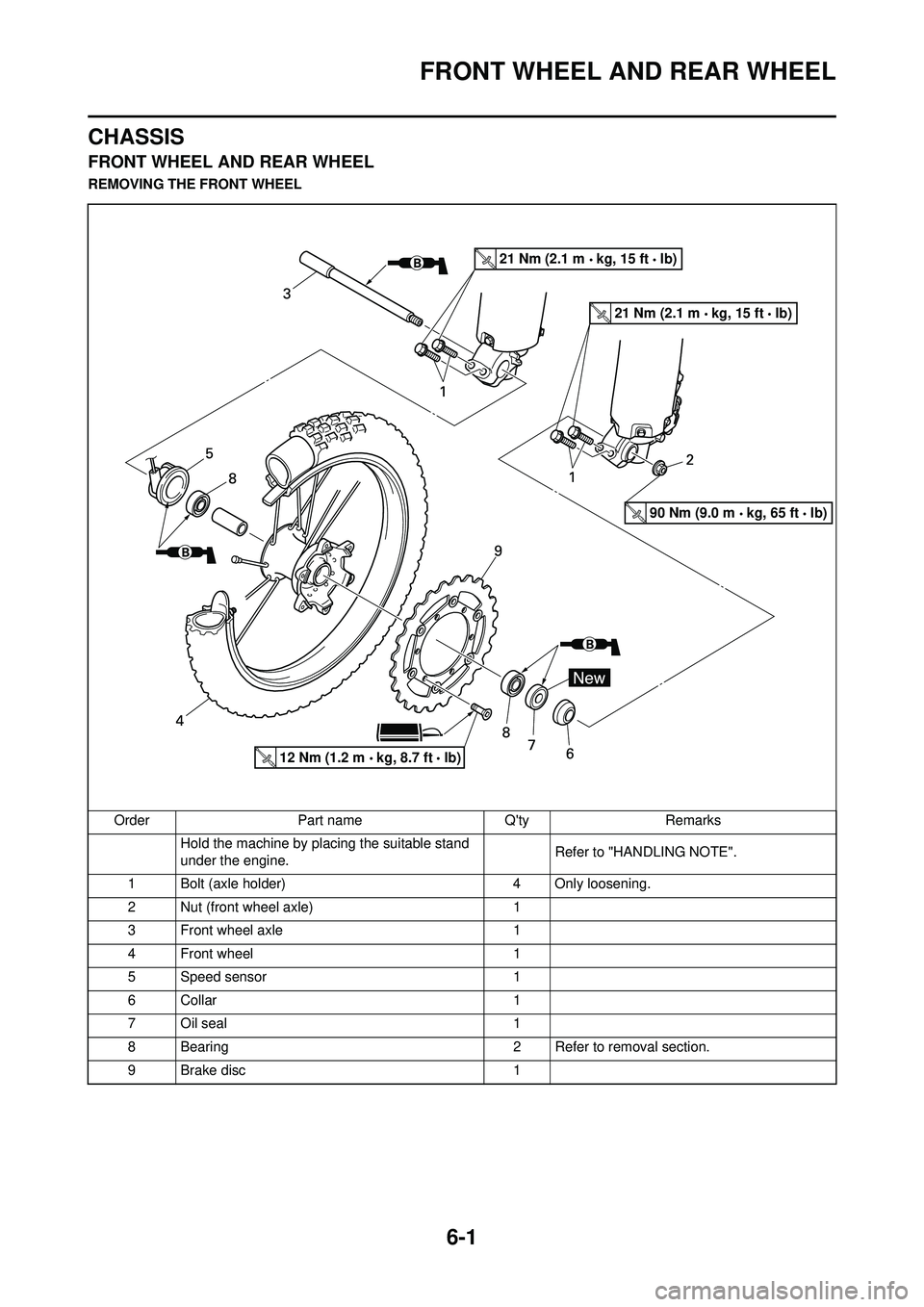
6-1
FRONT WHEEL AND REAR WHEEL
CHASSIS
FRONT WHEEL AND REAR WHEEL
REMOVING THE FRONT WHEELOrder Part name Q'ty Remarks Hold the machine by placing the suitable stand
under the engine. Refer to "HANDLING NOTE".
1 Bolt (axle holder) 4 Only loosening.
2 Nut (front wheel axle) 1
3 Front wheel axle 1
4 Front wheel 1
5 Speed sensor 1
6 Collar 1
7 Oil seal 1
8 Bearing 2 Refer to removal section.
9 Brake disc 1
21 Nm (2.1 m kg, 15 ft lb)
21 Nm (2.1 m kg, 15 ft lb)
12 Nm (1.2 m kg, 8.7 ft lb)
90 Nm (9.0 m kg, 65 ft lb)
Page 165 of 224
6-4
FRONT WHEEL AND REAR WHEEL
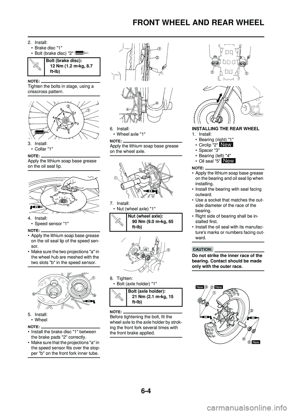
2. Install:• Brake disc "1"
• Bolt (brake disc) "2"
Tighten the bolts in stage, using a
crisscross pattern.
3. Install:•Collar "1"
Apply the lithium soap base grease
on the oil seal lip.
4. Install:• Speed sensor "1"
• Apply the lithium soap base grease on the oil seal lip of the speed sen-
sor.
• Make sure the two projections "a" in the wheel hub are meshed with the
two slots "b" in the speed sensor.
5. Install:• Wheel
• Install the brake disc "1" between
the brake pads "2" correctly.
• Make sure that the projections "a" in the speed sensor fits over the stop-
per "b" on the front fork inner tube.
6. Install:• Wheel axle "1"
Apply the lithium soap base grease
on the wheel axle.
7. Install:• Nut (wheel axle) "1"
8. Tighten: • Bolt (axle holder) "1"
Before tightening the bolt, fit the
wheel axle to the axle holder by strok-
ing the front fork several times with
the front brake applied.
INSTALLING THE REAR WHEEL
1. Install:• Bearing (right) "1"
• Circlip "2"
• Spacer "3"
• Bearing (left) "4"
• Oil seal "5"
• Apply the lithium soap base grease on the bearing and oil seal lip when
installing.
• Install the bearing with seal facing outward.
• Use a socket that matches the out-
side diameter of the race of the
bearing.
• Right side of bearing shall be in- stalled first.
• Install the oil seal with its manufac-
ture's marks or numbers facing out-
ward.
Do not strike the inner race of the
bearing. Contact should be made
only with the outer race.
Bolt (brake disc): 12 Nm (1.2 m•kg, 8.7
ft•lb)
Nut (wheel axle):
90 Nm (9.0 m•kg, 65
ft•lb)
Bolt (axle holder): 21 Nm (2.1 m•kg, 15
ft•lb)
Page 183 of 224
6-22
FRONT FORK
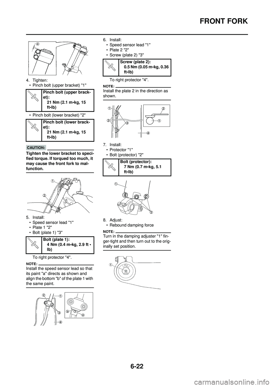
4. Tighten:• Pinch bolt (upper bracket) "1"
• Pinch bolt (lower bracket) "2"
Tighten the lower bracket to speci-
fied torque. If to rqued too much, it
may cause the fron t fork to mal-
function.
5. Install:
• Speed sensor lead "1"
• Plate 1 "2"
• Bolt (plate 1) "3"
To right protector "4".
Install the speed sensor lead so that
its paint "a" directs as shown and
align the bottom "b" of the plate 1 with
the same paint.
6. Install:• Speed sensor lead "1"
•Plate 2 "2"
• Screw (plate 2) "3"
To right protector "4".
Install the plate 2 in the direction as
shown.
7. Install:• Protector "1"
• Bolt (protector) "2"
8. Adjust: • Rebound damping force
Turn in the damping adjuster "1" fin-
ger-tight and then turn out to the orig-
inally set position.
Pinch bolt (upper brack-
et): 21 Nm (2.1 m•kg, 15
ft•lb)
Pinch bolt (lower brack-
et): 21 Nm (2.1 m•kg, 15
ft•lb)
Bolt (plate 1): 4 Nm (0.4 m•kg, 2.9 ft •
lb)
Screw (plate 2):0.5 Nm (0.05 m•kg, 0.36
ft•lb)
Bolt (protector): 7 Nm (0.7 m•kg, 5.1
ft•lb)
Page 191 of 224
6-30
STEERING
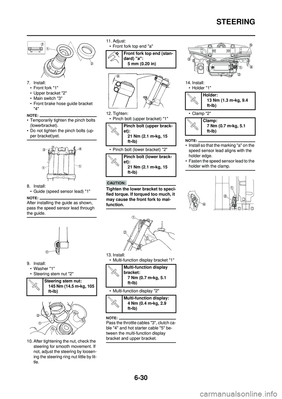
7. Install:• Front fork "1"
• Upper bracket "2"
• Main switch "3"
• Front brake hose guide bracket
"4"
• Temporarily tighten the pinch bolts (lowerbracket).
• Do not tighten the pinch bolts (up-
per bracket)yet.
8. Install:• Guide (speed sensor lead) "1"
After installing the guide as shown,
pass the speed sensor lead through
the guide.
9. Install:• Washer "1"
• Steering stem nut "2"
10. After tightening the nut, check the steering for smooth movement. If
not, adjust the steering by loosen-
ing the steering ring nut little by lit-
tle. 11. Adjust:
• Front fork top end "a"
12. Tighten: • Pinch bolt (upper bracket) "1"
• Pinch bolt (lower bracket) "2"
Tighten the lower bracket to speci-
fied torque. If to rqued too much, it
may cause the front fork to mal-
function.
13. Install: • Multi-function display bracket "1"
• Multi-function display "2"
Pass the throttle cables "3", clutch ca-
ble "4" and hot starter cable "5" be-
tween the multi-function display
bracket and upper bracket.
14. Install: • Holder "1"
• Clamp "2"
• Install so that the marking "a" on the speed sensor lead aligns with the
holder edge.
• Fasten the speed sensor lead to the holder with the clamp.
Steering stem nut:
145 Nm (14.5 m•kg, 105
ft•lb)
Front fork top end (stan-
dard) "a":5 mm (0.20 in)
Pinch bolt (upper brack-
et): 21 Nm (2.1 m•kg, 15
ft•lb)
Pinch bolt (lower brack-
et): 21 Nm (2.1 m•kg, 15
ft•lb)
Multi-function display
bracket: 7 Nm (0.7 m•kg, 5.1
ft•lb)
Multi-function display: 4 Nm (0.4 m•kg, 2.9
ft•lb)
Holder: 13 Nm (1.3 m•kg, 9.4
ft•lb)
Clamp: 7 Nm (0.7 m•kg, 5.1
ft•lb)
Page 202 of 224
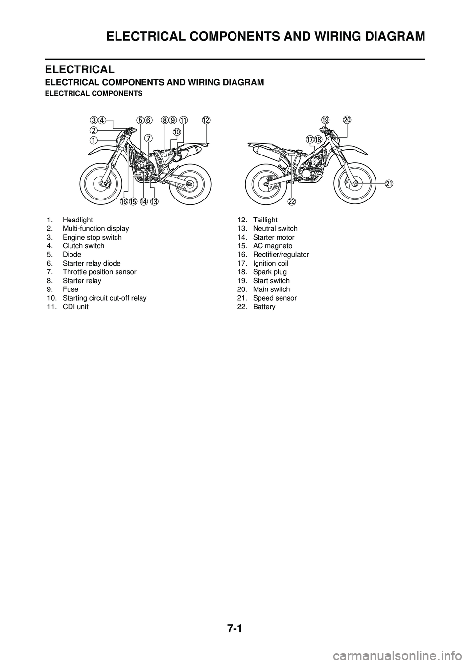
7-1
ELECTRICAL COMPONENTS AND WIRING DIAGRAM
ELECTRICAL
ELECTRICAL COMPONENTS AND WIRING DIAGRAM
ELECTRICAL COMPONENTS1. Headlight
2. Multi-function display
3. Engine stop switch
4. Clutch switch
5. Diode
6. Starter relay diode
7. Throttle position sensor
8. Starter relay
9. Fuse
10. Starting circuit cut-off relay
11. CDI unit 12. Taillight
13. Neutral switch
14. Starter motor
15. AC magneto
16. Rectifier/regulator
17. Ignition coil
18. Spark plug
19. Start switch
20. Main switch
21. Speed sensor
22. Battery
Page 203 of 224
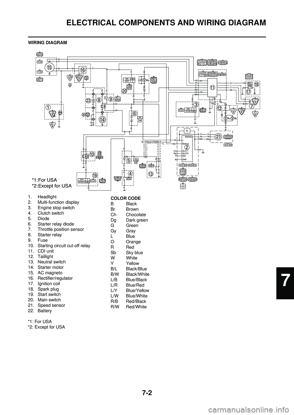
7-2
ELECTRICAL COMPONENTS AND WIRING DIAGRAM
WIRING DIAGRAM
1. Headlight
2. Multi-function display
3. Engine stop switch
4. Clutch switch
5. Diode
6. Starter relay diode
7. Throttle position sensor
8. Starter relay
9. Fuse
10. Starting circuit cut-off relay
11. CDI unit
12. Taillight
13. Neutral switch
14. Starter motor
15. AC magneto
16. Rectifier/regulator
17. Ignition coil
18. Spark plug
19. Start switch
20. Main switch
21. Speed sensor
22. Battery
*1: For USA
*2: Except for USACOLOR CODE
BBlack
Br Brown
Ch Chocolate
Dg Dark green
GGreen
Gy Gray
LBlue
O Orange
RRed
Sb Sky blue
WWhite
YYellow
B/L Black/Blue
B/W Black/White
L/B Blue/Black
L/R Blue/Red
L/Y Blue/Yellow
L/W Blue/White
R/B Red/Black
R/W Red/White
7
Page 216 of 224
7-15
THROTTLE POSITION SENSOR SYSTEM
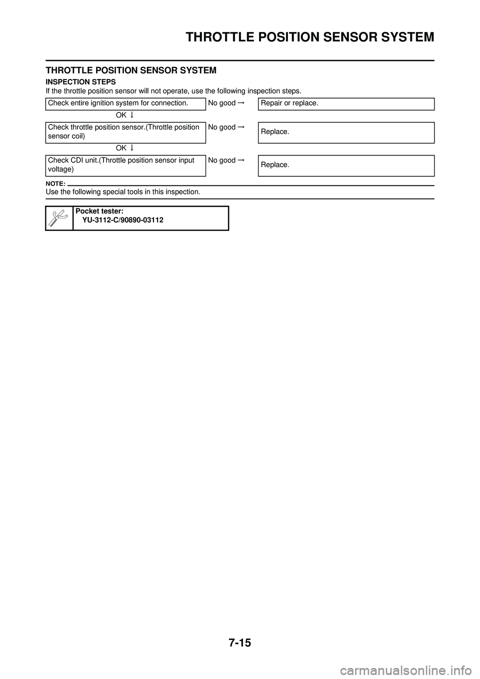
THROTTLE POSITION SENSOR SYSTEM
INSPECTION STEPS
If the throttle position sensor will not operate, use the following inspection steps.
Use the following special tools in this inspection.
Check entire ignition system for connection. No good →Repair or replace.
OK ↓
Check throttle position sensor.(Throttle position
sensor coil) No good
→
Replace.
OK ↓
Check CDI unit.(Throttle position sensor input
voltage) No good
→
Replace.
Pocket tester:
YU-3112-C/90890-03112
Page 217 of 224
7-16
THROTTLE POSITION SENSOR SYSTEM
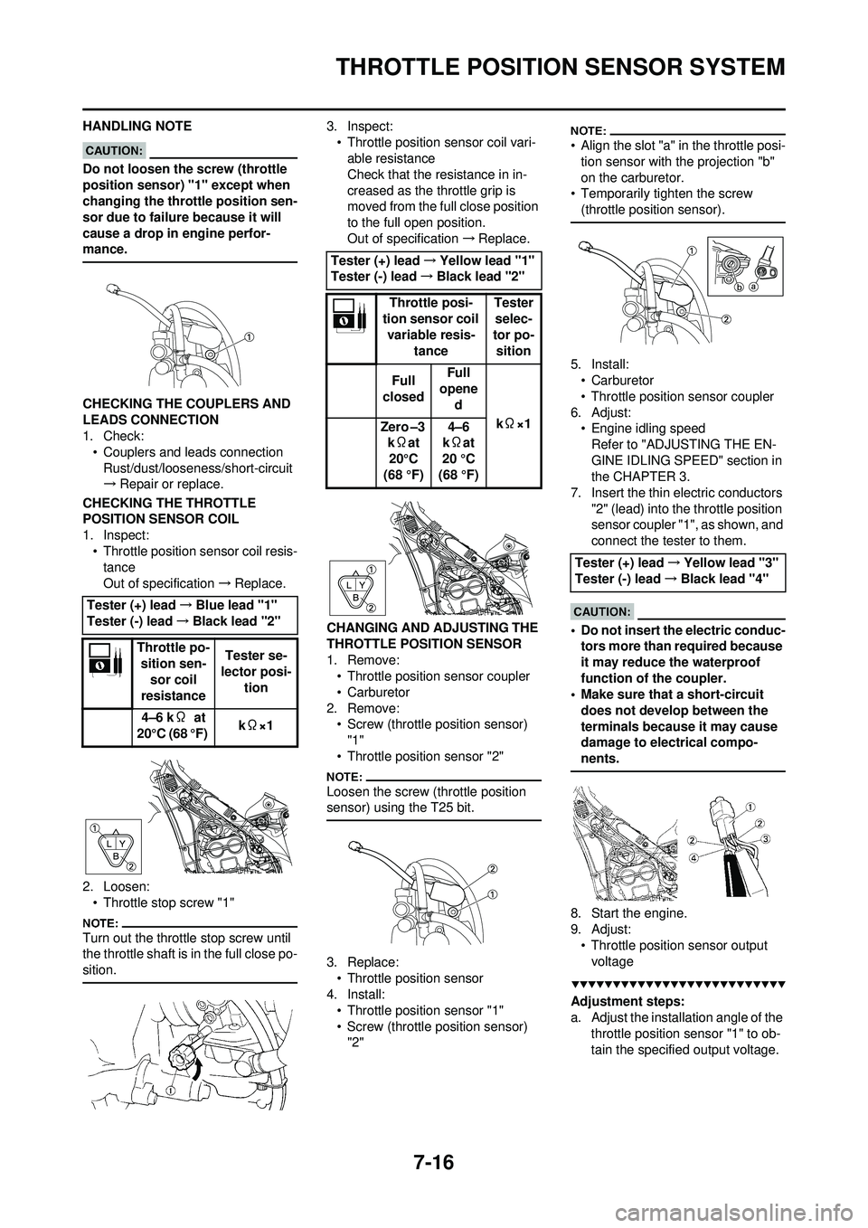
HANDLING NOTE
Do not loosen the screw (throttle
position sensor) "1" except when
changing the throttle position sen-
sor due to failure because it will
cause a drop in engine perfor-
mance.
CHECKING THE COUPLERS AND
LEADS CONNECTION
1. Check: • Couplers and leads connectionRust/dust/looseness/short-circuit
→ Repair or replace.
CHECKING THE THROTTLE
POSITION SENSOR COIL
1. Inspect: • Throttle position sensor coil resis-tance
Out of specification →Replace.
2. Loosen: • Throttle stop screw "1"
Turn out the throttle stop screw until
the throttle shaft is in the full close po-
sition.
3. Inspect:• Throttle position sensor coil vari-able resistance
Check that the resistance in in-
creased as the throttle grip is
moved from the full close position
to the full open position.
Out of specification →Replace.
CHANGING AND ADJUSTING THE
THROTTLE POSI TION SENSOR
1. Remove: • Throttle position sensor coupler
• Carburetor
2. Remove: • Screw (throttle position sensor) "1"
• Throttle position sensor "2"
Loosen the screw (throttle position
sensor) using the T25 bit.
3. Replace: • Throttle position sensor
4. Install: • Throttle position sensor "1"
• Screw (throttle position sensor) "2"
• Align the slot "a" in the throttle posi-tion sensor with the projection "b"
on the carburetor.
• Temporarily tighten the screw (throttle position sensor).
5. Install:•Carburetor
• Throttle position sensor coupler
6. Adjust: • Engine idling speedRefer to "ADJUSTING THE EN-
GINE IDLING SPEED" section in
the CHAPTER 3.
7. Insert the thin electric conductors
"2" (lead) into the throttle position
sensor coupler "1", as shown, and
connect the tester to them.
• Do not insert the electric conduc-tors more than required because
it may reduce the waterproof
function of the coupler.
• Make sure that a short-circuit
does not develop between the
terminals because it may cause
damage to electrical compo-
nents.
8. Start the engine.
9. Adjust:• Throttle position sensor output voltage
Adjustment steps:
a. Adjust the installation angle of the throttle position sensor "1" to ob-
tain the specified output voltage.
Tester (+) lead
→Blue lead "1"
Tester (-) lead →Black lead "2"
Throttle po- sition sen-
sor coil
resistance Tester se-
lector posi- tion
4–6 k Ω at
20°C (68 °F) k
Ω×1
Tester (+) lead →Yellow lead "1"
Tester (-) lead →Black lead "2"
Throttle posi-
tion sensor coil
variable resis- tance Tester
selec-
tor po- sition
Full
closed Full
opene
d
kΩ×1
Zero –3
k Ωat
20°C
(68 °F) 4–6
k Ωat
20 °C
(68 °F)
Tester (+) lead →Yellow lead "3"
Tester (-) lead →Black lead "4"
Page 218 of 224
7-17
THROTTLE POSITION SENSOR SYSTEM
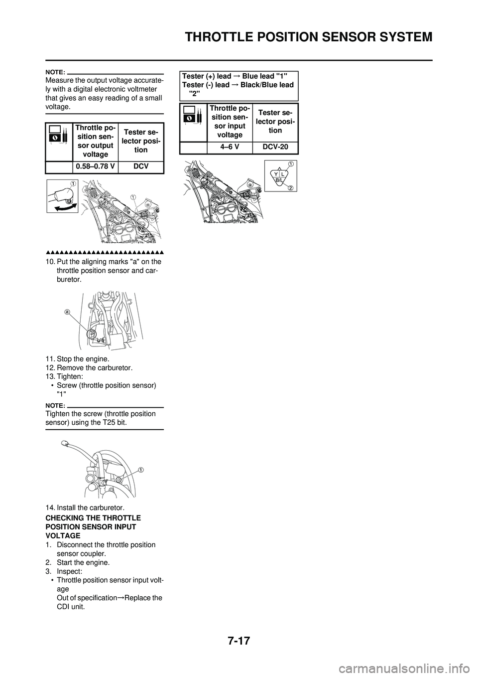
Measure the output voltage accurate-
ly with a digital electronic voltmeter
that gives an easy reading of a small
voltage.
10. Put the aligning marks "a" on the throttle position sensor and car-
buretor.
11. Stop the engine.
12. Remove the carburetor.
13. Tighten: • Screw (throttle position sensor) "1"
Tighten the screw (throttle position
sensor) using the T25 bit.
14. Install the carburetor.
CHECKING THE THROTTLE
POSITION SENSOR INPUT
VOLTAGE
1. Disconnect the throttle position sensor coupler.
2. Start the engine.
3. Inspect: • Throttle position sensor input volt-age
Out of specification →Replace the
CDI unit. Throttle po-
sition sen-
sor output voltage Tester se-
lector posi- tion
0.58–0.78 V DCV
Tester (+) lead →Blue lead "1"
Tester (-) lead →Black/Blue lead
"2"
Throttle po-sition sen- sor input voltage Tester se-
lector posi-
tion
4–6 V DCV-20
Page 221 of 224
7-20
SIGNALING SYSTEM
SIGNALING SYSTEM
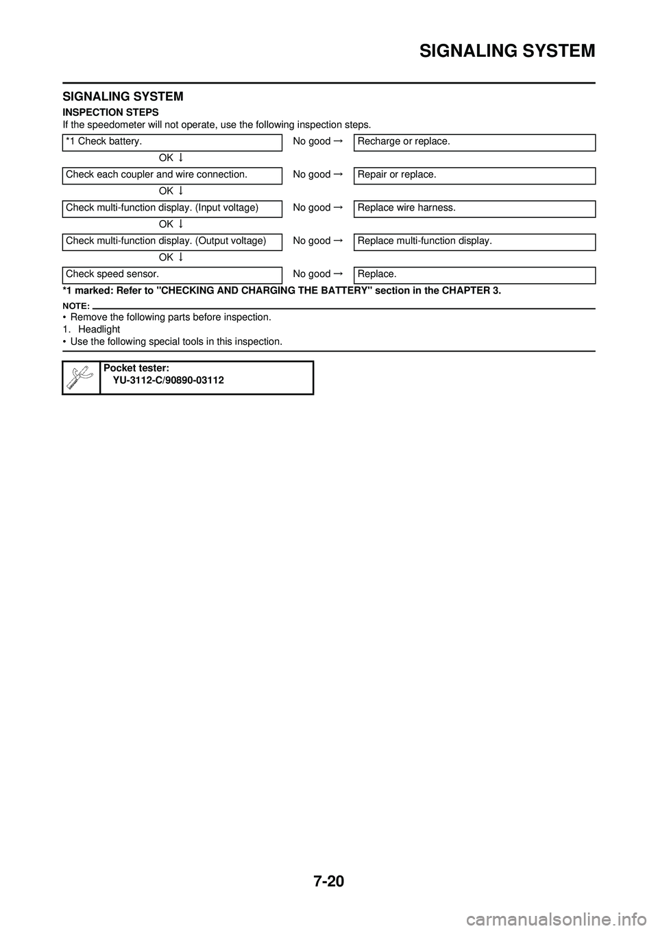
INSPECTION STEPS
If the speedometer will not operate, use the following inspection steps.
*1 marked: Refer to "CHECKING AND CHARGIN G THE BATTERY" section in the CHAPTER 3.
• Remove the following parts before inspection.
1. Headlight
• Use the following special tools in this inspection.
*1 Check battery. No good→Recharge or replace.
OK ↓
Check each coupler and wire connection. No good →Repair or replace.
OK ↓
Check multi-function display. (Input voltage) No good →Replace wire harness.
OK ↓
Check multi-function displa y. (Output voltage) No good →Replace multi-function display.
OK ↓
Check speed sensor. No good→Replace.
Pocket tester:
YU-3112-C/90890-03112