YAMAHA WR 250F 2008 Owners Manual
Manufacturer: YAMAHA, Model Year: 2008, Model line: WR 250F, Model: YAMAHA WR 250F 2008Pages: 224, PDF Size: 13.66 MB
Page 211 of 224
7-10
ELECTRIC STARTING SYSTEM
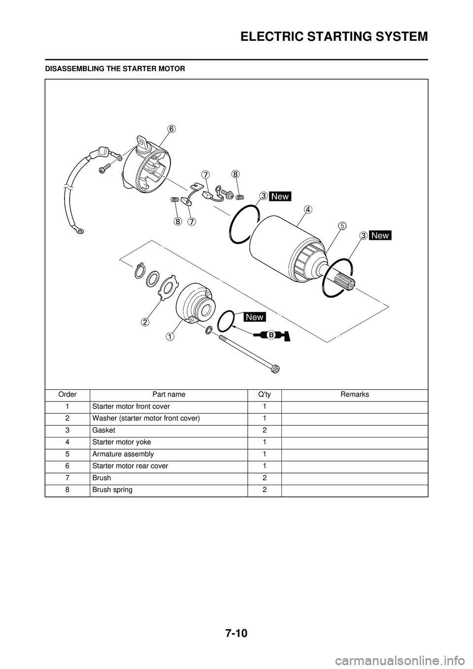
DISASSEMBLING THE STARTER MOTOROrder Part name Q'ty Remarks1 Starter motor front cover 1
2 Washer (starter motor front cover) 1
3 Gasket 2
4 Starter motor yoke 1
5 Armature assembly 1
6 Starter motor rear cover 1
7 Brush 2
8 Brush spring 2
Page 212 of 224
7-11
ELECTRIC STARTING SYSTEM
CHECKING AND REPAIRING THE
STARTER MOTOR
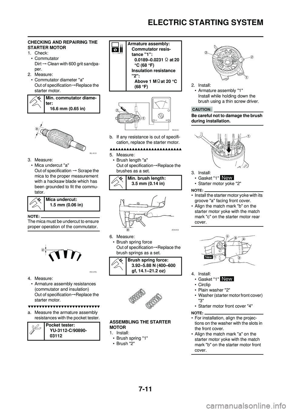
1. Check:• Commutator
Dirt →Clean with 600 grit sandpa-
per.
2. Measure:
• Commutator diameter "a"Out of specification →Replace the
starter motor.
3. Measure: • Mica undercut "a"
Out of specification →Scrape the
mica to the proper measurement
with a hacksaw bl ade which has
been grounded to fit the commu-
tator.
The mica must be undercut to ensure
proper operation of the commutator.
4. Measure: • Armature assembly resistances (commutator and insulation)
Out of specification →Replace the
starter motor.
a. Measure the armature assembly resistances with the pocket tester. b. If any resistance
is out of specifi-
cation, replace the starter motor.
5. Measure: • Brush length "a"
Out of specification →Replace the
brushes as a set.
6. Measure: • Brush spring forceOut of specification →Replace the
brush springs as a set.
ASSEMBLING THE STARTER
MOTOR
1. Install: • Brush spring "1"
•Brush "2" 2. Install:
• Armature assembly "1"
Install while holding down the
brush using a thin screw driver.
Be careful not to damage the brush
during installation.
3. Install:• Gasket "1"
• Starter motor yoke "2"
• Install the starter motor yoke with its groove "a" facing front cover.
• Align the match mark "b" on the
starter motor yoke with the match
mark "c" on the starter motor rear
cover.
4. Install:• Gasket "1"
• Circlip
• Plain washer "2"
• Washer (starter motor front cover)
"3"
• Starter motor front cover "4"
• For installation, align the projec- tions on the washer with the slots in
the front cover.
• Align the match mark "a" on the starter motor yoke with the match
mark "b" on the starter motor front
cover.
Min. commutator diame-
ter: 16.6 mm (0.65 in)
Mica undercut: 1.5 mm (0.06 in)
Pocket tester: YU-3112-C/90890-
03112
Armature assembly:
Commutator resis-
tance "1":0.0189–0.0231 Ω at 20
°C (68 °F)
Insulation resistance
"2":
Above 1 M Ωat 20 °C
(68 °F)
Min. brush length: 3.5 mm (0.14 in)
Brush spring force: 3.92–5.88 N (400–600
gf, 14.1–21.2 oz)
Page 213 of 224
7-12
ELECTRIC STARTING SYSTEM
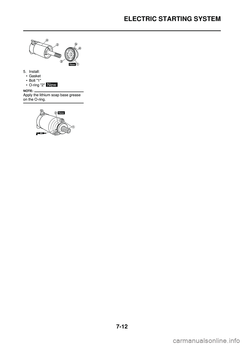
5. Install:• Gasket
•Bolt "1"
• O-ring "2"
Apply the lithium soap base grease
on the O-ring.
Page 214 of 224
7-13
CHARGING SYSTEM
CHARGING SYSTEM
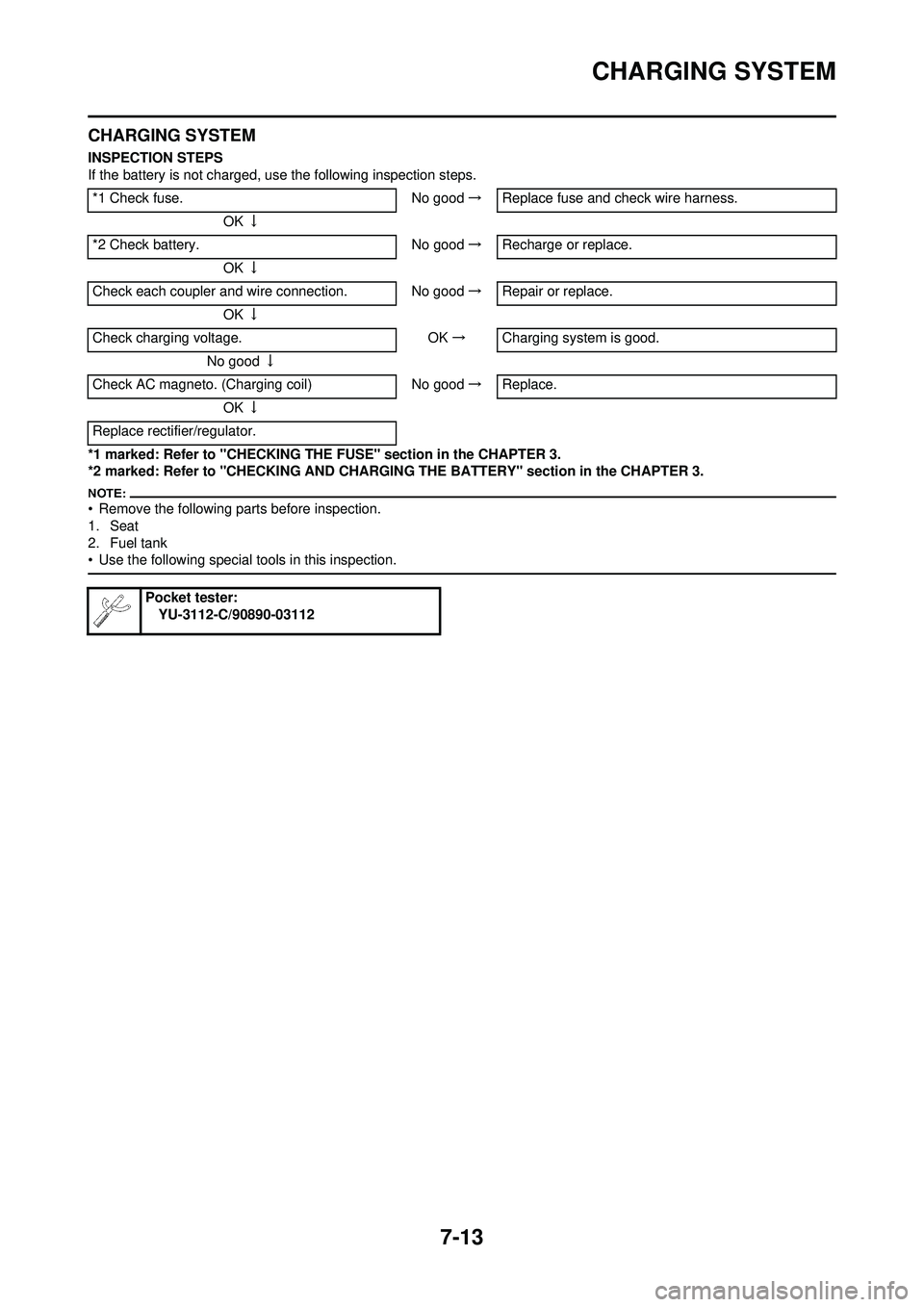
INSPECTION STEPS
If the battery is not charged, use the following inspection steps.
*1 marked: Refer to "CHECKING TH E FUSE" section in the CHAPTER 3.
*2 marked: Refer to "CHECKING AND CHARGIN G THE BATTERY" section in the CHAPTER 3.
• Remove the following parts before inspection.
1. Seat
2. Fuel tank
• Use the following special tools in this inspection.
*1 Check fuse. No good→Replace fuse and check wire harness.
OK ↓
*2 Check battery. No good→Recharge or replace.
OK ↓
Check each coupler and wire connection. No good →Repair or replace.
OK ↓
Check charging voltage. OK→ Charging system is good.
No good ↓
Check AC magneto. (Charging coil) No good→Replace.
OK ↓
Replace rectifier/regulator.
Pocket tester: YU-3112-C/90890-03112
Page 215 of 224
7-14
CHARGING SYSTEM
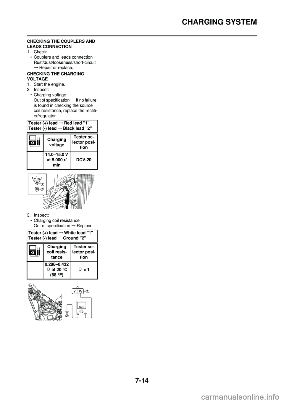
CHECKING THE COUPLERS AND
LEADS CONNECTION
1. Check:• Couplers and leads connection
Rust/dust/looseness/short-circuit
→ Repair or replace.
CHECKING THE CHARGING
VOLTAGE
1. Start the engine.
2. Inspect: • Charging voltageOut of specification →If no failure
is found in checking the source
coil resistance, replace the rectifi-
er/regulator.
3. Inspect: • Charging coil resistanceOut of specification →Replace.
Tester (+) lead
→Red lead "1"
Tester (-) lead →Black lead "2"
Charging voltage Tester se-
lector posi- tion
14.0–15.0 V at 5,000 r/ min DCV-20
Tester (+) lead →White lead "1"
Tester (-) lead →Ground "2"
Charging
coil resis- tance Tester se-
lector posi- tion
0.288–0.432 Ω at 20 °C
(68 °F) Ω × 1
Page 216 of 224
7-15
THROTTLE POSITION SENSOR SYSTEM
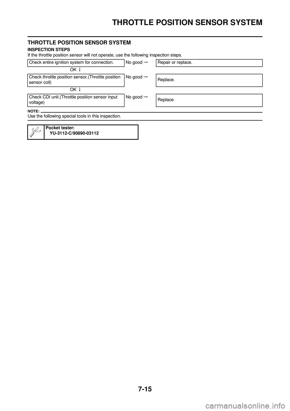
THROTTLE POSITION SENSOR SYSTEM
INSPECTION STEPS
If the throttle position sensor will not operate, use the following inspection steps.
Use the following special tools in this inspection.
Check entire ignition system for connection. No good →Repair or replace.
OK ↓
Check throttle position sensor.(Throttle position
sensor coil) No good
→
Replace.
OK ↓
Check CDI unit.(Throttle position sensor input
voltage) No good
→
Replace.
Pocket tester:
YU-3112-C/90890-03112
Page 217 of 224
7-16
THROTTLE POSITION SENSOR SYSTEM
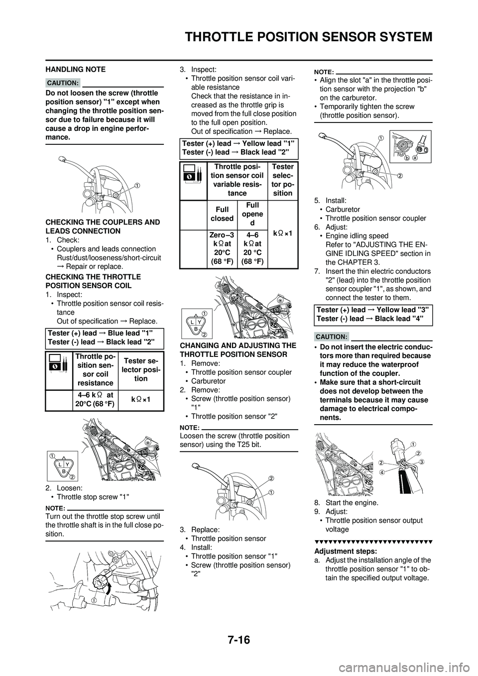
HANDLING NOTE
Do not loosen the screw (throttle
position sensor) "1" except when
changing the throttle position sen-
sor due to failure because it will
cause a drop in engine perfor-
mance.
CHECKING THE COUPLERS AND
LEADS CONNECTION
1. Check: • Couplers and leads connectionRust/dust/looseness/short-circuit
→ Repair or replace.
CHECKING THE THROTTLE
POSITION SENSOR COIL
1. Inspect: • Throttle position sensor coil resis-tance
Out of specification →Replace.
2. Loosen: • Throttle stop screw "1"
Turn out the throttle stop screw until
the throttle shaft is in the full close po-
sition.
3. Inspect:• Throttle position sensor coil vari-able resistance
Check that the resistance in in-
creased as the throttle grip is
moved from the full close position
to the full open position.
Out of specification →Replace.
CHANGING AND ADJUSTING THE
THROTTLE POSI TION SENSOR
1. Remove: • Throttle position sensor coupler
• Carburetor
2. Remove: • Screw (throttle position sensor) "1"
• Throttle position sensor "2"
Loosen the screw (throttle position
sensor) using the T25 bit.
3. Replace: • Throttle position sensor
4. Install: • Throttle position sensor "1"
• Screw (throttle position sensor) "2"
• Align the slot "a" in the throttle posi-tion sensor with the projection "b"
on the carburetor.
• Temporarily tighten the screw (throttle position sensor).
5. Install:•Carburetor
• Throttle position sensor coupler
6. Adjust: • Engine idling speedRefer to "ADJUSTING THE EN-
GINE IDLING SPEED" section in
the CHAPTER 3.
7. Insert the thin electric conductors
"2" (lead) into the throttle position
sensor coupler "1", as shown, and
connect the tester to them.
• Do not insert the electric conduc-tors more than required because
it may reduce the waterproof
function of the coupler.
• Make sure that a short-circuit
does not develop between the
terminals because it may cause
damage to electrical compo-
nents.
8. Start the engine.
9. Adjust:• Throttle position sensor output voltage
Adjustment steps:
a. Adjust the installation angle of the throttle position sensor "1" to ob-
tain the specified output voltage.
Tester (+) lead
→Blue lead "1"
Tester (-) lead →Black lead "2"
Throttle po- sition sen-
sor coil
resistance Tester se-
lector posi- tion
4–6 k Ω at
20°C (68 °F) k
Ω×1
Tester (+) lead →Yellow lead "1"
Tester (-) lead →Black lead "2"
Throttle posi-
tion sensor coil
variable resis- tance Tester
selec-
tor po- sition
Full
closed Full
opene
d
kΩ×1
Zero –3
k Ωat
20°C
(68 °F) 4–6
k Ωat
20 °C
(68 °F)
Tester (+) lead →Yellow lead "3"
Tester (-) lead →Black lead "4"
Page 218 of 224
7-17
THROTTLE POSITION SENSOR SYSTEM
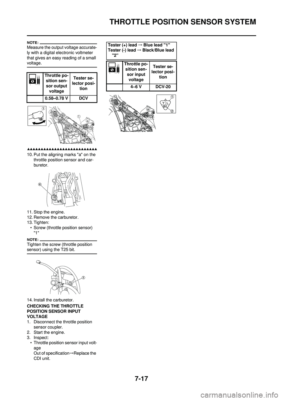
Measure the output voltage accurate-
ly with a digital electronic voltmeter
that gives an easy reading of a small
voltage.
10. Put the aligning marks "a" on the throttle position sensor and car-
buretor.
11. Stop the engine.
12. Remove the carburetor.
13. Tighten: • Screw (throttle position sensor) "1"
Tighten the screw (throttle position
sensor) using the T25 bit.
14. Install the carburetor.
CHECKING THE THROTTLE
POSITION SENSOR INPUT
VOLTAGE
1. Disconnect the throttle position sensor coupler.
2. Start the engine.
3. Inspect: • Throttle position sensor input volt-age
Out of specification →Replace the
CDI unit. Throttle po-
sition sen-
sor output voltage Tester se-
lector posi- tion
0.58–0.78 V DCV
Tester (+) lead →Blue lead "1"
Tester (-) lead →Black/Blue lead
"2"
Throttle po-sition sen- sor input voltage Tester se-
lector posi-
tion
4–6 V DCV-20
Page 219 of 224
7-18
LIGHTING SYSTEM
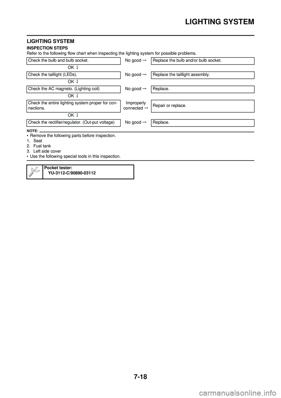
LIGHTING SYSTEM
INSPECTION STEPS
Refer to the following flow chart when inspecting the lighting system for possible problems.
• Remove the following parts before inspection.
1. Seat
2. Fuel tank
3. Left side cover
• Use the following special tools in this inspection.
Check the bulb and bulb socket.No good→Replace the bulb and/or bulb socket.
OK ↓
Check the taillight (LEDs). No good→Replace the taillight assembly.
OK ↓
Check the AC magneto. (Lighting coil) No good→Replace.
OK ↓
Check the entire lighting system proper for con-
nections. Improperly
connected →Repair or replace.
OK ↓
Check the rectifier/regulator. (Out-put voltage) No good →Replace.
Pocket tester:
YU-3112-C/90890-03112
Page 220 of 224
7-19
LIGHTING SYSTEM
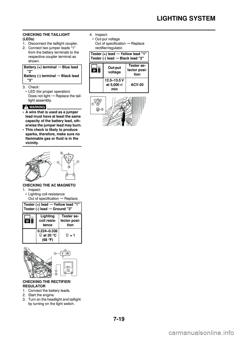
CHECKING THE TAILLIGHT
(LEDs)
1. Disconnect the taillight coupler.
2. Connect two jumper leads "1" from the battery terminals to the
respective coupler terminal as
shown.
3. Check: • LED (for proper operation)Does not light →Replace the tail-
light assembly.
• A wire that is used as a jumper lead must have at least the same
capacity of the battery lead, oth-
erwise the jumper lead may burn.
• This check is likely to produce sparks, therefore, make sure no
flammable gas or fluid is in the
vicinity.
CHECKING THE AC MAGNETO
1. Inspect:• Lighting coil resistance
Out of specification →Replace.
CHECKING THE RECTIFIER/
REGULATOR
1. Connect the battery leads.
2. Start the engine.
3. Turn on the headlight and taillight by turning on the light switch. 4. Inspect:
• Out-put voltageOut of specification →Replace
rectifier/regulator.
Battery (+) terminal →Blue lead
"2"
Battery (-) terminal →Black lead
"3"
Tester (+) lead →Yellow lead "1"
Tester (-) lead →Ground "2"
Lighting
coil resis-
tance Tester se-
lector posi-
tion
0.224–0.336 Ω at 20 °C (68 °F) Ω × 1
Tester (+) lead
→Yellow lead "1"
Tester (-) lead →Black lead "2"
Out-put voltage Tester se-
lector posi- tion
12.5–13.5 V at 5,000 r/ min ACV-20