recommended oil YAMAHA WR 250F 2011 Owners Manual
[x] Cancel search | Manufacturer: YAMAHA, Model Year: 2011, Model line: WR 250F, Model: YAMAHA WR 250F 2011Pages: 232, PDF Size: 14.29 MB
Page 6 of 232
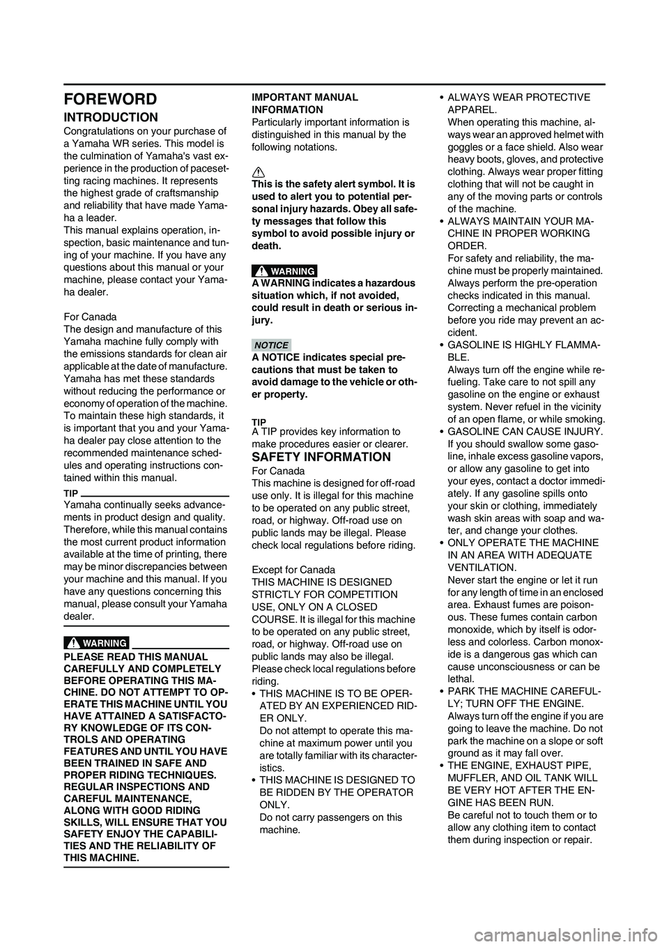
FOREWORD
INTRODUCTION
Congratulations on your purchase of
a Yamaha WR series. This model is
the culmination of Yamaha's vast ex-
perience in the production of paceset-
ting racing machines. It represents
the highest grade of craftsmanship
and reliability that have made Yama-
ha a leader.
This manual explains operation, in-
spection, basic maintenance and tun-
ing of your machine. If you have any
questions about this manual or your
machine, please contact your Yama-
ha dealer.
For Canada
The design and manufacture of this
Yamaha machine fully comply with
the emissions standards for clean air
applicable at the date of manufacture.
Yamaha has met these standards
without reducing the performance or
economy of operation of the machine.
To maintain these high standards, it
is important that you and your Yama-
ha dealer pay close attention to the
recommended maintenance sched-
ules and operating instructions con-
tained within this manual.
Yamaha continually seeks advance-
ments in product design and quality.
Therefore, while this manual contains
the most current product information
available at the time of printing, there
may be minor discrepancies between
your machine and this manual. If you
have any questions concerning this
manual, please consult your Yamaha
dealer.
PLEASE READ THIS MANUAL
CAREFULLY AND COMPLETELY
BEFORE OPERATING THIS MA-
CHINE. DO NOT ATTEMPT TO OP-
ERATE THIS MACHINE UNTIL YOU
HAVE ATTAINED A SATISFACTO-
RY KNOWLEDGE OF ITS CON-
TROLS AND OPERATING
FEATURES AND UNTIL YOU HAVE
BEEN TRAINED IN SAFE AND
PROPER RIDING TECHNIQUES.
REGULAR INSPECTIONS AND
CAREFUL MAINTENANCE,
ALONG WITH GOOD RIDING
SKILLS, WILL ENSURE THAT YOU
SAFETY ENJOY THE CAPABILI-
TIES AND THE RELIABILITY OF
THIS MACHINE.
IMPORTANT MANUAL
INFORMATION
Particularly important information is
distinguished in this manual by the
following notations.
This is the safety alert symbol. It is
used to alert you to potential per-
sonal injury hazards. Obey all safe-
ty messages that follow this
symbol to avoid possible injury or
death.
A WARNING indicates a hazardous
situation which, if not avoided,
could result in death or serious in-
jury.
A NOTICE indicates special pre-
cautions that must be taken to
avoid damage to the vehicle or oth-
er property.
A TIP provides key information to
make procedures easier or clearer.
SAFETY INFORMATION
For Canada
This machine is designed for off-road
use only. It is illegal for this machine
to be operated on any public street,
road, or highway. Off-road use on
public lands may be illegal. Please
check local regulations before riding.
Except for Canada
THIS MACHINE IS DESIGNED
STRICTLY FOR COMPETITION
USE, ONLY ON A CLOSED
COURSE. It is illegal for this machine
to be operated on any public street,
road, or highway. Off-road use on
public lands may also be illegal.
Please check local regulations before
riding.
• THIS MACHINE IS TO BE OPER-
ATED BY AN EXPERIENCED RID-
ER ONLY.
Do not attempt to operate this ma-
chine at maximum power until you
are totally familiar with its character-
istics.
• THIS MACHINE IS DESIGNED TO
BE RIDDEN BY THE OPERATOR
ONLY.
Do not carry passengers on this
machine.• ALWAYS WEAR PROTECTIVE
APPAREL.
When operating this machine, al-
ways wear an approved helmet with
goggles or a face shield. Also wear
heavy boots, gloves, and protective
clothing. Always wear proper fitting
clothing that will not be caught in
any of the moving parts or controls
of the machine.
• ALWAYS MAINTAIN YOUR MA-
CHINE IN PROPER WORKING
ORDER.
For safety and reliability, the ma-
chine must be properly maintained.
Always perform the pre-operation
checks indicated in this manual.
Correcting a mechanical problem
before you ride may prevent an ac-
cident.
• GASOLINE IS HIGHLY FLAMMA-
BLE.
Always turn off the engine while re-
fueling. Take care to not spill any
gasoline on the engine or exhaust
system. Never refuel in the vicinity
of an open flame, or while smoking.
• GASOLINE CAN CAUSE INJURY.
If you should swallow some gaso-
line, inhale excess gasoline vapors,
or allow any gasoline to get into
your eyes, contact a doctor immedi-
ately. If any gasoline spills onto
your skin or clothing, immediately
wash skin areas with soap and wa-
ter, and change your clothes.
• ONLY OPERATE THE MACHINE
IN AN AREA WITH ADEQUATE
VENTILATION.
Never start the engine or let it run
for any length of time in an enclosed
area. Exhaust fumes are poison-
ous. These fumes contain carbon
monoxide, which by itself is odor-
less and colorless. Carbon monox-
ide is a dangerous gas which can
cause unconsciousness or can be
lethal.
• PARK THE MACHINE CAREFUL-
LY; TURN OFF THE ENGINE.
Always turn off the engine if you are
going to leave the machine. Do not
park the machine on a slope or soft
ground as it may fall over.
• THE ENGINE, EXHAUST PIPE,
MUFFLER, AND OIL TANK WILL
BE VERY HOT AFTER THE EN-
GINE HAS BEEN RUN.
Be careful not to touch them or to
allow any clothing item to contact
them during inspection or repair.
Page 28 of 232
1-18
STARTING AND BREAK-IN
STARTING AND BREAK-IN
FUEL
Always use the recommended fuel as
stated below. Also, be sure to use
new gasoline.
Use only unleaded gasoline. The
use of leaded gasoline will cause
severe damage to the engine inter-
nal parts such as valves, piston
rings, and exhaust system, etc.
If knocking or pinging occurs, use a
different brand of gasoline or higher
octane grade.
• For refueling, be sure to stop the
engine and use enough care not
to spill any fuel. Also be sure to
avoid refueling close to a fire.
• Refuel after the engine, exhaust
pipe, etc. have cooled off.
Gasohol (For Canada)
There are two types of gasohol: gas-
ohol containing ethanol and that con-
taining methanol. Gasohol containing
ethanol can be used if the ethanol
content does not exceed 10%. Gaso-
hol containing methanol is not recom-
mended by Yamaha because it can
cause damage to the fuel system or
vehicle performance problems.
HANDLING NOTE
Never start or run the engine in a
closed area. The exhaust fumes
are poisonous; they can cause
loss of consciousness and death
in a very short time. Always oper-
ate the machine in a well-ventilated
area.
• The carburetor on this machine
has a built-in accelerator pump.
Therefore, when starting the en-
gine, do not operate the throttle
or the spark plug will foul.
• Unlike a two-stroke engine, this
engine cannot be kick started
when the throttle is open be-
cause the kickstarter may kick
back. Also, if the throttle is open
the air/fuel mixture may be too
lean for the engine to start.
• Before starting the machine, per-
form the checks in the pre-opera-
tion check list.
AIR FILTER MAINTENANCE
According to "CLEANING THE AIR
FILTER ELEMENT" section in the
CHAPTER 3, apply the foam-air-filter
oil or its equivalent to the element.
(Excess oil in the element may ad-
versely affect engine starting.)
STARTING A COLD ENGINE
This model is equipped with an igni-
tion circuit cut-off system. The engine
can be started under the following
conditions.
• When the transmission is in neutral.
• When the clutch is disengaged with
the transmission in any position.
However, it is recommended to shift
into neutral before starting the en-
gine.
1. Inspect the coolant level.
2. Turn the fuel cock to "ON".
3. Push on the main switch to "ON".
4. Shift the transmission into neutral.
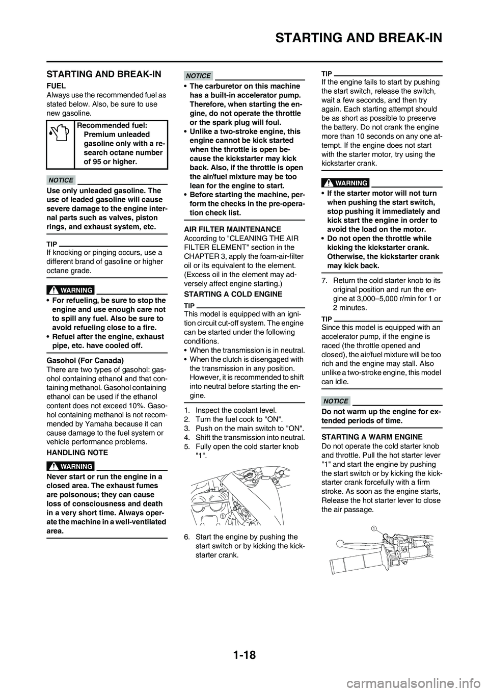
5. Fully open the cold starter knob
"1".
6. Start the engine by pushing the
start switch or by kicking the kick-
starter crank.
If the engine fails to start by pushing
the start switch, release the switch,
wait a few seconds, and then try
again. Each starting attempt should
be as short as possible to preserve
the battery. Do not crank the engine
more than 10 seconds on any one at-
tempt. If the engine does not start
with the starter motor, try using the
kickstarter crank.
• If the starter motor will not turn
when pushing the start switch,
stop pushing it immediately and
kick start the engine in order to
avoid the load on the motor.
• Do not open the throttle while
kicking the kickstarter crank.
Otherwise, the kickstarter crank
may kick back.
7. Return the cold starter knob to its
original position and run the en-
gine at 3,000–5,000 r/min for 1 or
2 minutes.
Since this model is equipped with an
accelerator pump, if the engine is
raced (the throttle opened and
closed), the air/fuel mixture will be too
rich and the engine may stall. Also
unlike a two-stroke engine, this model
can idle.
Do not warm up the engine for ex-
tended periods of time.
STARTING A WARM ENGINE
Do not operate the cold starter knob
and throttle. Pull the hot starter lever
"1" and start the engine by pushing
the start switch or by kicking the kick-
starter crank forcefully with a firm
stroke. As soon as the engine starts,
Release the hot starter lever to close
the air passage. Recommended fuel:
Premium unleaded
gasoline only with a re-
search octane number
of 95 or higher.
Page 32 of 232
2-1
GENERAL SPECIFICATIONS
SPECIFICATIONS
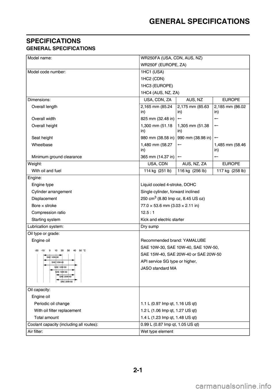
GENERAL SPECIFICATIONS
Model name: WR250FA (USA, CDN, AUS, NZ)WR250F (EUROPE, ZA)
Model code number: 1HC1 (USA) 1HC2 (CDN)
1HC3 (EUROPE)
1HC4 (AUS, NZ, ZA)
Dimensions: USA, CDN, ZA AUS, NZ EUROPE
Overall length 2,165 mm (85.24 in)2,175 mm (85.63
in)2,185 mm (86.02
in)
Overall width 825 mm (32.48 in) ←←
Overall height 1,300 mm (51.18 in)1,305 mm (51.38
in)←
Seat height 980 mm (38.58 in) 990 mm (38.98 in) ←
Wheelbase 1,480 mm (58.27 in)←
1,485 mm (58.46
in)
Minimum ground clearance 365 mm (14.37 in) ←←
Weight: USA, CDN AUS, NZ, ZA EUROPE With oil and fuel
114 kg (251 lb)116 kg (256 lb) 117 kg (258 lb)
Engine: Engine type Liquid cooled 4-stroke, DOHC
Cylinder arrangement Single cylinder, forward inclined
Displacement 250 cm
3 (8.80 Imp oz, 8.45 US oz)
Bore × stroke 77.0 × 53.6 mm (3.03 × 2.11 in)
Compression ratio 12.5 : 1
Starting system Kick and electric starter
Lubrication system: Dry sump
Oil type or grade: Engine oil Recommended brand: YAMALUBE SAE 10W-30, SAE 10W-40, SAE 10W-50,
SAE 15W-40, SAE 20W-40 or SAE 20W-50
API service SG type or higher,
JASO standard MA
Oil capacity: Engine oilPeriodic oil change 1.1 L (0.97 Imp qt, 1.16 US qt)
With oil filter replacement 1.2 L (1.06 Imp qt, 1.27 US qt)
Total amount 1.4 L (1.23 Imp qt, 1.48 US qt)
Coolant capacity (including all routes ): 0.99 L (0.87 Imp qt, 1.05 US qt)
Air filter: Wet type element
Page 73 of 232
3-14
ENGINE
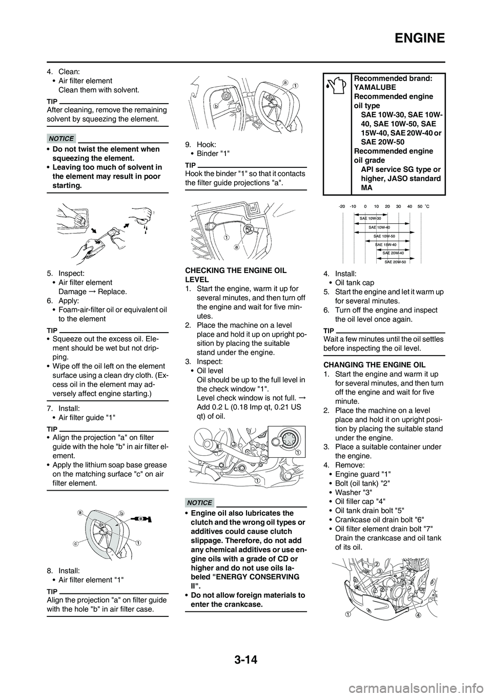
4. Clean:
• Air filter element
Clean them with solvent.
After cleaning, remove the remaining
solvent by squeezing the element.
• Do not twist the element when
squeezing the element.
• Leaving too much of solvent in
the element may result in poor
starting.
5. Inspect:
• Air filter element
Damage→Replace.
6. Apply:
• Foam-air-filter oil or equivalent oil
to the element
• Squeeze out the excess oil. Ele-
ment should be wet but not drip-
ping.
• Wipe off the oil left on the element
surface using a clean dry cloth. (Ex-
cess oil in the element may ad-
versely affect engine starting.)
7. Install:
• Air filter guide "1"
• Align the projection "a" on filter
guide with the hole "b" in air filter el-
ement.
• Apply the lithium soap base grease
on the matching surface "c" on air
filter element.
8. Install:
• Air filter element "1"
Align the projection "a" on filter guide
with the hole "b" in air filter case.
9. Hook:
• Binder "1"
Hook the binder "1" so that it contacts
the filter guide projections "a".
CHECKING THE ENGINE OIL
LEVEL
1. Start the engine, warm it up for
several minutes, and then turn off
the engine and wait for five min-
utes.
2. Place the machine on a level
place and hold it up on upright po-
sition by placing the suitable
stand under the engine.
3. Inspect:
• Oil level
Oil should be up to the full level in
the check window "1".
Level check window is not full. →
Add 0.2 L (0.18 Imp qt, 0.21 US
qt) of oil.
• Engine oil also lubricates the
clutch and the wrong oil types or
additives could cause clutch
slippage. Therefore, do not add
any chemical additives or use en-
gine oils with a grade of CD or
higher and do not use oils la-
beled "ENERGY CONSERVING
II".
• Do not allow foreign materials to
enter the crankcase.
4. Install:
• Oil tank cap
5. Start the engine and let it warm up
for several minutes.
6. Turn off the engine and inspect
the oil level once again.
Wait a few minutes until the oil settles
before inspecting the oil level.
CHANGING THE ENGINE OIL
1. Start the engine and warm it up
for several minutes, and then turn
off the engine and wait for five
minute.
2. Place the machine on a level
place and hold it on upright posi-
tion by placing the suitable stand
under the engine.
3. Place a suitable container under
the engine.
4. Remove:
• Engine guard "1"
• Bolt (oil tank) "2"
• Washer "3"
• Oil filler cap "4"
• Oil tank drain bolt "5"
• Crankcase oil drain bolt "6"
• Oil filter element drain bolt "7"
Drain the crankcase and oil tank
of its oil.
Recommended brand:
YAMALUBE
Recommended engine
oil type
SAE 10W-30, SAE 10W-
40, SAE 10W-50, SAE
15W-40, SAE 20W-40 or
SAE 20W-50
Recommended engine
oil grade
API service SG type or
higher, JASO standard
MA
Page 92 of 232
3-33
ELECTRICAL
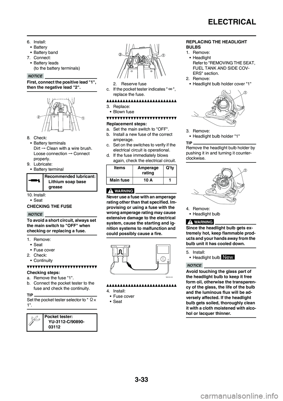
6. Install:
•Battery
• Battery band
7. Connect:
• Battery leads
(to the battery terminals)
First, connect the positive lead "1",
then the negative lead "2".
8. Check:
• Battery terminals
Dirt→Clean with a wire brush.
Loose connection→Connect
properly.
9. Lubricate:
• Battery terminal
10. Install:
• Seat
CHECKING THE FUSE
To avoid a short circuit, always set
the main switch to "OFF" when
checking or replacing a fuse.
1. Remove:
• Seat
• Fuse cover
2. Check:
• Continuity
Checking steps:
a. Remove the fuse "1".
b. Connect the pocket tester to the
fuse and check the continuity.
Set the pocket tester selector to " Ω×
1".
2. Reserve fuse
c. If the pocket tester indicates "∞",
replace the fuse.
3. Replace:
• Blown fuse
Replacement steps:
a. Set the main switch to "OFF".
b. Install a new fuse of the correct
amperage.
c. Set on the switches to verify if the
electrical circuit is operational.
d. If the fuse immediately blows
again, check the electrical circuit.
Never use a fuse with an amperage
rating other than that specified. Im-
provising or using a fuse with the
wrong amperage rating may cause
extensive damage to the electrical
system, cause the starting and ig-
nition systems to malfunction and
could possibly cause a fire.
4. Install:
• Fuse cover
•SeatREPLACING THE HEADLIGHT
BULBS
1. Remove:
• Headlight
Refer to "REMOVING THE SEAT,
FUEL TANK AND SIDE COV-
ERS" section.
2. Remove:
• Headlight bulb holder cover "1"
3. Remove:
• Headlight bulb holder "1"
Remove the headlight bulb holder by
pushing it in and turning it counter-
clockwise.
4. Remove:
• Headlight bulb
Since the headlight bulb gets ex-
tremely hot, keep flammable prod-
ucts and your hands away from the
bulb unit it has cooled down.
5. Install:
• Headlight bulb
Avoid touching the glass part of
the headlight bulb to keep it free
form oil, otherwise the transparen-
cy of the glass, the life of the bulb
and the luminous flux will be ad-
versely affected. If the headlight
bulb gets soiled, thoroughly clean
it with a cloth moistened with alco-
hol or lacquer thinner.
Recommended lubricant:
Lithium soap base
grease
Pocket tester:
YU-3112-C/90890-
03112
Items Amperage
ratingQ'ty
Main fuse 10 A 1
Page 184 of 232
6-15
FRONT BRAKE AND REAR BRAKE
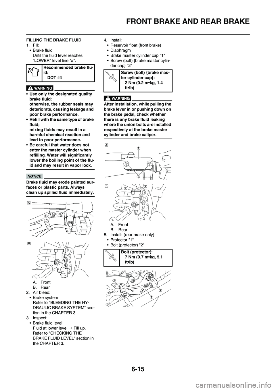
FILLING THE BRAKE FLUID
1. Fill:
• Brake fluid
Until the fluid level reaches
"LOWER" level line "a".
• Use only the designated quality
brake fluid:
otherwise, the rubber seals may
deteriorate, causing leakage and
poor brake performance.
• Refill with the same type of brake
fluid;
mixing fluids may result in a
harmful chemical reaction and
lead to poor performance.
• Be careful that water does not
enter the master cylinder when
refilling. Water will significantly
lower the boiling point of the flu-
id and may result in vapor lock.
Brake fluid may erode painted sur-
faces or plastic parts. Always
clean up spilled fluid immediately.
A. Front
B. Rear
2. Air bleed:
• Brake system
Refer to "BLEEDING THE HY-
DRAULIC BRAKE SYSTEM" sec-
tion in the CHAPTER 3.
3. Inspect:
• Brake fluid level
Fluid at lower level→Fill up.
Refer to "CHECKING THE
BRAKE FLUID LEVEL" section in
the CHAPTER 3.4. Install:
• Reservoir float (front brake)
• Diaphragm
• Brake master cylinder cap "1"
• Screw (bolt) {brake master cylin-
der cap} "2"
After installation, while pulling the
brake lever in or pushing down on
the brake pedal, check whether
there is any brake fluid leaking
where the union bolts are installed
respectively at the brake master
cylinder and brake caliper.
A. Front
B. Rear
5. Install: (rear brake only)
• Protector "1"
• Bolt (protector) "2" Recommended brake flu-
id:
DOT #4
Screw (bolt) {brake mas-
ter cylinder cap}:
2 Nm (0.2 m•kg, 1.4
ft•lb)
Bolt (protector):
7 Nm (0.7 m•kg, 5.1
ft•lb)
Page 187 of 232
6-18
FRONT FORK
HANDLING NOTE
Support the machine securely so
there is no danger of it falling over.
The front fork requires careful atten-
tion. So it is recommended that the
front fork be maintained at the deal-
ers.
To prevent an accidental explosion
of air, the following instructions
should be observed:
• The front fork with a built-in pis-
ton rod has a very sophisticated
internal construction and is par-
ticularly sensitive to foreign ma-
terial. Use enough care not to
allow any foreign material to
come in when the oil is replaced
or when the front fork is disas-
sembled and reassembled.
• Before removing the cap bolts or
front forks, be sure to extract the
air from the air chamber com-
pletely.
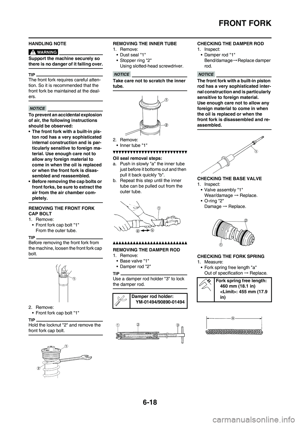
REMOVING THE FRONT FORK
CAP BOLT
1. Remove:
• Front fork cap bolt "1"
From the outer tube.
Before removing the front fork from
the machine, loosen the front fork cap
bolt.
2. Remove:
• Front fork cap bolt "1"
Hold the locknut "2" and remove the
front fork cap bolt.
REMOVING THE INNER TUBE
1. Remove:
• Dust seal "1"
• Stopper ring "2"
Using slotted-head screwdriver.
Take care not to scratch the inner
tube.
2. Remove:
• Inner tube "1"
Oil seal removal steps:
a. Push in slowly "a" the inner tube
just before it bottoms out and then
pull it back quickly "b".
b. Repeat this step until the inner
tube can be pulled out from the
outer tube.
REMOVING THE DAMPER ROD
1. Remove:
• Base valve "1"
• Damper rod "2"
Use a damper rod holder "3" to lock
the damper rod.
CHECKING THE DAMPER ROD
1. Inspect:
• Damper rod "1"
Bend/damage→Replace damper
rod.
The front fork with a built-in piston
rod has a very sophisticated inter-
nal construction and is particularly
sensitive to foreign material.
Use enough care not to allow any
foreign material to come in when
the oil is replaced or when the
front fork is disassembled and re-
assembled.
CHECKING THE BASE VALVE
1. Inspect:
• Valve assembly "1"
Wear/damage →Replace.
• O-ring "2"
Damage→ Replace.
CHECKING THE FORK SPRING
1. Measure:
• Fork spring free length "a"
Out of specification→Replace.
Damper rod holder:
YM-01494/90890-01494
Fork spring free length:
460 mm (18.1 in)
in)
Page 189 of 232
6-20
FRONT FORK
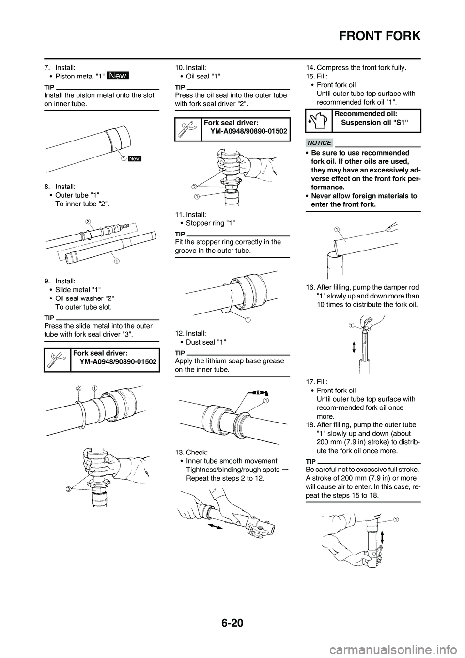
7. Install:
• Piston metal "1"
Install the piston metal onto the slot
on inner tube.
8. Install:
• Outer tube "1"
To inner tube "2".
9. Install:
• Slide metal "1"
• Oil seal washer "2"
To outer tube slot.
Press the slide metal into the outer
tube with fork seal driver "3".
10. Install:
• Oil seal "1"
Press the oil seal into the outer tube
with fork seal driver "2".
11. Install:
• Stopper ring "1"
Fit the stopper ring correctly in the
groove in the outer tube.
12. Install:
• Dust seal "1"
Apply the lithium soap base grease
on the inner tube.
13. Check:
• Inner tube smooth movement
Tightness/binding/rough spots →
Repeat the steps 2 to 12.14. Compress the front fork fully.
15. Fill:
• Front fork oil
Until outer tube top surface with
recommended fork oil "1".
• Be sure to use recommended
fork oil. If other oils are used,
they may have an excessively ad-
verse effect on the front fork per-
formance.
• Never allow foreign materials to
enter the front fork.
16. After filling, pump the damper rod
"1" slowly up and down more than
10 times to distribute the fork oil.
17. Fill:
• Front fork oil
Until outer tube top surface with
recom-mended fork oil once
more.
18. After filling, pump the outer tube
"1" slowly up and down (about
200 mm (7.9 in) stroke) to distrib-
ute the fork oil once more.
Be careful not to excessive full stroke.
A stroke of 200 mm (7.9 in) or more
will cause air to enter. In this case, re-
peat the steps 15 to 18.
Fork seal driver:
YM-A0948/90890-01502
Fork seal driver:
YM-A0948/90890-01502
Recommended oil:
Suspension oil "S1"
Page 190 of 232
6-21
FRONT FORK
19. Wait ten minutes until the air bub-
bles have been removed from the
front fork, and the oil has dis-
pense evenly in system before
setting recommended oil level.
Fill with the fork oil up to the top end
of the outer tube, or the fork oil will not
spread over to every part of the front
forks, thus making it impossible to ob-
tain the correct level.
Be sure to fill with the fork oil up to the
top of the outer tube and bleed the
front forks.
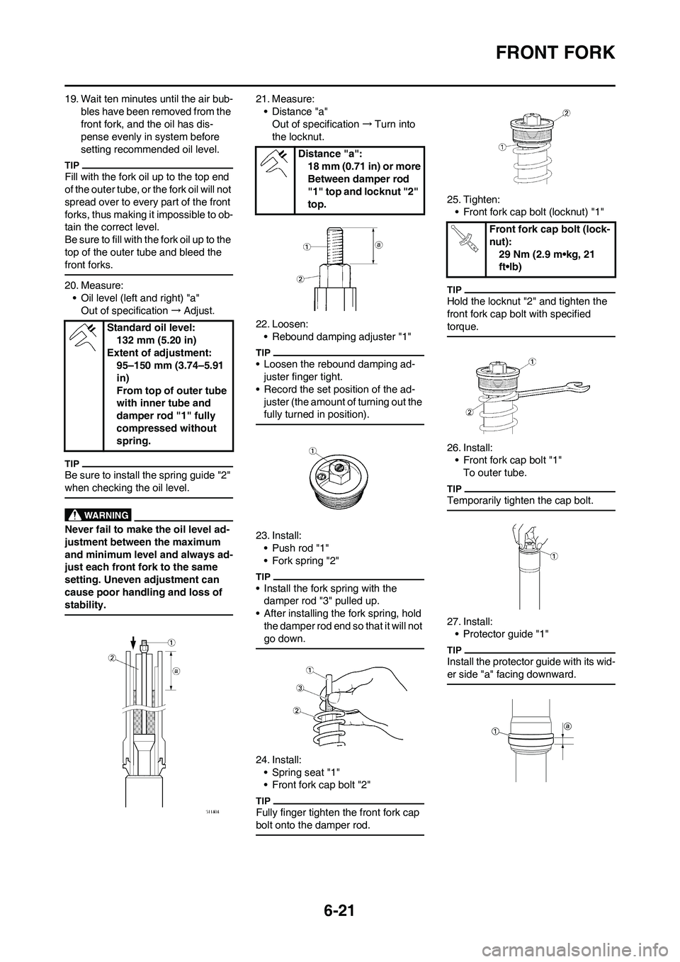
20. Measure:
• Oil level (left and right) "a"
Out of specification→Adjust.
Be sure to install the spring guide "2"
when checking the oil level.
Never fail to make the oil level ad-
justment between the maximum
and minimum level and always ad-
just each front fork to the same
setting. Uneven adjustment can
cause poor handling and loss of
stability.
21. Measure:
• Distance "a"
Out of specification→Turn into
the locknut.
22. Loosen:
• Rebound damping adjuster "1"
• Loosen the rebound damping ad-
juster finger tight.
• Record the set position of the ad-
juster (the amount of turning out the
fully turned in position).
23. Install:
• Push rod "1"
• Fork spring "2"
• Install the fork spring with the
damper rod "3" pulled up.
• After installing the fork spring, hold
the damper rod end so that it will not
go down.
24. Install:
• Spring seat "1"
• Front fork cap bolt "2"
Fully finger tighten the front fork cap
bolt onto the damper rod.
25. Tighten:
• Front fork cap bolt (locknut) "1"
Hold the locknut "2" and tighten the
front fork cap bolt with specified
torque.
26. Install:
• Front fork cap bolt "1"
To outer tube.
Temporarily tighten the cap bolt.
27. Install:
• Protector guide "1"
Install the protector guide with its wid-
er side "a" facing downward.
Standard oil level:
132 mm (5.20 in)
Extent of adjustment:
95–150 mm (3.74–5.91
in)
From top of outer tube
with inner tube and
damper rod "1" fully
compressed without
spring.
Distance "a":
18 mm (0.71 in) or more
Between damper rod
"1" top and locknut "2"
top.
Front fork cap bolt (lock-
nut):
29 Nm (2.9 m•kg, 21
ft•lb)