width YAMAHA WR 250F 2011 Owners Manual
[x] Cancel search | Manufacturer: YAMAHA, Model Year: 2011, Model line: WR 250F, Model: YAMAHA WR 250F 2011Pages: 232, PDF Size: 14.29 MB
Page 32 of 232
2-1
GENERAL SPECIFICATIONS
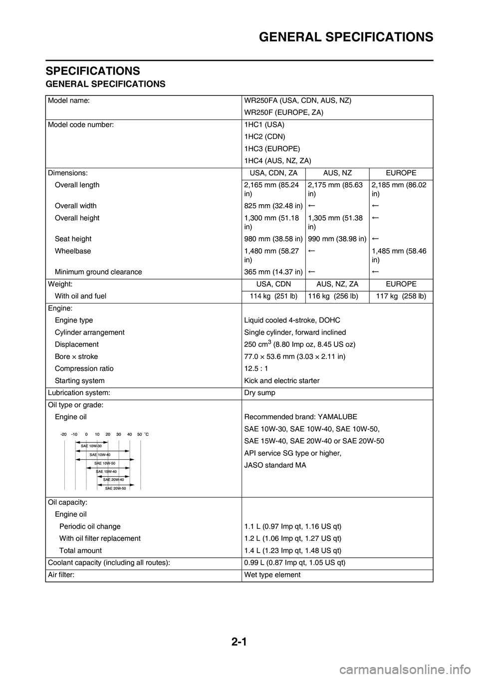
SPECIFICATIONS
GENERAL SPECIFICATIONS
Model name: WR250FA (USA, CDN, AUS, NZ)WR250F (EUROPE, ZA)
Model code number: 1HC1 (USA) 1HC2 (CDN)
1HC3 (EUROPE)
1HC4 (AUS, NZ, ZA)
Dimensions: USA, CDN, ZA AUS, NZ EUROPE
Overall length 2,165 mm (85.24 in)2,175 mm (85.63
in)2,185 mm (86.02
in)
Overall width 825 mm (32.48 in) ←←
Overall height 1,300 mm (51.18 in)1,305 mm (51.38
in)←
Seat height 980 mm (38.58 in) 990 mm (38.98 in) ←
Wheelbase 1,480 mm (58.27 in)←
1,485 mm (58.46
in)
Minimum ground clearance 365 mm (14.37 in) ←←
Weight: USA, CDN AUS, NZ, ZA EUROPE With oil and fuel
114 kg (251 lb)116 kg (256 lb) 117 kg (258 lb)
Engine: Engine type Liquid cooled 4-stroke, DOHC
Cylinder arrangement Single cylinder, forward inclined
Displacement 250 cm
3 (8.80 Imp oz, 8.45 US oz)
Bore × stroke 77.0 × 53.6 mm (3.03 × 2.11 in)
Compression ratio 12.5 : 1
Starting system Kick and electric starter
Lubrication system: Dry sump
Oil type or grade: Engine oil Recommended brand: YAMALUBE SAE 10W-30, SAE 10W-40, SAE 10W-50,
SAE 15W-40, SAE 20W-40 or SAE 20W-50
API service SG type or higher,
JASO standard MA
Oil capacity: Engine oilPeriodic oil change 1.1 L (0.97 Imp qt, 1.16 US qt)
With oil filter replacement 1.2 L (1.06 Imp qt, 1.27 US qt)
Total amount 1.4 L (1.23 Imp qt, 1.48 US qt)
Coolant capacity (including all routes ): 0.99 L (0.87 Imp qt, 1.05 US qt)
Air filter: Wet type element
Page 35 of 232
2-4
MAINTENANCE SPECIFICATIONS
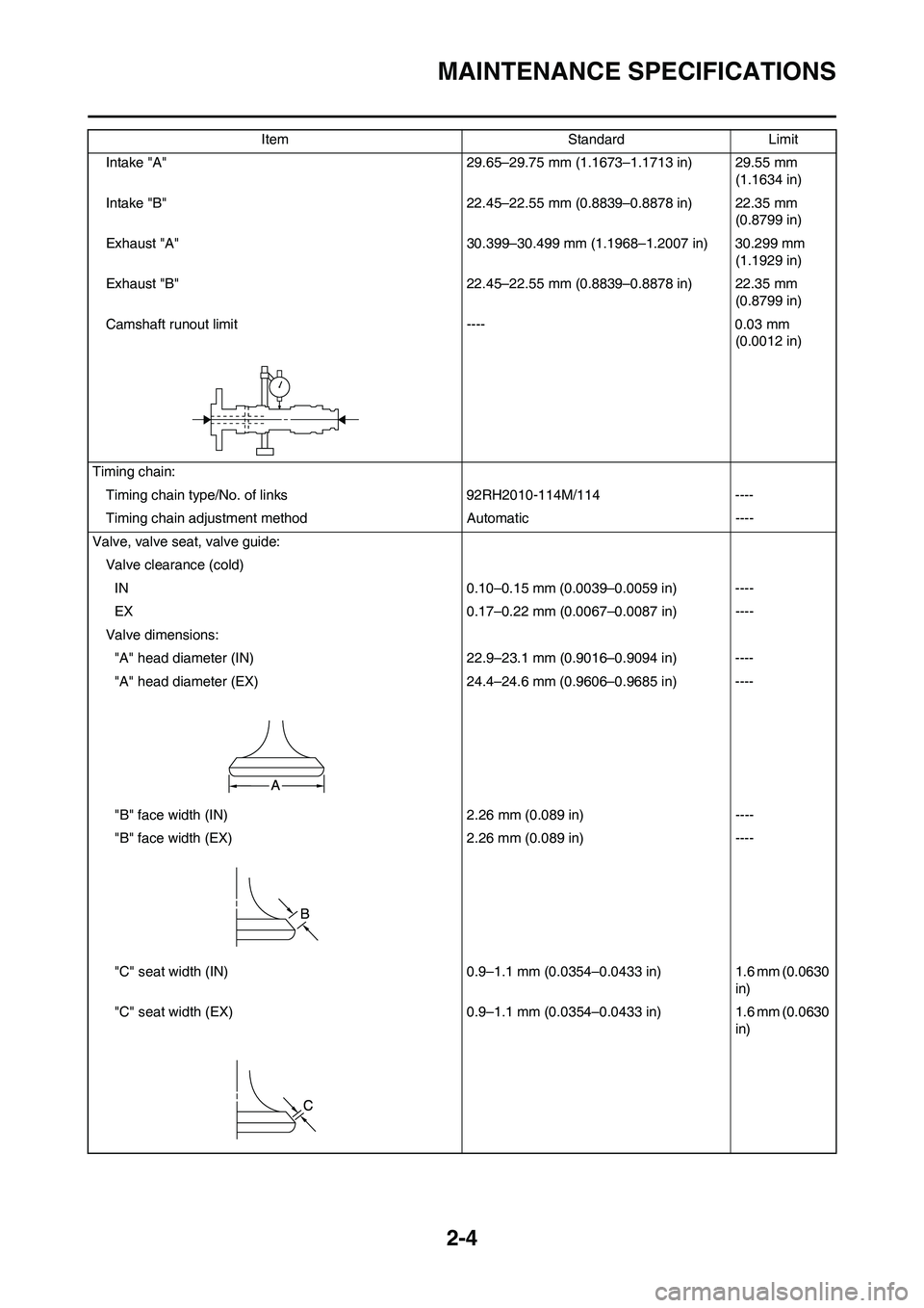
Intake "A" 29.65–29.75 mm (1.1673–1.1713 in) 29.55 mm
(1.1634 in)
Intake "B" 22.45–22.55 mm (0.8839–0.8878 in) 22.35 mm
(0.8799 in)
Exhaust "A" 30.399–30.499 mm (1.1968–1.2007 in) 30.299 mm
(1.1929 in)
Exhaust "B" 22.45–22.55 mm (0.8839–0.8878 in) 22.35 mm
(0.8799 in)
Camshaft runout limit ---- 0.03 mm
(0.0012 in)
Timing chain:
Timing chain type/No. of links 92RH2010-114M/114 ----
Timing chain adjustment method Automatic ----
Valve, valve seat, valve guide:
Valve clearance (cold)
IN 0.10–0.15 mm (0.0039–0.0059 in) ----
EX 0.17–0.22 mm (0.0067–0.0087 in) ----
Valve dimensions:
"A" head diameter (IN) 22.9–23.1 mm (0.9016–0.9094 in) ----
"A" head diameter (EX) 24.4–24.6 mm (0.9606–0.9685 in) ----
"B" face width (IN) 2.26 mm (0.089 in) ----
"B" face width (EX) 2.26 mm (0.089 in) ----
"C" seat width (IN) 0.9–1.1 mm (0.0354–0.0433 in) 1.6 mm (0.0630
in)
"C" seat width (EX) 0.9–1.1 mm (0.0354–0.0433 in) 1.6 mm (0.0630
in) Item Standard Limit
Page 36 of 232
2-5
MAINTENANCE SPECIFICATIONS
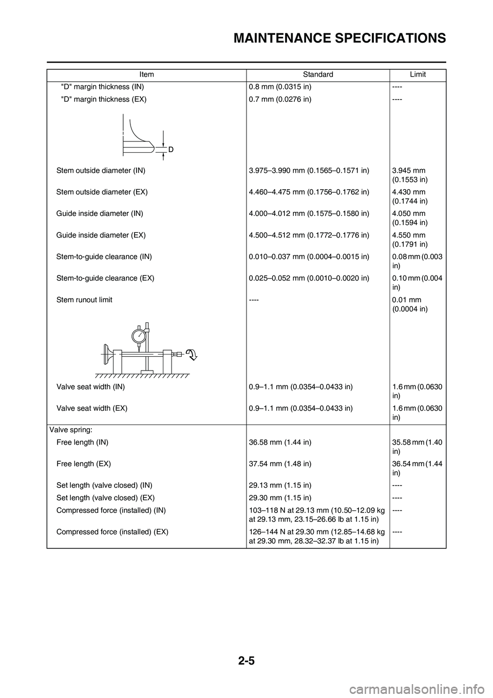
"D" margin thickness (IN) 0.8 mm (0.0315 in) ----
"D" margin thickness (EX) 0.7 mm (0.0276 in) ----
Stem outside diameter (IN) 3.975–3.990 mm (0.1565–0.1571 in) 3.945 mm
(0.1553 in)
Stem outside diameter (EX) 4.460–4.475 mm (0.1756–0.1762 in) 4.430 mm
(0.1744 in)
Guide inside diameter (IN) 4.000–4.012 mm (0.1575–0.1580 in) 4.050 mm
(0.1594 in)
Guide inside diameter (EX) 4.500–4.512 mm (0.1772–0.1776 in) 4.550 mm
(0.1791 in)
Stem-to-guide clearance (IN) 0.010–0.037 mm (0.0004–0.0015 in) 0.08 mm (0.003
in)
Stem-to-guide clearance (EX) 0.025–0.052 mm (0.0010–0.0020 in) 0.10 mm (0.004
in)
Stem runout limit ---- 0.01 mm
(0.0004 in)
Valve seat width (IN) 0.9–1.1 mm (0.0354–0.0433 in) 1.6 mm (0.0630
in)
Valve seat width (EX) 0.9–1.1 mm (0.0354–0.0433 in) 1.6 mm (0.0630
in)
Valve spring:
Free length (IN) 36.58 mm (1.44 in) 35.58 mm (1.40
in)
Free length (EX) 37.54 mm (1.48 in) 36.54 mm (1.44
in)
Set length (valve closed) (IN) 29.13 mm (1.15 in) ----
Set length (valve closed) (EX) 29.30 mm (1.15 in) ----
Compressed force (installed) (IN) 103–118 N at 29.13 mm (10.50–12.09 kg
at 29.13 mm, 23.15–26.66 lb at 1.15 in)----
Compressed force (installed) (EX) 126–144 N at 29.30 mm (12.85–14.68 kg
at 29.30 mm, 28.32–32.37 lb at 1.15 in)---- Item Standard Limit
Page 38 of 232
2-7
MAINTENANCE SPECIFICATIONS
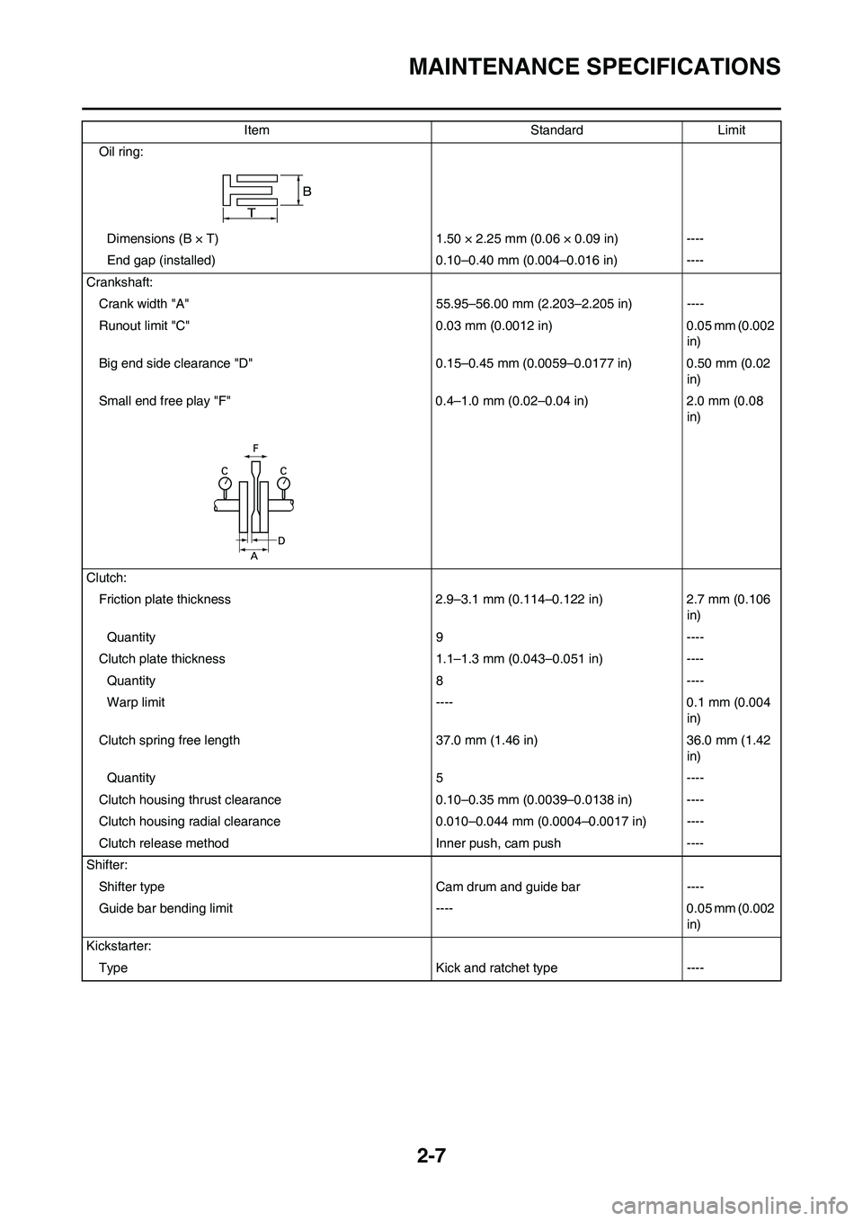
Oil ring:
Dimensions (B × T) 1.50 × 2.25 mm (0.06 × 0.09 in) ----
End gap (installed) 0.10–0.40 mm (0.004–0.016 in) ----
Crankshaft:
Crank width "A" 55.95–56.00 mm (2.203–2.205 in) ----
Runout limit "C" 0.03 mm (0.0012 in) 0.05 mm (0.002
in)
Big end side clearance "D" 0.15–0.45 mm (0.0059–0.0177 in) 0.50 mm (0.02
in)
Small end free play "F" 0.4–1.0 mm (0.02–0.04 in) 2.0 mm (0.08
in)
Clutch:
Friction plate thickness 2.9–3.1 mm (0.114–0.122 in) 2.7 mm (0.106
in)
Quantity 9 ----
Clutch plate thickness 1.1–1.3 mm (0.043–0.051 in) ----
Quantity 8 ----
Warp limit ---- 0.1 mm (0.004
in)
Clutch spring free length 37.0 mm (1.46 in) 36.0 mm (1.42
in)
Quantity 5 ----
Clutch housing thrust clearance 0.10–0.35 mm (0.0039–0.0138 in) ----
Clutch housing radial clearance 0.010–0.044 mm (0.0004–0.0017 in) ----
Clutch release method Inner push, cam push ----
Shifter:
Shifter type Cam drum and guide bar ----
Guide bar bending limit ---- 0.05 mm (0.002
in)
Kickstarter:
Type Kick and ratchet type ----Item Standard Limit
Page 39 of 232
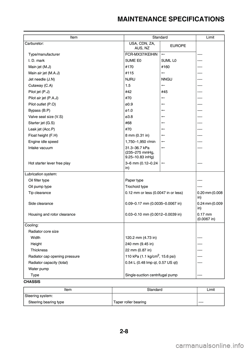
2-8
MAINTENANCE SPECIFICATIONS
CHASSISCarburetor: USA, CDN, ZA,
AUS, NZEUROPE
Type/manufacturer FCR-MX37/KEIHIN←----
I. D. mark 5UME E0 5UML L0 ----
Main jet (M.J) #170 #160 ----
Main air jet (M.A.J) #115←----
Jet needle (J.N) NJRU NNGU ----
Cutaway (C.A) 1.5←----
Pilot jet (P.J) #42 #45 ----
Pilot air jet (P.A.J) #70←----
Pilot outlet (P.O) ø0.9←----
Bypass (B.P) ø1.0←----
Valve seat size (V.S) ø3.8←----
Starter jet (G.S) #68←----
Leak jet (Acc.P) #70←----
Float height (F.H) 8 mm (0.31 in)←----
Engine idle speed 1,750–1,950 r/min←----
Intake vacuum 31.3–36.7 kPa
(235–275 mmHg,
9.25–10.83 inHg)←----
Hot starter lever free play 3–6 mm (0.12–0.24
in)←----
Lubrication system:
Oil filter type Paper type ----
Oil pump type Trochoid type ----
Tip clearance 0.12 mm or less (0.0047 in or less) 0.20 mm (0.008
in)
Side clearance 0.09–0.17 mm (0.0035–0.0067 in) 0.24 mm (0.009
in)
Housing and rotor clearance 0.03–0.10 mm (0.0012–0.0039 in) 0.17 mm
(0.0067 in)
Cooling:
Radiator core size
Width 120.2 mm (4.73 in) ----
Height 240 mm (9.45 in) ----
Thickness 22 mm (0.87 in) ----
Radiator cap opening pressure 110 kPa (1.1 kg/cm
2, 15.6 psi) ----
Radiator capacity (total) 0.54 L (0.48 Imp qt, 0.57 US qt) ----
Water pump
Type Single-suction centrifugal pump ----Item Standard Limit
Item Standard Limit
Steering system:
Steering bearing typeTaper roller bearing ----
Page 120 of 232
5-17
CAMSHAFTS
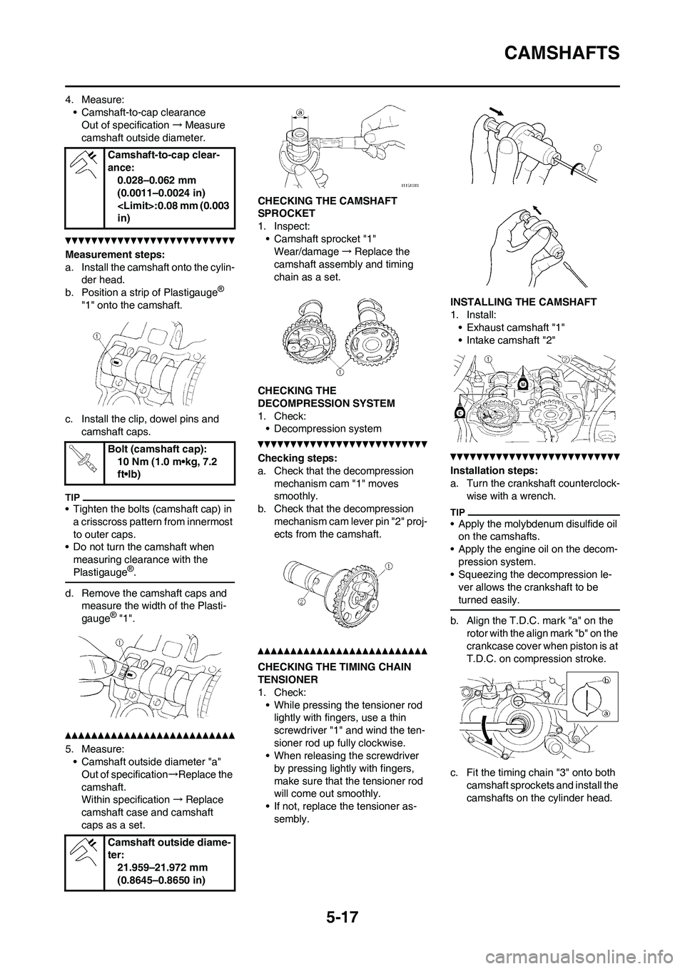
4. Measure:
• Camshaft-to-cap clearance
Out of specification→Measure
camshaft outside diameter.
Measurement steps:
a. Install the camshaft onto the cylin-
der head.
b. Position a strip of Plastigauge
®
"1" onto the camshaft.
c. Install the clip, dowel pins and
camshaft caps.
• Tighten the bolts (camshaft cap) in
a crisscross pattern from innermost
to outer caps.
• Do not turn the camshaft when
measuring clearance with the
Plastigauge
®.
d. Remove the camshaft caps and
measure the width of the Plasti-
gauge
® "1".
5. Measure:
• Camshaft outside diameter "a"
Out of specification→Replace the
camshaft.
Within specification→Replace
camshaft case and camshaft
caps as a set.CHECKING THE CAMSHAFT
SPROCKET
1. Inspect:
• Camshaft sprocket "1"
Wear/damage→Replace the
camshaft assembly and timing
chain as a set.
CHECKING THE
DECOMPRESSION SYSTEM
1. Check:
• Decompression system
Checking steps:
a. Check that the decompression
mechanism cam "1" moves
smoothly.
b. Check that the decompression
mechanism cam lever pin "2" proj-
ects from the camshaft.
CHECKING THE TIMING CHAIN
TENSIONER
1. Check:
• While pressing the tensioner rod
lightly with fingers, use a thin
screwdriver "1" and wind the ten-
sioner rod up fully clockwise.
• When releasing the screwdriver
by pressing lightly with fingers,
make sure that the tensioner rod
will come out smoothly.
• If not, replace the tensioner as-
sembly.INSTALLING THE CAMSHAFT
1. Install:
• Exhaust camshaft "1"
• Intake camshaft "2"
Installation steps:
a. Turn the crankshaft counterclock-
wise with a wrench.
• Apply the molybdenum disulfide oil
on the camshafts.
• Apply the engine oil on the decom-
pression system.
• Squeezing the decompression le-
ver allows the crankshaft to be
turned easily.
b. Align the T.D.C. mark "a" on the
rotor with the align mark "b" on the
crankcase cover when piston is at
T.D.C. on compression stroke.
c. Fit the timing chain "3" onto both
camshaft sprockets and install the
camshafts on the cylinder head. Camshaft-to-cap clear-
ance:
0.028–0.062 mm
(0.0011–0.0024 in)
in)
Bolt (camshaft cap):
10 Nm (1.0 m•kg, 7.2
ft•lb)
Camshaft outside diame-
ter:
21.959–21.972 mm
(0.8645–0.8650 in)
Page 123 of 232
5-20
CYLINDER HEAD
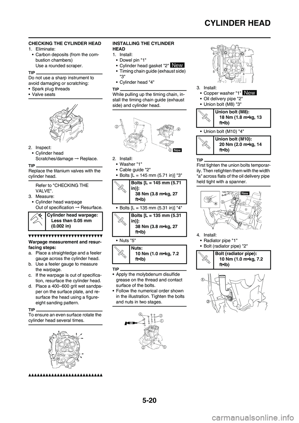
CHECKING THE CYLINDER HEAD
1. Eliminate:
• Carbon deposits (from the com-
bustion chambers)
Use a rounded scraper.
Do not use a sharp instrument to
avoid damaging or scratching:
• Spark plug threads
• Valve seats
2. Inspect:
• Cylinder head
Scratches/damage→Replace.
Replace the titanium valves with the
cylinder head.
Refer to "CHECKING THE
VALVE".
3. Measure:
• Cylinder head warpage
Out of specification→Resurface.
Warpage measurement and resur-
facing steps:
a. Place a straightedge and a feeler
gauge across the cylinder head.
b. Use a feeler gauge to measure
the warpage.
c. If the warpage is out of specifica-
tion, resurface the cylinder head.
d. Place a 400–600 grit wet sandpa-
per on the surface plate, and re-
surface the head using a figure-
eight sanding pattern.
To ensure an even surface rotate the
cylinder head several times.
INSTALLING THE CYLINDER
HEAD
1. Install:
• Dowel pin "1"
• Cylinder head gasket "2"
• Timing chain guide (exhaust side)
"3"
• Cylinder head "4"
While pulling up the timing chain, in-
stall the timing chain guide (exhaust
side) and cylinder head.
2. Install:
• Washer "1"
• Cable guide "2"
• Bolts [L = 145 mm (5.71 in)] "3"
• Bolts [L = 135 mm (5.31 in)] "4"
•Nuts "5"
• Apply the molybdenum disulfide
grease on the thread and contact
surface of the bolts.
• Follow the numerical order shown
in the illustration. Tighten the bolts
and nuts in two stages.
3. Install:
• Copper washer "1"
• Oil delivery pipe "2"
• Union bolt (M8) "3"
• Union bolt (M10) "4"
First tighten the union bolts temporar-
ily. Then retighten them with the width
"a" across flats of the oil delivery pipe
held tight with a spanner.
4. Install:
• Radiator pipe "1"
• Bolt (radiator pipe) "2" Cylinder head warpage:
Less than 0.05 mm
(0.002 in)
Bolts [L = 145 mm (5.71
in)]:
38 Nm (3.8 m•kg, 27
ft•lb)
Bolts [L = 135 mm (5.31
in)]:
38 Nm (3.8 m•kg, 27
ft•lb)
Nuts:
10 Nm (1.0 m•kg, 7.2
ft•lb)
Union bolt (M8):
18 Nm (1.8 m•kg, 13
ft•lb)
Union bolt (M10):
20 Nm (2.0 m•kg, 14
ft•lb)
Bolt (radiator pipe):
10 Nm (1.0 m•kg, 7.2
ft•lb)
Page 125 of 232
5-22
VALVES AND VALVE SPRINGS
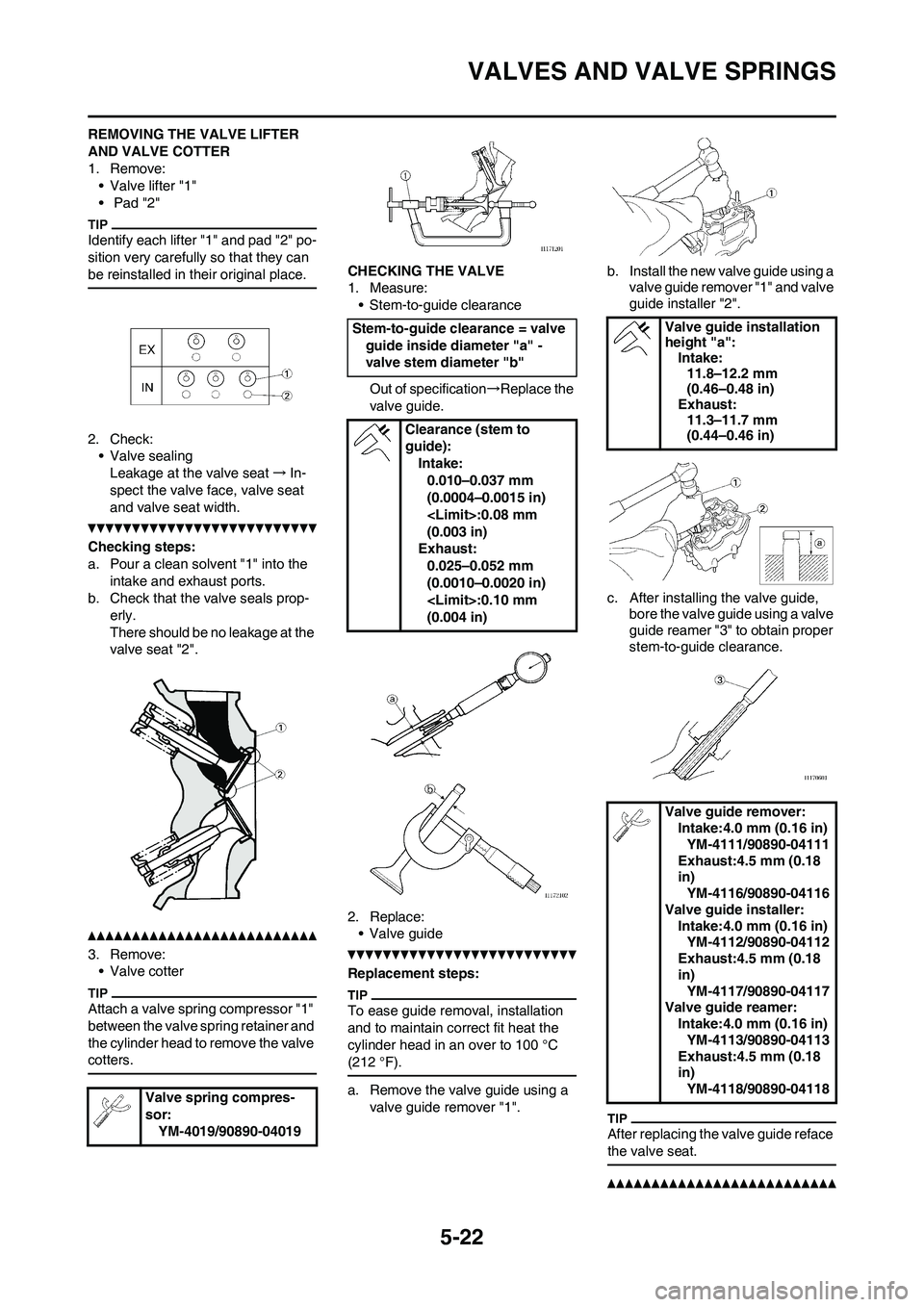
REMOVING THE VALVE LIFTER
AND VALVE COTTER
1. Remove:• Valve lifter "1"
• Pad "2"
Identify each lifter "1" and pad "2" po-
sition very carefully so that they can
be reinstalled in their original place.
2. Check:• Valve sealingLeakage at the valve seat →In-
spect the valve face, valve seat
and valve seat width.
Checking steps:
a. Pour a clean solvent "1" into the intake and exhaust ports.
b. Check that the valve seals prop- erly.
There should be no leakage at the
valve seat "2".
3. Remove:• Valve cotter
Attach a valve spring compressor "1"
between the valve spring retainer and
the cylinder head to remove the valve
cotters.
CHECKING THE VALVE
1. Measure:
• Stem-to-guide clearance
Out of specification →Replace the
valve guide.
2. Replace: • Valve guide
Replacement steps:
To ease guide removal, installation
and to maintain correct fit heat the
cylinder head in an over to 100 °C
(212 °F).
a. Remove the valve guide using a valve guide remover "1". b. Install the new valve guide using a
valve guide remover "1" and valve
guide installer "2".
c. After installing the valve guide, bore the valve guide using a valve
guide reamer "3" to obtain proper
stem-to-guide clearance.
After replacing the valve guide reface
the valve seat.
Valve spring compres-
sor:
YM-4019/90890-04019
Stem-to-guide clearance = valve guide inside diameter "a" -
valve stem diameter "b"
Clearance (stem to
guide):Intake:0.010–0.037 mm
(0.0004–0.0015 in)
(0.003 in)
Exhaust:
0.025–0.052 mm
(0.0010–0.0020 in)
(0.004 in)Valve guide installation
height "a": Intake:
11.8–12.2 mm
(0.46–0.48 in)
Exhaust:
11.3–11.7 mm
(0.44–0.46 in)
Valve guide remover: Intake:4.0 mm (0.16 in)YM-4111/90890-04111
Exhaust:4.5 mm (0.18
in) YM-4116/90890-04116
Valve guide installer: Intake:4.0 mm (0.16 in)YM-4112/90890-04112
Exhaust:4.5 mm (0.18
in) YM-4117/90890-04117
Valve guide reamer: Intake:4.0 mm (0.16 in)YM-4113/90890-04113
Exhaust:4.5 mm (0.18
in) YM-4118/90890-04118
Page 126 of 232
5-23
VALVES AND VALVE SPRINGS
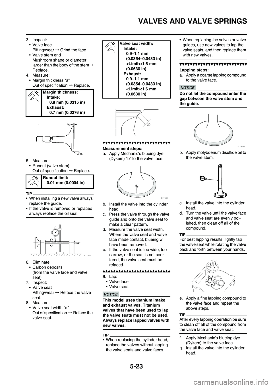
3. Inspect:• Valve facePitting/wear →Grind the face.
• Valve stem end
Mushroom shape or diameter
larger than the body of the stem →
Replace.
4. Measure: • Margin thickness "a"Out of specification →Replace.
5. Measure: • Runout (valve stem)Out of specification →Replace.
• When installing a new valve always
replace the guide.
• If the valve is removed or replaced always replace the oil seal.
6. Eliminate:• Carbon deposits(from the valve face and valve
seat)
7. Inspect: • Valve seat
Pitting/wear →Reface the valve
seat.
8. Measure:
• Valve seat width "a"Out of specification →Reface the
valve seat.
Measurement steps:
a. Apply Mechanic's blueing dye
(Dykem) "b" to the valve face.
b. Install the valve into the cylinder head.
c. Press the valve through the valve
guide and onto the valve seat to
make a clear pattern.
d. Measure the valve seat width.
Where the valve seat and valve
face made contact, blueing will
have been removed.
e. If the valve seat is too wide, too narrow, or the seat is not cen-
tered, the valve seat must be
refaced.
9. Lap: • Valve face
• Valve seat
This model uses titanium intake
and exhaust valves. Titanium
valves that have been used to lap
the valve seats must not be used.
Always replace lapped valves with
new valves.
• When replacing the cylinder head, replace the valves without lapping
the valve seats and valve faces. • When replacing the valves or valve
guides, use new valves to lap the
valve seats, and then replace them
with new valves.
Lapping steps:
a. Apply a coarse lapping compound to the valve face.
Do not let the co mpound enter the
gap between the valve stem and
the guide.
b. Apply molybdenum disulfide oil to
the valve stem.
c. Install the valve into the cylinder head.
d. Turn the valve until the valve face
and valve seat are evenly pol-
ished, then clean off all of the
compound.
For best lapping results, lightly tap
the valve seat while rotating the valve
back and forth between your hands.
e. Apply a fine lapping compound to the valve face and repeat the
above steps.
After every lapping operation be sure
to clean off all of the compound from
the valve face and valve seat.
f. Apply Mechanic's blueing dye (Dykem) to the valve face.
g. Install the valve into the cylinder
head.
Margin thickness:
Intake:0.8 mm (0.0315 in)
Exhaust:
0.7 mm (0.0276 in)
Runout limit: 0.01 mm (0.0004 in)
Valve seat width:Intake:0.9–1.1 mm
(0.0354–0.0433 in)
(0.0630 in)
Exhaust: 0.9–1.1 mm
(0.0354–0.0433 in)
(0.0630 in)
Page 127 of 232
5-24
VALVES AND VALVE SPRINGS
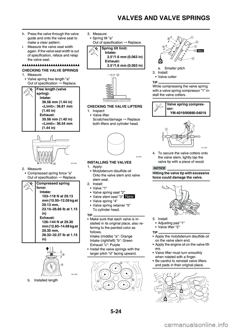
h. Press the valve through the valve guide and onto the valve seat to
make a clear pattern.
i. Measure the valve seat width
again. If the valve seat width is out
of specification, reface and relap
the valve seat.
CHECKING THE VALVE SPRINGS
1. Measure:• Valve spring free length "a"Out of specification →Replace.
2. Measure: • Compressed spring force "a"Out of specification →Replace.
b. Installed length 3. Measure:
• Spring tilt "a"Out of specification →Replace.
CHECKING THE VALVE LIFTERS
1. Inspect: • Valve lifterScratches/damage →Replace
both lifters and cylinder head.
INSTALLING THE VALVES
1. Apply: • Molybdenum disulfide oilOnto the valve stem and valve
stem seal.
2. Install: • Valve "1"
• Valve spring seat "2"
• Valve stem seal "3"
• Valve spring "4"
• Valve spring retainer "5"
To cylinder head.
• Make sure that each valve is in-stalled in its original place, also re-
ferring to the painted color as
follows.
Intake (middle) "a": Orange
Intake (right/left) "b": Green
Exhaust "c": Purple
• Install the valve springs with the larger pitch "d" facing upward.
e. Smaller pitch
3. Install:
• Valve cotter
While compressing the valve spring
with a valve spring compressor "1" in-
stall the valve cotters.
4. To secure the valve cotters onto the valve stem, lightly tap the
valve tip with a piece of wood.
Hitting the valve tip with excessive
force could damage the valve.
5. Install:• Adjusting pad "1"
• Valve lifter "2"
• Apply the molybdenum disulfide oil on the valve stem end.
• Apply the engine oil on the valve lift- ers.
• Valve lifter must turn smoothly when rotated with a finger.
• Be careful to reinstall valve lifters and pads in their original place.
Free length (valve
spring):
Intake:36.58 mm (1.44 in)
(1.45 in)
Exhaust:
35.58 mm (1.40 in)
(1.44 in)
Compressed spring
force: Intake:103–118 N at 29.13
mm (10.50–12.09 kg at
29.13 mm,
23.15–26.66 lb at 1.15
in)
Exhaust: 126–144 N at 29.30
mm (12.85–14.68 kg at
29.30 mm,
28.32–32.37 lb at 1.15
in)
Spring tilt limit: Intake:
2.5°/1.6 mm (0.063 in)
Exhaust: 2.5°/1.6 mm (0.063 in)
Valve spring compres-
sor:
YM-4019/90890-04019