check engine YAMAHA WR 250F 2012 Owners Manual
[x] Cancel search | Manufacturer: YAMAHA, Model Year: 2012, Model line: WR 250F, Model: YAMAHA WR 250F 2012Pages: 232, PDF Size: 13.32 MB
Page 6 of 232
FOREWORD
INTRODUCTION
Congratulations on your purchase of
a Yamaha WR series. This model is
the culmination of Yamaha's vast ex-
perience in the production of paceset-
ting racing machines. It represents
the highest grade of craftsmanship
and reliability that have made Yama-
ha a leader.
This manual explains operation, in-
spection, basic maintenance and tun-
ing of your machine. If you have any
questions about this manual or your
machine, please contact your Yama-
ha dealer.
For Canada
The design and manufacture of this
Yamaha machine fully comply with
the emissions standards for clean air
applicable at the date of manufacture.
Yamaha has met these standards
without reducing the performance or
economy of operation of the machine.
To maintain these high standards, it
is important that you and your Yama-
ha dealer pay close attention to the
recommended maintenance sched-
ules and operating instructions con-
tained within this manual.
Yamaha continually seeks advance-
ments in product design and quality.
Therefore, while this manual contains
the most current product information
available at the time of printing, there
may be minor discrepancies between
your machine and this manual. If you
have any questions concerning this
manual, please consult your Yamaha
dealer.
PLEASE READ THIS MANUAL
CAREFULLY AND COMPLETELY
BEFORE OPERATING THIS MA-
CHINE. DO NOT ATTEMPT TO OP-
ERATE THIS MACHINE UNTIL YOU
HAVE ATTAINED A SATISFACTO-
RY KNOWLEDGE OF ITS CON-
TROLS AND OPERATING
FEATURES AND UNTIL YOU HAVE
BEEN TRAINED IN SAFE AND
PROPER RIDING TECHNIQUES.
REGULAR INSPECTIONS AND
CAREFUL MAINTENANCE,
ALONG WITH GOOD RIDING
SKILLS, WILL ENSURE THAT YOU
SAFETY ENJOY THE CAPABILI-
TIES AND THE RELIABILITY OF
THIS MACHINE.
IMPORTANT MANUAL
INFORMATION
Particularly important information is
distinguished in this manual by the
following notations.
This is the safety alert symbol. It is
used to alert you to potential per-
sonal injury hazards. Obey all safe-
ty messages that follow this
symbol to avoid possible injury or
death.
A WARNING indicates a hazardous
situation which, if not avoided,
could result in death or serious in-
jury.
A NOTICE indicates special pre-
cautions that must be taken to
avoid damage to the vehicle or oth-
er property.
A TIP provides key information to
make procedures easier or clearer.
SAFETY INFORMATION
For Canada
This machine is designed for off-road
use only. It is illegal for this machine
to be operated on any public street,
road, or highway. Off-road use on
public lands may be illegal. Please
check local regulations before riding.
Except for Canada
THIS MACHINE IS DESIGNED
STRICTLY FOR COMPETITION
USE, ONLY ON A CLOSED
COURSE. It is illegal for this machine
to be operated on any public street,
road, or highway. Off-road use on
public lands may also be illegal.
Please check local regulations before
riding.
• THIS MACHINE IS TO BE OPER-
ATED BY AN EXPERIENCED RID-
ER ONLY.
Do not attempt to operate this ma-
chine at maximum power until you
are totally familiar with its character-
istics.
• THIS MACHINE IS DESIGNED TO
BE RIDDEN BY THE OPERATOR
ONLY.
Do not carry passengers on this
machine.• ALWAYS WEAR PROTECTIVE
APPAREL.
When operating this machine, al-
ways wear an approved helmet with
goggles or a face shield. Also wear
heavy boots, gloves, and protective
clothing. Always wear proper fitting
clothing that will not be caught in
any of the moving parts or controls
of the machine.
• ALWAYS MAINTAIN YOUR MA-
CHINE IN PROPER WORKING
ORDER.
For safety and reliability, the ma-
chine must be properly maintained.
Always perform the pre-operation
checks indicated in this manual.
Correcting a mechanical problem
before you ride may prevent an ac-
cident.
• GASOLINE IS HIGHLY FLAMMA-
BLE.
Always turn off the engine while re-
fueling. Take care to not spill any
gasoline on the engine or exhaust
system. Never refuel in the vicinity
of an open flame, or while smoking.
• GASOLINE CAN CAUSE INJURY.
If you should swallow some gaso-
line, inhale excess gasoline vapors,
or allow any gasoline to get into
your eyes, contact a doctor immedi-
ately. If any gasoline spills onto
your skin or clothing, immediately
wash skin areas with soap and wa-
ter, and change your clothes.
• ONLY OPERATE THE MACHINE
IN AN AREA WITH ADEQUATE
VENTILATION.
Never start the engine or let it run
for any length of time in an enclosed
area. Exhaust fumes are poison-
ous. These fumes contain carbon
monoxide, which by itself is odor-
less and colorless. Carbon monox-
ide is a dangerous gas which can
cause unconsciousness or can be
lethal.
• PARK THE MACHINE CAREFUL-
LY; TURN OFF THE ENGINE.
Always turn off the engine if you are
going to leave the machine. Do not
park the machine on a slope or soft
ground as it may fall over.
• THE ENGINE, EXHAUST PIPE,
MUFFLER, AND OIL TANK WILL
BE VERY HOT AFTER THE EN-
GINE HAS BEEN RUN.
Be careful not to touch them or to
allow any clothing item to contact
them during inspection or repair.
Page 10 of 232

CONTENTS
CHAPTER 1
GENERAL INFOR-
MATION
LOCATION OF
IMPORTANT LABELS ..... 1-1
DESCRIPTION ................. 1-5
CONSUMER
INFORMATION................. 1-6
INCLUDED PARTS .......... 1-6
IMPORTANT
INFORMATION................. 1-6
CHECKING OF
CONNECTION .................. 1-7
SPECIAL TOOLS ............. 1-8
CONTROL FUNCTIONS.. 1-12
MULTI-FUNCTION
DISPLAY ........................ 1-13
STARTING AND
BREAK-IN ...................... 1-18
TORQUE-CHECK
POINTS........................... 1-20
CLEANING AND
STORAGE ...................... 1-21
CHAPTER 2
SPECIFICATIONS
GENERAL
SPECIFICATIONS ............ 2-1
MAINTENANCE
SPECIFICATIONS ............ 2-3
TIGHTENING
TORQUES ...................... 2-12
LUBRICATION
DIAGRAMS .................... 2-19
CABLE ROUTING
DIAGRAM ....................... 2-21
CHAPTER 3
REGULAR INSPEC-
TION AND AD-
JUSTMENTS
PERIODIC MAINTENANCE
CHART FOR THE EMISSION
CONTROL SYSTEM (For
Canada) ............................ 3-1
GENERAL MAINTENANCE
AND LUBRICATION CHART
(For Canada) .................... 3-2
MAINTENANCE INTER-
VALS FOR COMPETITION
USE ................................... 3-3
PRE-OPERATION
INSPECTION AND
MAINTENANCE................ 3-7
ENGINE ............................ 3-8
CHASSIS ........................ 3-19
ELECTRICAL ................. 3-29
CHAPTER 4
TUNING
ENGINE
(Except for Canada) ........ 4-1
CHASSIS .......................... 4-5
CHAPTER 5
ENGINE
RADIATOR ....................... 5-1
CARBURETOR................. 5-4
AIR INDICTOIN
SYSTEM ......................... 5-12
CAMSHAFTS.................. 5-14
CYLINDER HEAD........... 5-19
VALVES AND VALVE
SPRINGS ........................ 5-21
CYLINDER AND
PISTON ........................... 5-25
CLUTCH ......................... 5-29OIL FILTER ELEMENT
AND WATER PUMP .......5-34
BALANCER ....................5-39
OIL PUMP .......................5-41
KICK SHAFT AND SHIFT
SHAFT ............................5-44
AC MAGNETO AND
STARTER CLUTCH........5-49
ENGINE REMOVAL........5-54
CRANKCASE AND
CRANKSHAFT ...............5-58
TRANSMISSION,
SHIFT CAM AND
SHIFT FORK ...................5-64
CHAPTER 6
CHASSIS
FRONT WHEEL AND
REAR WHEEL ..................6-1
FRONT BRAKE AND
REAR BRAKE ..................6-6
FRONT FORK .................6-16
HANDLEBAR..................6-23
STEERING ......................6-27
SWINGARM ....................6-31
REAR SHOCK
ABSORBER ....................6-36
CHAPTER 7
ELECTRICAL
ELECTRICAL COMPO-
NENTS AND WIRING
DIAGRAM .........................7-1
IGNITION SYSTEM...........7-3
ELECTRIC STARTING
SYSTEM............................7-5
CHARGING SYSTEM .....7-13
THROTTLE POSITION
SENSOR SYSTEM .........7-15
LIGHTING SYSTEM .......7-18
SIGNALING SYSTEM.....7-20
Page 15 of 232
1-5
DESCRIPTION
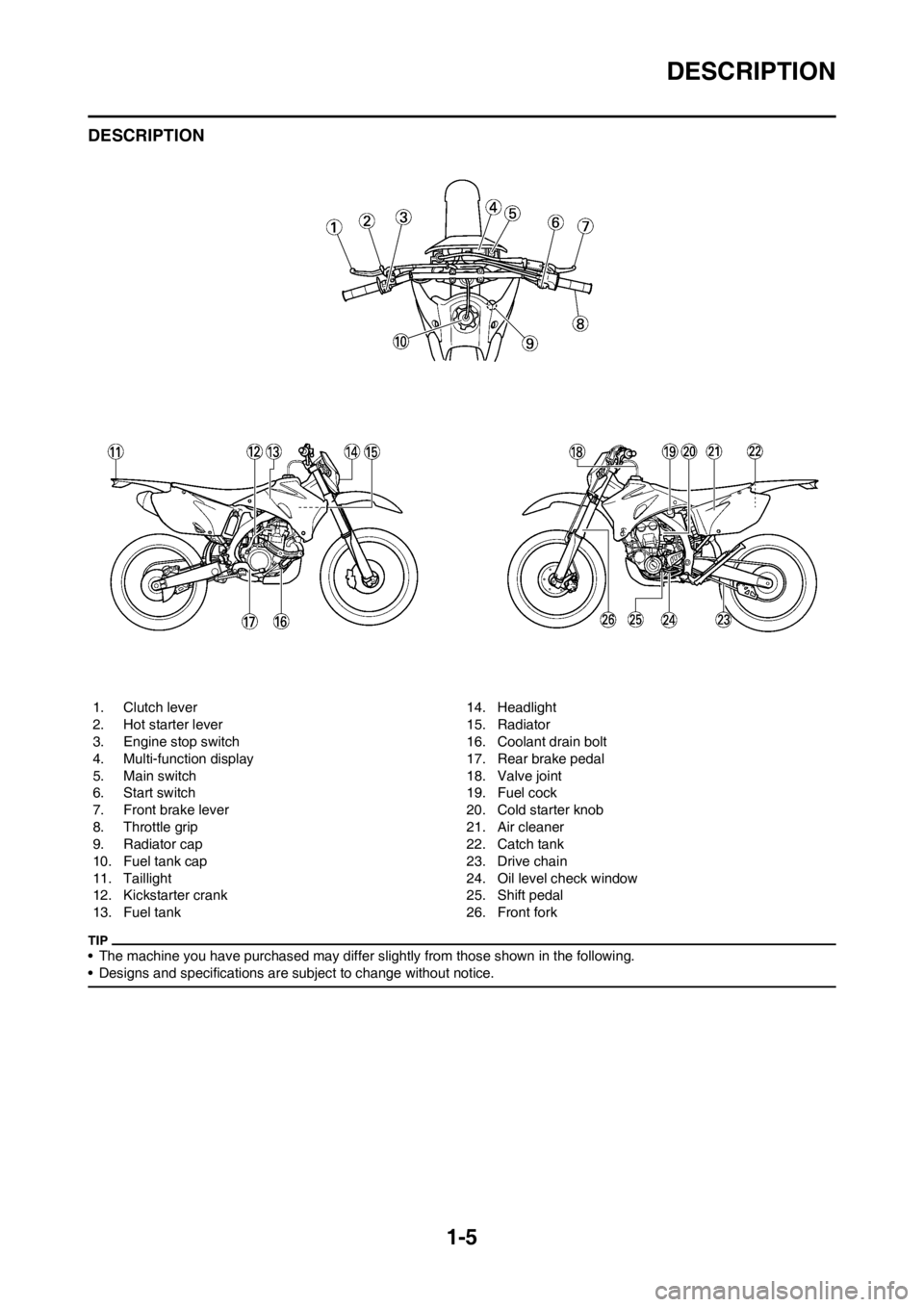
DESCRIPTION
• The machine you have purchased may differ slightly from those shown in the following.
• Designs and specifications are subject to change without notice.
1. Clutch lever
2. Hot starter lever
3. Engine stop switch
4. Multi-function display
5. Main switch
6. Start switch
7. Front brake lever
8. Throttle grip
9. Radiator cap
10. Fuel tank cap
11. Taillight
12. Kickstarter crank
13. Fuel tank14. Headlight
15. Radiator
16. Coolant drain bolt
17. Rear brake pedal
18. Valve joint
19. Fuel cock
20. Cold starter knob
21. Air cleaner
22. Catch tank
23. Drive chain
24. Oil level check window
25. Shift pedal
26. Front fork
Page 28 of 232
1-18
STARTING AND BREAK-IN
STARTING AND BREAK-IN
FUEL
Always use the recommended fuel as
stated below. Also, be sure to use
new gasoline.
Use only unleaded gasoline. The
use of leaded gasoline will cause
severe damage to the engine inter-
nal parts such as valves, piston
rings, and exhaust system, etc.
If knocking or pinging occurs, use a
different brand of gasoline or higher
octane grade.
• For refueling, be sure to stop the
engine and use enough care not
to spill any fuel. Also be sure to
avoid refueling close to a fire.
• Refuel after the engine, exhaust
pipe, etc. have cooled off.
Gasohol (For Canada)
There are two types of gasohol: gas-
ohol containing ethanol and that con-
taining methanol. Gasohol containing
ethanol can be used if the ethanol
content does not exceed 10%. Gaso-
hol containing methanol is not recom-
mended by Yamaha because it can
cause damage to the fuel system or
vehicle performance problems.
HANDLING NOTE
Never start or run the engine in a
closed area. The exhaust fumes
are poisonous; they can cause
loss of consciousness and death
in a very short time. Always oper-
ate the machine in a well-ventilated
area.
• The carburetor on this machine
has a built-in accelerator pump.
Therefore, when starting the en-
gine, do not operate the throttle
or the spark plug will foul.
• Unlike a two-stroke engine, this
engine cannot be kick started
when the throttle is open be-
cause the kickstarter may kick
back. Also, if the throttle is open
the air/fuel mixture may be too
lean for the engine to start.
• Before starting the machine, per-
form the checks in the pre-opera-
tion check list.
AIR FILTER MAINTENANCE
According to "CLEANING THE AIR
FILTER ELEMENT" section in the
CHAPTER 3, apply the foam-air-filter
oil or its equivalent to the element.
(Excess oil in the element may ad-
versely affect engine starting.)
STARTING A COLD ENGINE
This model is equipped with an igni-
tion circuit cut-off system. The engine
can be started under the following
conditions.
• When the transmission is in neutral.
• When the clutch is disengaged with
the transmission in any position.
However, it is recommended to shift
into neutral before starting the en-
gine.
1. Inspect the coolant level.
2. Turn the fuel cock to "ON".
3. Push on the main switch to "ON".
4. Shift the transmission into neutral.
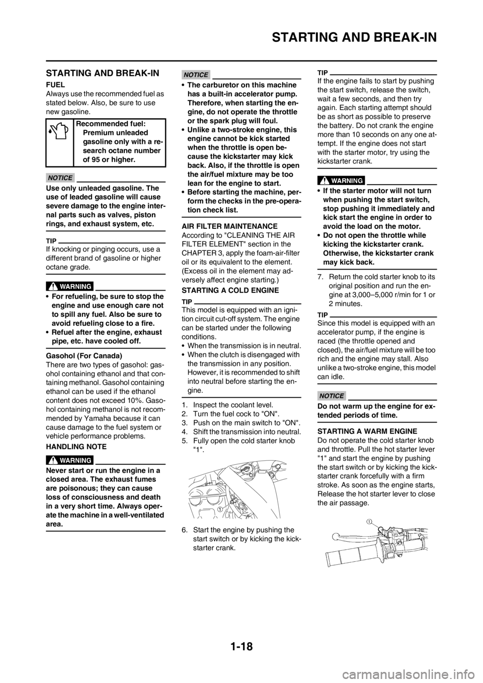
5. Fully open the cold starter knob
"1".
6. Start the engine by pushing the
start switch or by kicking the kick-
starter crank.
If the engine fails to start by pushing
the start switch, release the switch,
wait a few seconds, and then try
again. Each starting attempt should
be as short as possible to preserve
the battery. Do not crank the engine
more than 10 seconds on any one at-
tempt. If the engine does not start
with the starter motor, try using the
kickstarter crank.
• If the starter motor will not turn
when pushing the start switch,
stop pushing it immediately and
kick start the engine in order to
avoid the load on the motor.
• Do not open the throttle while
kicking the kickstarter crank.
Otherwise, the kickstarter crank
may kick back.
7. Return the cold starter knob to its
original position and run the en-
gine at 3,000–5,000 r/min for 1 or
2 minutes.
Since this model is equipped with an
accelerator pump, if the engine is
raced (the throttle opened and
closed), the air/fuel mixture will be too
rich and the engine may stall. Also
unlike a two-stroke engine, this model
can idle.
Do not warm up the engine for ex-
tended periods of time.
STARTING A WARM ENGINE
Do not operate the cold starter knob
and throttle. Pull the hot starter lever
"1" and start the engine by pushing
the start switch or by kicking the kick-
starter crank forcefully with a firm
stroke. As soon as the engine starts,
Release the hot starter lever to close
the air passage. Recommended fuel:
Premium unleaded
gasoline only with a re-
search octane number
of 95 or higher.
Page 29 of 232
1-19
STARTING AND BREAK-IN
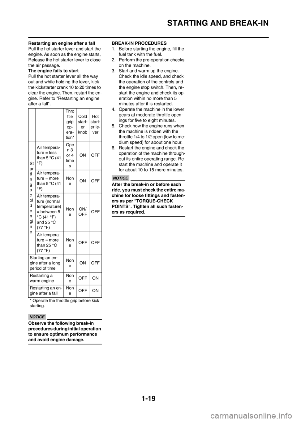
Restarting an engine after a fall
Pull the hot starter lever and start the
engine. As soon as the engine starts,
Release the hot starter lever to close
the air passage.
The engine fails to start
Pull the hot starter lever all the way
out and while holding the lever, kick
the kickstarter crank 10 to 20 times to
clear the engine. Then, restart the en-
gine. Refer to "Restarting an engine
after a fall".
Observe the following break-in
procedures during initial operation
to ensure optimum performance
and avoid engine damage.
BREAK-IN PROCEDURES
1. Before starting the engine, fill the
fuel tank with the fuel.
2. Perform the pre-operation checks
on the machine.
3. Start and warm up the engine.
Check the idle speed, and check
the operation of the controls and
the engine stop switch. Then, re-
start the engine and check its op-
eration within no more than 5
minutes after it is restarted.
4. Operate the machine in the lower
gears at moderate throttle open-
ings for five to eight minutes.
5. Check how the engine runs when
the machine is ridden with the
throttle 1/4 to 1/2 open (low to me-
dium speed) for about one hour.
6. Restart the engine and check the
operation of the machine through-
out its entire operating range. Re-
start the machine and operate it
for about 10 to 15 more minutes.
After the break-in or before each
ride, you must check the entire ma-
chine for loose fittings and fasten-
ers as per "TORQUE-CHECK
POINTS". Tighten all such fasten-
ers as required.
Thro
ttle
grip
op-
era-
tion*Cold
start-
er
knobHot
start-
er le-
ver
St
ar
ti
n
g
a
c
ol
d
e
n
gi
n
eAir tempera-
ture = less
than 5 °C (41
°F)Ope
n 3
or 4
time
sON OFF
Air tempera-
ture = more
than 5 °C (41
°F)Non
eON OFF
Air tempera-
ture (normal
temperature)
= between 5
°C (41 °F)
and 25 °C
(77 °F)Non
eON/
OFFOFF
Air tempera-
ture = more
than 25 °C
(77 °F)Non
eOFF OFF
Starting an en-
gine after a long
period of timeNon
eON OFF
Restarting a
warm engineNon
eOFF ON
Restarting an en-
gine after a fallNon
eOFF ON
* Operate the throttle grip before kick
starting.
Page 30 of 232
1-20
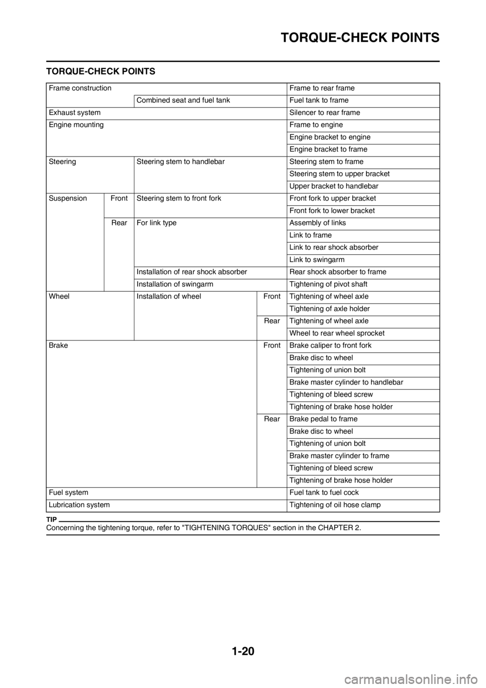
TORQUE-CHECK POINTS
TORQUE-CHECK POINTS
Concerning the tightening torque, refer to "TIGHTENING TORQUES" section in the CHAPTER 2.
Frame construction Frame to rear frame
Combined seat and fuel tank Fuel tank to frame
Exhaust system Silencer to rear frame
Engine mounting Frame to engine
Engine bracket to engine
Engine bracket to frame
Steering Steering stem to handlebar Steering stem to frame
Steering stem to upper bracket
Upper bracket to handlebar
Suspension Front Steering stem to front fork Front fork to upper bracket
Front fork to lower bracket
Rear For link type Assembly of links
Link to frame
Link to rear shock absorber
Link to swingarm
Installation of rear shock absorber Rear shock absorber to frame
Installation of swingarm Tightening of pivot shaft
Wheel Installation of wheel Front Tightening of wheel axle
Tightening of axle holder
Rear Tightening of wheel axle
Wheel to rear wheel sprocket
Brake Front Brake caliper to front fork
Brake disc to wheel
Tightening of union bolt
Brake master cylinder to handlebar
Tightening of bleed screw
Tightening of brake hose holder
Rear Brake pedal to frame
Brake disc to wheel
Tightening of union bolt
Brake master cylinder to frame
Tightening of bleed screw
Tightening of brake hose holder
Fuel system Fuel tank to fuel cock
Lubrication system Tightening of oil hose clamp
Page 43 of 232
2-12
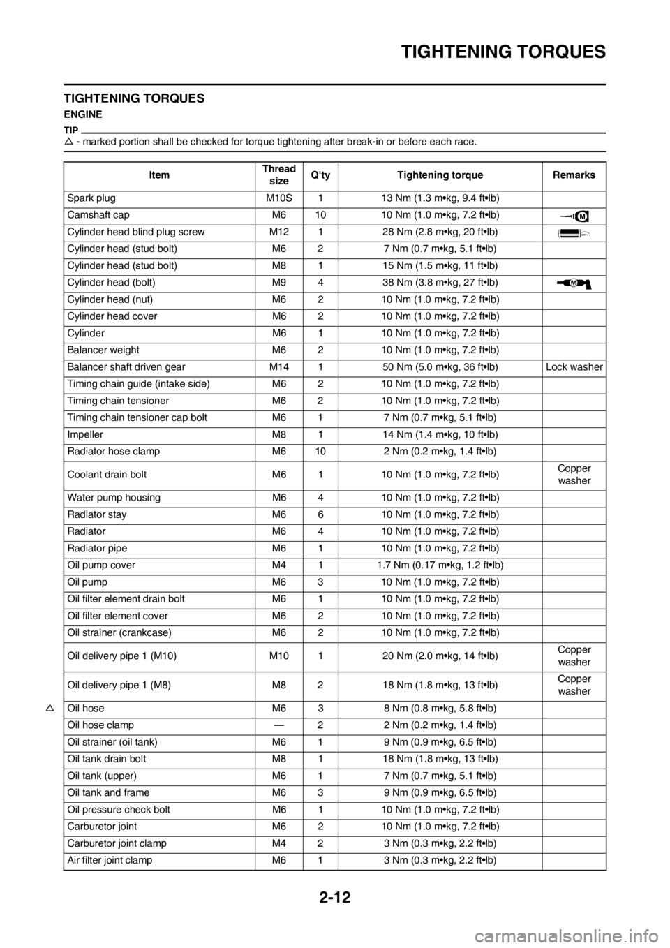
TIGHTENING TORQUES
TIGHTENING TORQUES
ENGINE
△- marked portion shall be checked for torque tightening after break-in or before each race.
ItemThread
sizeQ'ty Tightening torque Remarks
Spark plug M10S 1 13 Nm (1.3 m•kg, 9.4 ft•lb)
Camshaft cap M6 10 10 Nm (1.0 m•kg, 7.2 ft•lb)
Cylinder head blind plug screw M12 1 28 Nm (2.8 m•kg, 20 ft•lb)
Cylinder head (stud bolt) M6 2 7 Nm (0.7 m•kg, 5.1 ft•lb)
Cylinder head (stud bolt) M8 1 15 Nm (1.5 m•kg, 11 ft•lb)
Cylinder head (bolt) M9 4 38 Nm (3.8 m•kg, 27 ft•lb)
Cylinder head (nut) M6 2 10 Nm (1.0 m•kg, 7.2 ft•lb)
Cylinder head cover M6 2 10 Nm (1.0 m•kg, 7.2 ft•lb)
Cylinder M6 1 10 Nm (1.0 m•kg, 7.2 ft•lb)
Balancer weight M6 2 10 Nm (1.0 m•kg, 7.2 ft•lb)
Balancer shaft driven gear M14 1 50 Nm (5.0 m•kg, 36 ft•lb) Lock washer
Timing chain guide (intake side) M6 2 10 Nm (1.0 m•kg, 7.2 ft•lb)
Timing chain tensioner M6 2 10 Nm (1.0 m•kg, 7.2 ft•lb)
Timing chain tensioner cap bolt M6 1 7 Nm (0.7 m•kg, 5.1 ft•lb)
Impeller M8 1 14 Nm (1.4 m•kg, 10 ft•lb)
Radiator hose clamp M6 10 2 Nm (0.2 m•kg, 1.4 ft•lb)
Coolant drain bolt M6 1 10 Nm (1.0 m•kg, 7.2 ft•lb)Copper
washer
Water pump housing M6 4 10 Nm (1.0 m•kg, 7.2 ft•lb)
Radiator stay M6 6 10 Nm (1.0 m•kg, 7.2 ft•lb)
Radiator M6 4 10 Nm (1.0 m•kg, 7.2 ft•lb)
Radiator pipe M6 1 10 Nm (1.0 m•kg, 7.2 ft•lb)
Oil pump cover M4 1 1.7 Nm (0.17 m•kg, 1.2 ft•lb)
Oil pump M6 3 10 Nm (1.0 m•kg, 7.2 ft•lb)
Oil filter element drain bolt M6 1 10 Nm (1.0 m•kg, 7.2 ft•lb)
Oil filter element cover M6 2 10 Nm (1.0 m•kg, 7.2 ft•lb)
Oil strainer (crankcase) M6 2 10 Nm (1.0 m•kg, 7.2 ft•lb)
Oil delivery pipe 1 (M10) M10 1 20 Nm (2.0 m•kg, 14 ft•lb)Copper
washer
Oil delivery pipe 1 (M8) M8 2 18 Nm (1.8 m•kg, 13 ft•lb)Copper
washer
△Oil hose M6 3 8 Nm (0.8 m•kg, 5.8 ft•lb)
Oil hose clamp — 2 2 Nm (0.2 m•kg, 1.4 ft•lb)
Oil strainer (oil tank) M6 1 9 Nm (0.9 m•kg, 6.5 ft•lb)
Oil tank drain bolt M8 1 18 Nm (1.8 m•kg, 13 ft•lb)
Oil tank (upper) M6 1 7 Nm (0.7 m•kg, 5.1 ft•lb)
Oil tank and frame M6 3 9 Nm (0.9 m•kg, 6.5 ft•lb)
Oil pressure check bolt M6 1 10 Nm (1.0 m•kg, 7.2 ft•lb)
Carburetor joint M6 2 10 Nm (1.0 m•kg, 7.2 ft•lb)
Carburetor joint clamp M4 2 3 Nm (0.3 m•kg, 2.2 ft•lb)
Air filter joint clamp M6 1 3 Nm (0.3 m•kg, 2.2 ft•lb)
Page 60 of 232
3-1
PERIODIC MAINTENANCE CHART FOR THE EMISSIONCONTROL SYSTEM (For Canada)
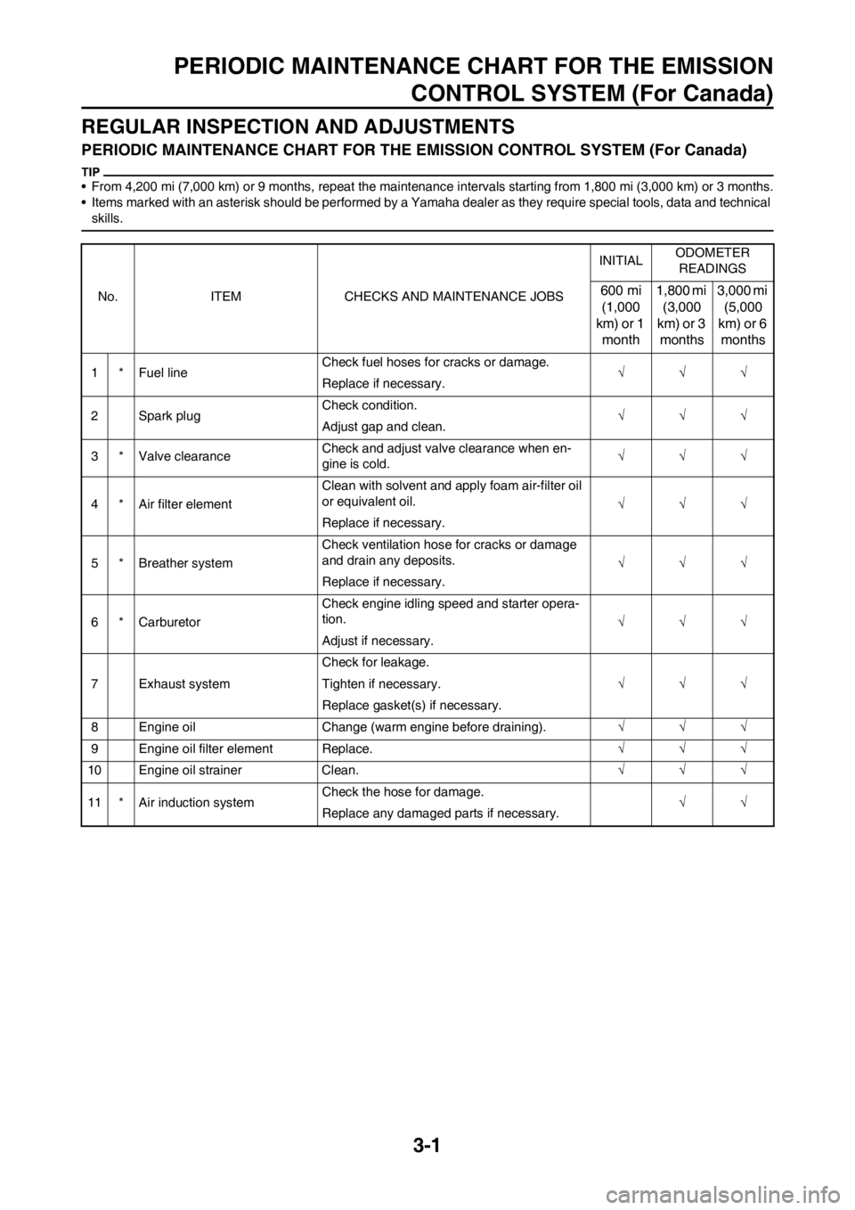
REGULAR INSPECTION AND ADJUSTMENTS
PERIODIC MAINTENANCE CHART FO R THE EMISSION CONTROL SYSTEM (For Canada)
• From 4,200 mi (7,000 km) or 9 months, repeat the maintenanc e intervals starting from 1,800 mi (3,000 km) or 3 months.
• Items marked with an asterisk should be performed by a Yam aha dealer as they require special tools, data and technical
skills.
No. ITEM CHECKS AND MAINTENANCE JOBS INITIAL
ODOMETER
READINGS600 mi (1,000
km) or 1 month 1,800 mi
(3,000
km) or 3 months 3,000 mi
(5,000
km) or 6 months
1 * Fuel line Check fuel hoses for cracks or damage.
Replace if necessary.
2 Spark plug Check condition.
Adjust gap and clean.
3 * Valve clearance Check and adjust valve clearance when en-
gine is cold.
4 * Air filter element Clean with solvent and apply foam air-filter oil
or equivalent oil.
Replace if necessary.
5 * Breather system Check ventilation hose for cracks or damage
and drain any deposits.
Replace if necessary.
6 * Carburetor Check engine idling speed and starter opera-
tion.
Adjust if necessary.
7 Exhaust system Check for leakage.
Tighten if necessary.
Replace gasket(s) if necessary.
8 Engine oil Change (warm engine before draining).
9 Engine oil filter element Replace.
10 Engine oil strainer Clean.
11 * Air induction system Check the hose for damage.
Replace any damaged parts if necessary.
Page 62 of 232
3-3
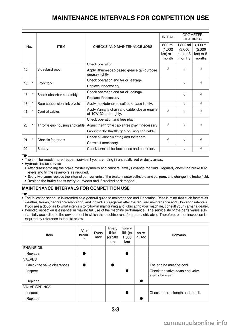
MAINTENANCE INTERVALS FOR COMPETITION USE
• The air filter needs more frequent service if you are riding in unusually wet or dusty areas.
• Hydraulic brake service
• After disassembling the brake master cylinders and calipers, always change the fluid. Regularly check the brake fluid
levels and fill the reservoirs as required.
• Every two years replace the internal components of the brake master cylinders and calipers, and change the brake fluid.
• Replace the brake hoses every four years and if cracked or damaged.
MAINTENANCE INTERVALS FOR COMPETITION USE
• The following schedule is intended as a general guide to maintenance and lubrication. Bear in mind that such factors as
weather, terrain, geographical location, and individual usage will alter the required maintenance and lubrication intervals.
If you are a doubt as to what intervals to follow in maintaining and lubricating your machine, consult your Yamaha dealer.
• Periodic inspection is essential in making full use of the machine performance. The service life of the parts varies sub-
stantially according to the environment in which the machine runs (e.g., rain, dirt, etc.). Therefore, earlier inspection is
required by reference to the list below.
15 Sidestand pivotCheck operation.
Apply lithium-soap-based grease (all-purpose
grease) lightly.
16 * Front forkCheck operation and for oil leakage.
Replace if necessary.
17 * Shock absorber assemblyCheck operation and for oil leakage.
Replace if necessary.
18 * Rear suspension link pivots Apply molybdenum disulfide grease lightly.
19 * Control cablesApply Yamaha chain and cable lube or engine
oil 10W-30 thoroughly.
20 * Throttle grip housing and cableCheck operation and free play.
Adjust the throttle cable free play if necessary.
Lubricate the throttle grip housing and cable.
21 * Chassis fastenersCheck all chassis fitting and fasteners.
Correct if necessary.
22 Battery Check terminal for looseness and corrosion. No. ITEM CHECKS AND MAINTENANCE JOBSINITIALODOMETER
READINGS
600 mi
(1,000
km) or 1
month1,800 mi
(3,000
km) or 3
months3,000 mi
(5,000
km) or 6
months
ItemAfter
break-
inEvery
race
Every
third
(or 500
km)Every
fifth (or
1,000
km)
As re-
quiredRemarks
ENGINE OIL
Replace●●
VALVES
Check the valve clearances●●The engine must be cold.
Inspect●Check the valve seats and valve
stems for wear.
Replace●
VALVE SPRINGS
Inspect●Check the free length and the tilt.
Replace●
Page 64 of 232

3-5
MAINTENANCE INTERVALS FOR COMPETITION USE
CRANK
Inspect and clean●●
CARBURETOR
Inspect, adjust and clean●●
AIR INDUCTION SYSTEM
Inspect and clean●● ●●
SPARK PLUG
Inspect and clean●●
Replace●
DRIVE CHAIN Use chain lube.
Lubricate, slack, alignment●●Chain slack: 48–58 mm (1.9–2.3 in)
Replace●
COOLING SYSTEM
Check coolant level and leakage●●
Check radiator cap operation●
Replace coolant●Every two years
Inspect hoses●
OUTSIDE NUTS AND BOLTS
Retighten●●Refer to "STARTING AND BREAK-
IN" section in the CHAPTER 1.
AIR FILTER
Clean and lubricate●●Use foam air-filter oil or equivalent oil.
Replace●
OIL FILTER
Replace●●
ENGINE GUARD
Replace●Breakage
FRAME
Clean and inspect●●
FUEL TANK, COCK
Clean and inspect●●
BRAKES
Adjust lever position and pedal
height●●
Lubricate pivot point●●
Check brake disc surface●●
Check fluid level and leakage●●
Retighten brake disc bolts, cali-
per bolts, master cylinder bolts
and union bolts●●
Replace pads●
Replace brake fluid●Every one year ItemAfter
break-
inEvery
race
Every
third
(or 500
km)Every
fifth (or
1,000
km)
As re-
quiredRemarks