gas type YAMAHA WR 250F 2016 Owners Manual
[x] Cancel search | Manufacturer: YAMAHA, Model Year: 2016, Model line: WR 250F, Model: YAMAHA WR 250F 2016Pages: 428, PDF Size: 14.13 MB
Page 44 of 428

STARTING AND BREAK-IN
1-30
EAS2GB7048
STARTING AND BREAK-IN
EAS2GB7049FUEL
Always use the recommended fuel as stated
below. Also, be sure to use new gasoline the
day of a race.
ECA
NOTICE
Use only unleaded gasoline. The use of
leaded gasoline will cause severe damage
to the engine internal parts such as valves,
piston rings, and exhaust system, etc.
TIP
Your Yamaha engine has been designed to use
premium unleaded gasoline with a pump oc-
tane number [(R+M)/2] of 91 or higher, or a re-
search octane number of 95 or higher. If
knocking (or pinging) occurs, use a gasoline of
a different brand.
EWA
WARNING
• For refueling, be sure to stop the engine
and use enough care not to spill any fuel.
Also be sure to avoid refueling close to a
fire.
• Refuel after the engine, exhaust pipe, etc.
have cooled off.
Gasohol (For USA and Canada)
There are two types of gasohol: gasohol con-
taining ethanol and that containing methanol.
Gasohol containing ethanol can be used if the
ethanol content does not exceed 10%. Gasohol
containing methanol is not recommended by
Yamaha because it can cause damage to the
fuel system or vehicle performance problems.
EAS2GB7050HANDLING NOTEEWA
WARNING
Never start or run the engine in a closed ar-
ea. The exhaust fumes are poisonous; they
can cause loss of consciousness and death
in a very short time. Always operate the ma-
chine in a well-ventilated area.
ECA
NOTICE
• Unlike a two-stroke engine, this engine
cannot be kick started when the throttle is
open because the kickstarter may kick
back. Also, if the throttle is open the air/
fuel mixture may be too lean for the engine
to start.
• Before starting the machine, perform the
checks in the pre-operation check list.
EAS2GB7051AIR FILTER MAINTENANCE
According to “CLEANING THE AIR FILTER
ELEMENT” section in the CHAPTER 3, apply
the foam-air-filter oil or its equivalent to the ele-
ment. (Excess oil in the element may adversely
affect engine starting.)
EAS2GB7052STARTING A COLD ENGINEECA
NOTICE
For maximum engine life, never accelerate
hard when the engine is cold!
In order for the ignition circuit cut-off system to
enable starting, one of the following conditions
must be met:
• The transmission is in the neutral position.
• The transmission is in gear with the clutch le-
ver pulled.
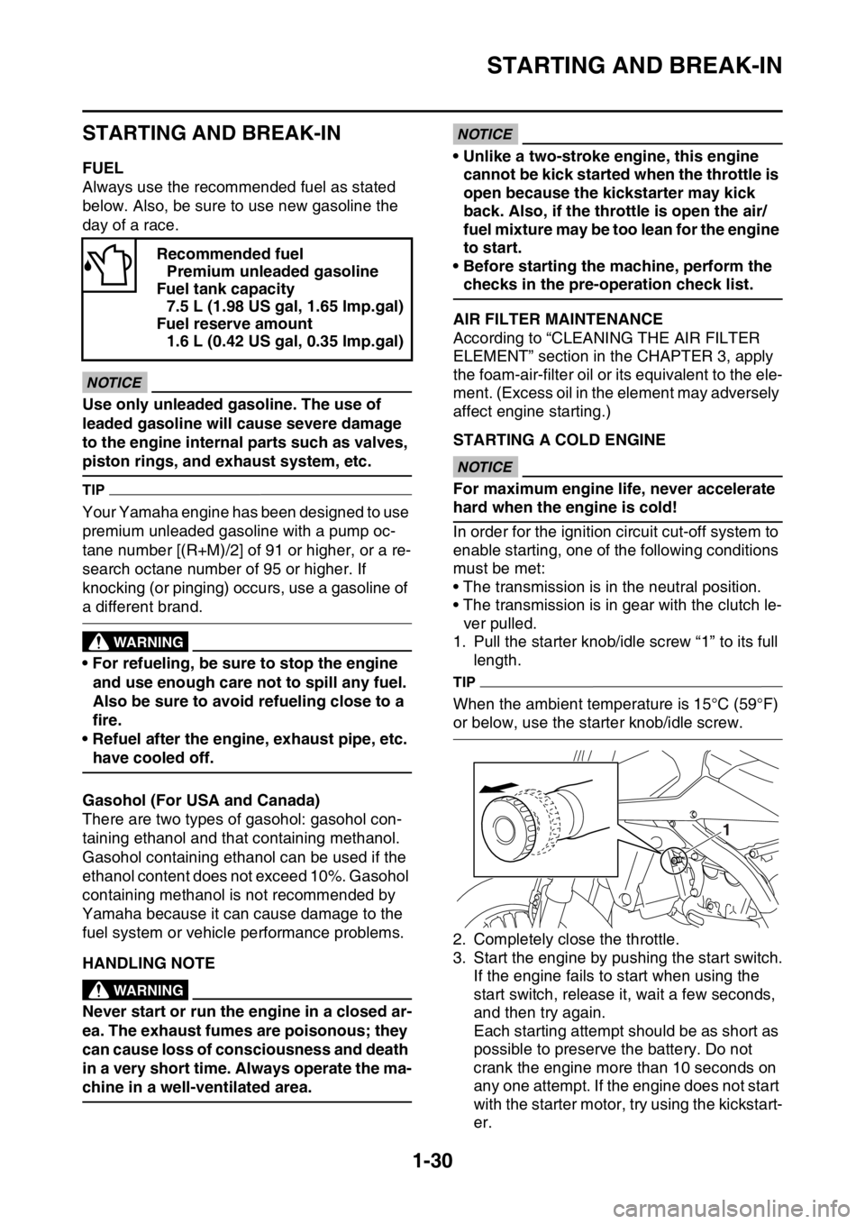
1. Pull the starter knob/idle screw “1” to its full
length.
TIP
When the ambient temperature is 15°C (59°F)
or below, use the starter knob/idle screw.
2. Completely close the throttle.
3. Start the engine by pushing the start switch.
If the engine fails to start when using the
start switch, release it, wait a few seconds,
and then try again.
Each starting attempt should be as short as
possible to preserve the battery. Do not
crank the engine more than 10 seconds on
any one attempt. If the engine does not start
with the starter motor, try using the kickstart-
er. Recommended fuel
Premium unleaded gasoline
Fuel tank capacity
7.5 L (1.98 US gal, 1.65 lmp.gal)
Fuel reserve amount
1.6 L (0.42 US gal, 0.35 lmp.gal)
1
Page 55 of 428

ENGINE SPECIFICATIONS
2-2
EAS2GB7062
ENGINE SPECIFICATIONS
Engine
Engine type Liquid cooled 4-stroke, DOHC
Displacement 250 cm
3
Cylinder arrangement Single cylinder
Bore stroke 77.0 53.6 mm (3.0 2.1 in)
Compression ratio 13.5:1
Starting system Electric starter and kickstarter
Fuel
Recommended fuel Premium unleaded gasoline only
Fuel tank capacity 7.5 L (1.98 US gal, 1.65 Imp.gal)
Fuel reserve amount 1.6 L (0.42 US gal, 0.35 Imp.gal)
Engine oil
Lubrication system Wet sump
Recommended brand YAMALUBE
Type SAE 10W-40, SAE 10W-50, SAE 15W-40,
SAE 20W-40 or SAE 20W-50
Recommended engine oil grade API service SG type or higher, JASO standard
MA
Engine oil quantity
Quantity (disassembled) 1.10 L (1.16 US qt, 0.97 Imp.qt)
Without oil filter element replacement 0.83 L (0.88 US qt, 0.73 Imp.qt)
With oil filter element replacement 0.85 L (0.90 US qt, 0.75 Imp.qt)
Oil filter
Oil filter type Paper
Bypass valve opening pressure 40.0–80.0 kPa (0.40–0.80 kgf/cm
2,
5.8–11.6 psi)
Oil pump
Oil pump type Trochoid
Inner-rotor-to-outer-rotor-tip clearance Less than 0.150 mm (0.0059 in)
Limit 0.20 mm (0.0079 in)
Outer-rotor-to-oil-pump-housing clearance 0.13–0.18 mm (0.0051–0.0071 in)
Limit 0.24 mm (0.0094 in)
Oil-pump-housing-to-inner-and-outer-rotor
clearance 0.06–0.11 mm (0.0024–0.0043 in)
Limit 0.17 mm (0.0067 in)
Cooling system
Radiator (including all routes) 1.00 L (1.06 US qt, 0.88 Imp.qt)
Radiator capacity 0.56 L (0.60 US qt, 0.50 Imp.qt)
Radiator cap valve opening pressure 107.9–137.3 kPa (1.08–1.37 kg/cm
2,
15.6–19.9 psi)
Radiator core
Width 112.6 mm (4.43 in)
Height 235.0 mm (9.25 in)
Depth 28.0 mm (1.10 in)
Water pump
Water pump type Single suction centrifugal pump
Spark plug(s)
Manufacturer/model NGK/LMAR8G
Spark plug gap 0.7–0.8 mm (0.028–0.031 in)
Page 62 of 428

CHASSIS SPECIFICATIONS
2-9
Rear suspension
Type Swingarm (link suspension)
Spring/shock absorber type Coil spring/gas-oil damper
Rear shock absorber assembly travel 126.0 mm (4.96 in)
Spring free length 275.0 mm (10.83 in)
Spring installed length 265.0 mm (10.43 in)
Spring rate K1 54.00 N/mm (5.51 kgf/mm, 308.34 lbf/in)
Spring stroke K1 0.0–150.0 mm (0.00–5.91 in)
Optional spring available Yes
Enclosed gas/air pressure (STD) 980 kPa (9.8 kgf/cm
2, 139.4 psi)
Spring preload adjusting positions
Minimum Position in which the spring is turned in 1.5 mm
(0.06 in) from its free length.
Standard Position in which the spring is turned in 10 mm
(0.39 in) from its free length.
Maximum Position in which the spring is turned in 18 mm
(0.71 in) from its free length.
Rebound damping adjusting positions
Minimum 30 clicks out*
Standard 14 clicks out*
Maximum Fully turned in
* With the adjuster fully turned in
Compression damping setting
(for fast compression damping)
Minimum 2 turns out*
Standard 1-1/4 turns out*
Maximum Fully turned in
* With the adjuster fully turned in
Compression damping setting
(for slow compression damping)
Minimum 20 clicks out*
Standard 10 clicks out*
Maximum Fully turned in
* With the adjuster fully turned in
Swingarm
Swingarm end free play limit (radial) 1.0 mm (0.04 in)
Swingarm end free play limit (axial) 0.2–0.9 mm (0.01–0.04 in)
Drive chain
Size/manufacturer 520VM2/DAIDO
Number of links 114
Drive chain slack 50–60 mm (1.97–2.36 in)
15-link length limit 239.3 mm (9.42 in)
Page 73 of 428

LUBRICATION POINTS AND LUBRICANT TYPES
2-20
EAS2GB7068
LUBRICATION POINTS AND LUBRICANT TYPES
EAS2GB7069ENGINE
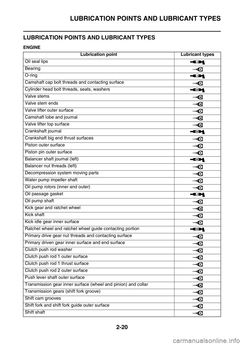
Lubrication point Lubricant types
Oil seal lips
Bearing
O-ring
Camshaft cap bolt threads and contacting surface
Cylinder head bolt threads, seats, washers
Valve stems
Valve stem ends
Valve lifter outer surface
Camshaft lobe and journal
Valve lifter top surface
Crankshaft journal
Crankshaft big end thrust surfaces
Piston outer surface
Piston pin outer surface
Balancer shaft journal (left)
Balancer nut threads (left)
Decompression system moving parts
Water pump impeller shaft
Oil pump rotors (inner and outer)
Oil passage gasket
Oil pump shaft
Kick gear and ratchet wheel
Kick shaft
Kick idle gear inner surface
Ratchet wheel and ratchet wheel guide contacting portion
Primary drive gear nut threads and contacting surface
Primary driven gear inner surface and end surface
Clutch push rod washer
Clutch push rod 1 outer surface
Clutch push rod 1 thrust surface
Clutch push rod 2 outer surface
Push lever shaft outer surface
Transmission gear inner surface (wheel and pinion) and collar
Transmission gears (shift fork groove)
Shift cam grooves
Shift fork and shift fork guide outer surface
Shift shaft
LS
E
LS
E
M
M
M
E
M
M
M
E
E
E
M
E
E
E
E
LS
E
M
E
E
M
E
E
E
E
E
E
E
M
E
E
E
E
Page 74 of 428

LUBRICATION POINTS AND LUBRICANT TYPES
2-21
EAS2GB7070CHASSISShift lever assembly moving parts
Damper assembly shaft, thrust surfaces, washers
Starter idle gear inner surface, thrust surfaces
Starter clutch drive gear inner surface, thrust surfaces
Cylinder head cover gasketThree bond
No.1215®
Crankcase mating surfaceThree bond
No.1215®
Stator assembly lead grommetThree bond
No.1215®
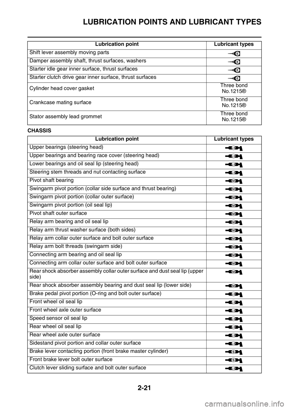
Lubrication point Lubricant types
Upper bearings (steering head)
Upper bearings and bearing race cover (steering head)
Lower bearings and oil seal lip (steering head)
Steering stem threads and nut contacting surface
Pivot shaft bearing
Swingarm pivot portion (collar side surface and thrust bearing)
Swingarm pivot portion (collar outer surface)
Swingarm pivot portion (oil seal lip)
Pivot shaft outer surface
Relay arm bearing and oil seal lip
Relay arm thrust washer surface (both sides)
Relay arm collar outer surface and bolt outer surface
Relay arm bolt threads (swingarm side)
Connecting arm bearing and oil seal lip
Connecting arm collar outer surface and bolt outer surface
Rear shock absorber assembly collar outer surface and dust seal lip (upper
side)
Rear shock absorber assembly bearing and dust seal lip (lower side)
Brake pedal pivot portion (O-ring and bolt outer surface)
Front wheel oil seal lip
Front wheel axle outer surface
Speed sensor oil seal lip
Rear wheel oil seal lip
Rear wheel axle outer surface
Sidestand pivot portion and collar outer surface
Brake lever contacting portion (front brake master cylinder)
Front brake lever bolt outer surface
Clutch lever sliding surface and bolt outer surfaceLubrication point Lubricant types
E
E
E
E
LS
LS
LS
LS
M
M
M
M
M
M
M
M
M
M
M
M
M
LS
LS
LS
LS
LS
LS
LS
S
S
LS
Page 139 of 428

ELECTRICAL SYSTEM
3-39
EAS2GB7130
ELECTRICAL SYSTEM
EAS2GB7131CHECKING THE SPARK PLUG
1. Remove:
• Seat
• Air scoop (left/right)
Refer to “GENERAL CHASSIS” on page 5-
1.
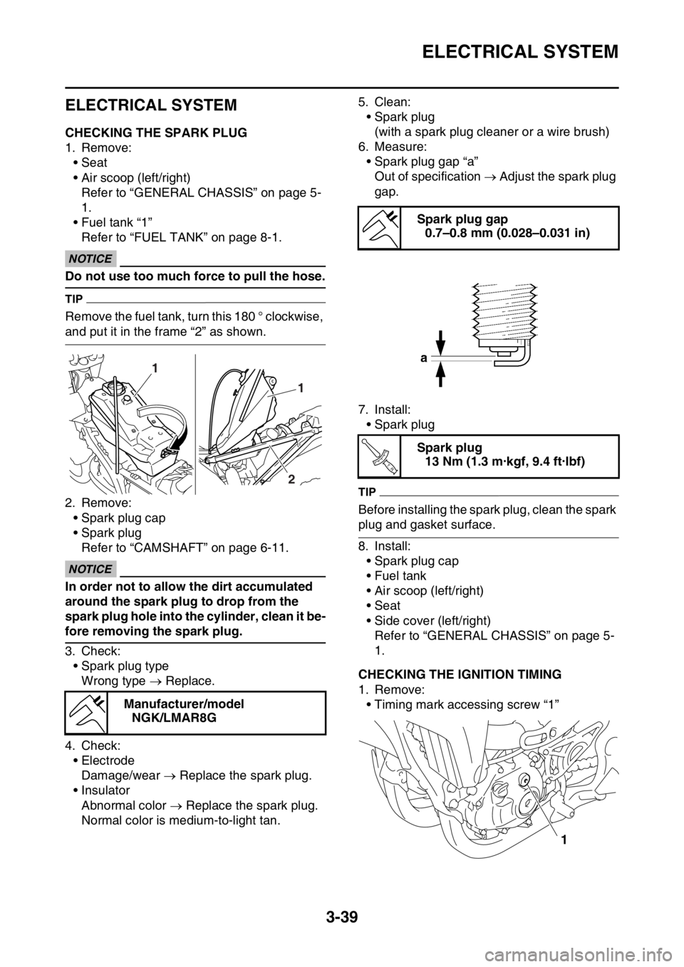
• Fuel tank “1”
Refer to “FUEL TANK” on page 8-1.
ECA
NOTICE
Do not use too much force to pull the hose.
TIP
Remove the fuel tank, turn this 180 ° clockwise,
and put it in the frame “2” as shown.
2. Remove:
• Spark plug cap
• Spark plug
Refer to “CAMSHAFT” on page 6-11.
ECA
NOTICE
In order not to allow the dirt accumulated
around the spark plug to drop from the
spark plug hole into the cylinder, clean it be-
fore removing the spark plug.
3. Check:
• Spark plug type
Wrong type Replace.
4. Check:
• Electrode
Damage/wear Replace the spark plug.
• Insulator
Abnormal color Replace the spark plug.
Normal color is medium-to-light tan.5. Clean:
• Spark plug
(with a spark plug cleaner or a wire brush)
6. Measure:
• Spark plug gap “a”
Out of specification Adjust the spark plug
gap.
7. Install:
• Spark plug
TIP
Before installing the spark plug, clean the spark
plug and gasket surface.
8. Install:
• Spark plug cap
• Fuel tank
• Air scoop (left/right)
• Seat
• Side cover (left/right)
Refer to “GENERAL CHASSIS” on page 5-
1.
EAS2GB7132CHECKING THE IGNITION TIMING
1. Remove:
• Timing mark accessing screw “1” Manufacturer/model
NGK/LMAR8G
1
1
2
Spark plug gap
0.7–0.8 mm (0.028–0.031 in)
Spark plug
13 Nm (1.3 m·kgf, 9.4 ft·lbf)
T R..
1