ad blue YAMAHA WR 250F 2017 Owners Manual
[x] Cancel search | Manufacturer: YAMAHA, Model Year: 2017, Model line: WR 250F, Model: YAMAHA WR 250F 2017Pages: 432, PDF Size: 14.14 MB
Page 85 of 432

CABLE ROUTING DIAGRAM
2-32
1. Clutch cable
2. Throttle cable (return)
3. Throttle cable (pull)
4. Engine stop switch lead
5. Coupler for connecting optional part
6. Engine stop switch coupler
7. Rectifier/regulator coupler
8. AC magneto lead
9. Starter knob/idle screw
10. Starter motor lead
11. Radiator fan fuse
12. Taillight lead
13. Headlight relay (yellow tape)
14. Starting circuit cut-off relay (no identification
tape)
15. Diode
16. Holder plate
17. Left of the vehicle:radiator fan motor relay (blue
tape)
Right of the vehicle:main relay (red tape)
18. Neutral switch lead
19. Engine bracket
20. Front engine bracket
21. Plastic locking tie
22. Radiator hose
23. Neutral switch coupler
24. Crankshaft position sensor coupler
25. Tension arm
26. Wire harness
27. Tank rail
28. Rectifier/regulator
29. Rectifier/regulator bracket
30. Rear frame
31. Side cover 5
32. Crankcase cover
33. Crankcase
34. Lead holder
35. Frame
A. Pass the engine stop switch lead between the
frame and the cable holder.
B. Insert the coupler for connecting optional part into
the connector, and fix it to the bracket.
C. Insert and fix the engine stop switch coupler to
the bracket.
D. Insert and fix the rectifier/regulator coupler to the
bracket.
E. Pass the AC magneto lead to the front of the ve-
hicle beyond the starter knob/idle screw and to
the rear of the vehicle beyond the radiator. No
pinch is allowed between the radiator and the
tension arm.
F. Place the rear grommet of the starter motor lead
matching the rear end of the side cover.
G. Insert the radiator fan motor fuse into the protru-
sion of the holder plate.
H. Place the diode on top of the rear fender on the
inner side of the rear frame.
I. Bring the neutral switch lead into line with the
crankcase cover with no sag allowed.
J. Route the AC magneto lead under the starter
clutch cover.
K. Pass the neutral switch lead to the inside of the
front engine bracket (the side of the vehicle).
L. Insert the plastic locking tie into the bracket hole
and clamp the clutch cable. Clamp it so that the
lock of the plastic locking tie faces downward,
and then cut off the end of the plastic locking tie.
M. Pass the clutch cable with no downward sag al-
lowed.N. Place the grommet of the clutch cable so that it
contacts the radiator hose. Route the clutch cable
outside the neutral switch lead, AC magneto lead
and starter motor lead.
O. Route each lead so that the leads are not pinched
between the radiator hose and the frame.
P. 40 mm (1.57 in)
Q. Clamp the clutch cable, AC magneto lead, neu-
tral switch lead and starter motor lead by the plas-
tic locking tie. Make sure that they are clamped at
the positioning tapes in the clutch cable and the
starter motor lead. Make the lock on the plastic
locking tie face the front of the vehicle, and cut
the end.
R. Clamp the starter motor lead to the inside of the
tension arm with a plastic locking tie. Clamp it so
that the lock of the plastic locking tie faces up-
ward and outward, and do not cut off the end of
the plastic locking tie. Route the lead so that there
is no slack at the bottom from the clamp position
onwards.
S. After connecting the neutral switch coupler, at-
tach the coupler cover.
T. After connecting the crankshaft position sensor
coupler, attach the coupler cover.
U. Pass the rectifier/regulator lead to the inside of
the tension arm (the side of the vehicle).
V. Pass the main harness to the front of the radiator
hose (the front of the vehicle), and to the inside of
the clutch cable (the side of the vehicle).
W. Pass the engine stop switch lead between the
coupler for connecting optional part and the tank
rail, with the lead on the main harness side facing
the top of the vehicle.
X. Insert the starter motor lead completely into the
end of the side cover 5.
Y. Clamp the clutch cable at the front of the lead (the
front of the vehicle).
Z. Insert the clip of the plastic locking tie into the
frame. Face the lock of the plastic locking tie for-
ward, and then cut off the end.
Page 91 of 432

CABLE ROUTING DIAGRAM
2-38
1. Battery negative lead
2. Fuel hose
3. Fuel pump coupler
4. Fuel pump lead
5. Resistor
6. Resistor coupler
7. Battery positive lead
8. Lean angle sensor
9. Starter motor lead
10. Radiator fan motor relay (blue tape)
11. Main relay (red tape)
12. Wire harness
13. Ground lead coupler
14. Starter relay coupler
15. Starter relay
16. Cross member
17. Diode
18. Taillight lead
19. Clamp
20. Fuel tank
21. Damper
22. Rear frame
23. Side cover 6
24. Plastic locking tie
A. After connecting the fuel pump coupler, attach
the coupler cover.
B. Pass the fuel hose to the front of the battery.
C. Route the resistor lead to the outside of the leads.
D. Connect the battery positive lead to the starter re-
lay terminal (in the left side of the vehicle).
E. Insert the protruding end of the wire harness into
the battery bracket hole and holder plate hole.
F. After connecting the negative lead coupler, place
it on the right side of the battery.
G. After installing the plastic cover to the starter re-
lay, connect the starter relay coupler.
H. Route the diode under the cross member and
place it on top of the rear fender.
I. Secure the two ends of the taillight coupler with
the starter motor lead.
J. Route the taillight lead so that it does not slack at
the rear of the vehicle.
K. Clamp the taillight lead and insert the clip into the
rear fender. Clamp it so that the lock faces in-
ward, and then cut off the excess end.
L. Route the battery positive lead under the cross
member.
M. Lower end of the rear frame
N. Clamp it so that the lock of the plastic locking tie
faces downward, insert the end into the rear
frame and side cover 6, and then cut off the ex-
cess end. After cutting off the excess end, make
sure that the plastic locking tie does not protrude
from the lower end of the rear frame.
O. Clamp it so that the lock of the plastic locking tie
faces downward, and then pass the end between
the fuel hose and rear frame.
P. Clamp the wire harness at the position of the
white tape.
Page 95 of 432

CABLE ROUTING DIAGRAM
2-42
1. Breather hose 3 (air filter breather hose)
2. Breather hose 1 (cylinder head breather hose)
3. Breather hose 2 (crankcase breather hose)
4. Joint pipe
A. Pass the breather hose 3 to the outside the throt-
tle cable.
B. Install the two breather hoses so that the yellow
paint mark is pointing forwards.
C. Align the white paint mark to the protruding por-
tion of the pipe to install breather hose 3.
D. Protruding portion of the pipe
E. Align the end with the paint mark of the breather
hose 3 to the end of the clip to install the clip.
F. Align with the blue paint mark and protruding por-
tion of the joint pipe to install the breather hose.
G. Install the clip as shown.
Page 147 of 432
CHASSIS
4-4
TIP
• If the machine is new and after it is broken in,
the same set length of the spring may change
because of the initial fatigue, etc. of the
spring. Therefore, be sure to make reevalua-
tion.
• If the standard figure cannot be achieved by
adjusting the adjuster and changing the set
length, replace the spring with an optional one
and make readjustment.
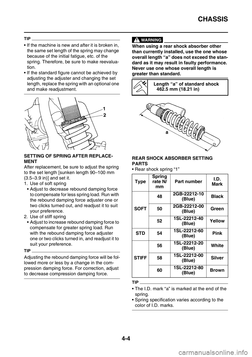
EAS2GBB146SETTING OF SPRING AFTER REPLACE-
MENT
After replacement, be sure to adjust the spring
to the set length [sunken length 90–100 mm
(3.5–3.9 in)] and set it.
1. Use of soft spring
• Adjust to decrease rebound damping force
to compensate for less spring load. Run with
the rebound damping force adjuster one or
two clicks turned out, and readjust it to suit
your preference.
2. Use of stiff spring
• Adjust to increase rebound damping force to
compensate for greater spring load. Run
with the rebound damping force adjuster
one or two clicks turned in, and readjust it to
suit your preference.
TIP
Adjusting the rebound damping force will be fol-
lowed more or less by a change in the com-
pression damping force. For correction, adjust
to decrease compression damping force.
EWA
WARNING
When using a rear shock absorber other
than currently installed, use the one whose
overall length “a” does not exceed the stan-
dard as it may result in faulty performance.
Never use one whose overall length is
greater than standard.
EAS2GBB147REAR SHOCK ABSORBER SETTING
PARTS
• Rear shock spring “1”
TIP
• The I.D. mark “a” is marked at the end of the
spring.
• Spring specification varies according to the
color of I.D. marks.
Length “a” of standard shock
462.5 mm (18.21 in)
TypeSpring
rate N/
mmPart numberI.D.
Mark
SOFT482GB-22212-10
(Blue)Black
502GB-22212-00
(Blue)Green
521SL-22212-40
(Blue)Yellow
STD 541SL-22212-60
(Blue)Pink
STIFF561SL-22212-20
(Blue)White
581SL-22212-00
(Blue)Silver
601SL-22212-80
(Blue)Brown
Page 244 of 432
CAMSHAFT
6-15
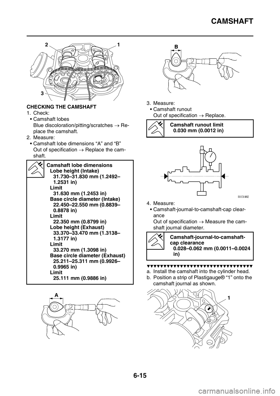
EAS2GBB239CHECKING THE CAMSHAFT
1. Check:
• Camshaft lobes
Blue discoloration/pitting/scratches Re-
place the camshaft.
2. Measure:
• Camshaft lobe dimensions “A” and “B”
Out of specification Replace the cam-
shaft.3. Measure:
• Camshaft runout
Out of specification Replace.
4. Measure:
• Camshaft-journal-to-camshaft-cap clear-
ance
Out of specification Measure the cam-
shaft journal diameter.
▼▼▼▼▼▼▼▼▼▼▼▼▼▼▼▼▼▼▼▼▼▼▼▼▼▼▼▼▼▼▼▼
a. Install the camshaft into the cylinder head.
b. Position a strip of Plastigauge® “1” onto the
camshaft journal as shown. Camshaft lobe dimensions
Lobe height (Intake)
31.730–31.830 mm (1.2492–
1.2531 in)
Limit
31.630 mm (1.2453 in)
Base circle diameter (Intake)
22.450–22.550 mm (0.8839–
0.8878 in)
Limit
22.350 mm (0.8799 in)
Lobe height (Exhaust)
33.370–33.470 mm (1.3138–
1.3177 in)
Limit
33.270 mm (1.3098 in)
Base circle diameter (Exhaust)
25.211–25.311 mm (0.9926–
0.9965 in)
Limit
25.111 mm (0.9886 in)
1
2
3
Camshaft runout limit
0.030 mm (0.0012 in)
Camshaft-journal-to-camshaft-
cap clearance
0.028–0.062 mm (0.0011–0.0024
in)
1
Page 257 of 432
VALVES AND VALVE SPRINGS
6-28
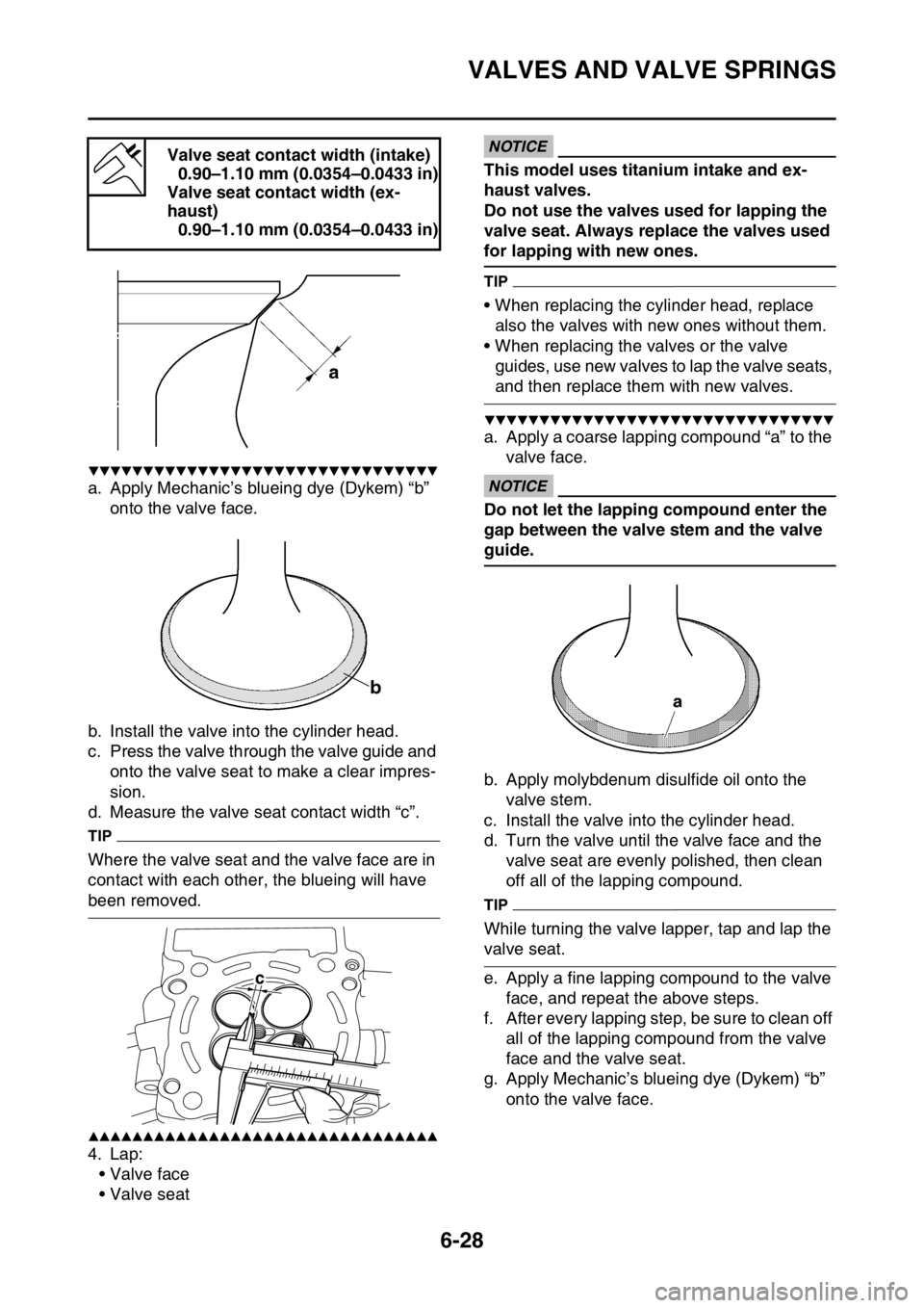
▼▼▼▼▼▼▼▼▼▼▼▼▼▼▼▼▼▼▼▼▼▼▼▼▼▼▼▼▼▼▼▼
a. Apply Mechanic’s blueing dye (Dykem) “b”
onto the valve face.
b. Install the valve into the cylinder head.
c. Press the valve through the valve guide and
onto the valve seat to make a clear impres-
sion.
d. Measure the valve seat contact width “c”.
TIP
Where the valve seat and the valve face are in
contact with each other, the blueing will have
been removed.
▲▲▲▲▲▲▲▲▲▲▲▲▲▲▲▲▲▲▲▲▲▲▲▲▲▲▲▲▲▲▲▲
4. Lap:
• Valve face
• Valve seat
ECA
NOTICE
This model uses titanium intake and ex-
haust valves.
Do not use the valves used for lapping the
valve seat. Always replace the valves used
for lapping with new ones.
TIP
• When replacing the cylinder head, replace
also the valves with new ones without them.
• When replacing the valves or the valve
guides, use new valves to lap the valve seats,
and then replace them with new valves.
▼▼▼▼▼▼▼▼▼▼▼▼▼▼▼▼▼▼▼▼▼▼▼▼▼▼▼▼▼▼▼▼
a. Apply a coarse lapping compound “a” to the
valve face.
ECA
NOTICE
Do not let the lapping compound enter the
gap between the valve stem and the valve
guide.
b. Apply molybdenum disulfide oil onto the
valve stem.
c. Install the valve into the cylinder head.
d. Turn the valve until the valve face and the
valve seat are evenly polished, then clean
off all of the lapping compound.
TIP
While turning the valve lapper, tap and lap the
valve seat.
e. Apply a fine lapping compound to the valve
face, and repeat the above steps.
f. After every lapping step, be sure to clean off
all of the lapping compound from the valve
face and the valve seat.
g. Apply Mechanic’s blueing dye (Dykem) “b”
onto the valve face. Valve seat contact width (intake)
0.90–1.10 mm (0.0354–0.0433 in)
Valve seat contact width (ex-
haust)
0.90–1.10 mm (0.0354–0.0433 in)
c
Page 264 of 432
CYLINDER AND PISTON
6-35
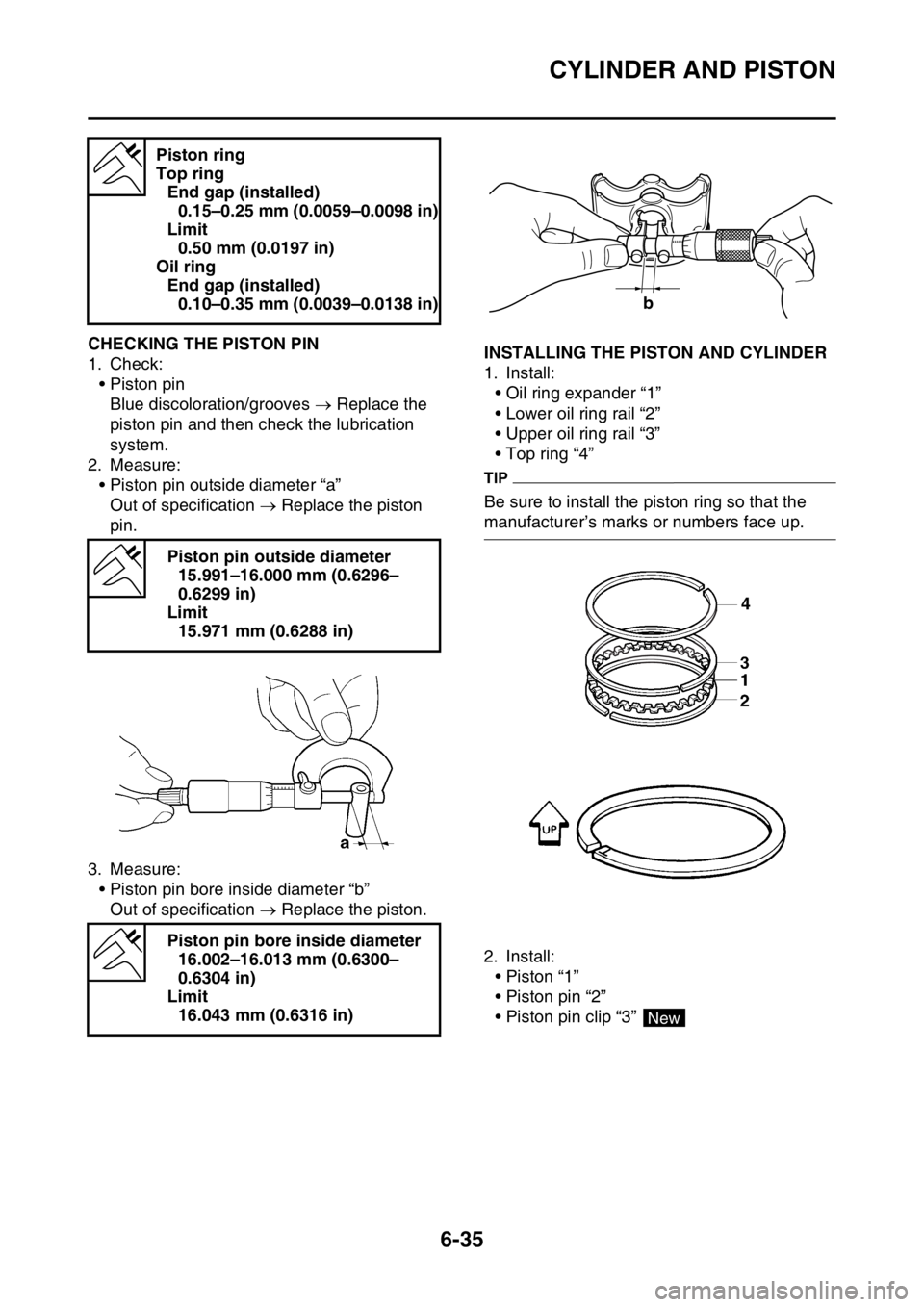
EAS2GBB260CHECKING THE PISTON PIN
1. Check:
• Piston pin
Blue discoloration/grooves Replace the
piston pin and then check the lubrication
system.
2. Measure:
• Piston pin outside diameter “a”
Out of specification Replace the piston
pin.
3. Measure:
• Piston pin bore inside diameter “b”
Out of specification Replace the piston.EAS2GBB261INSTALLING THE PISTON AND CYLINDER
1. Install:
• Oil ring expander “1”
• Lower oil ring rail “2”
• Upper oil ring rail “3”
• Top ring “4”
TIP
Be sure to install the piston ring so that the
manufacturer’s marks or numbers face up.
2. Install:
• Piston “1”
• Piston pin “2”
• Piston pin clip “3” Piston ring
Top ring
End gap (installed)
0.15–0.25 mm (0.0059–0.0098 in)
Limit
0.50 mm (0.0197 in)
Oil ring
End gap (installed)
0.10–0.35 mm (0.0039–0.0138 in)
Piston pin outside diameter
15.991–16.000 mm (0.6296–
0.6299 in)
Limit
15.971 mm (0.6288 in)
Piston pin bore inside diameter
16.002–16.013 mm (0.6300–
0.6304 in)
Limit
16.043 mm (0.6316 in)
b
4
New
Page 312 of 432
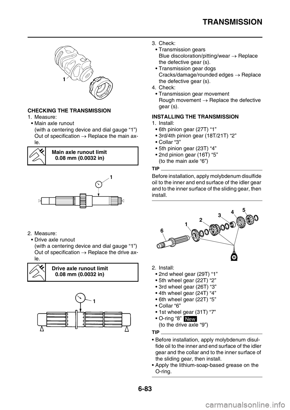
TRANSMISSION
6-83
EAS2GBB326CHECKING THE TRANSMISSION
1. Measure:
• Main axle runout
(with a centering device and dial gauge “1”)
Out of specification Replace the main ax-
le.
2. Measure:
• Drive axle runout
(with a centering device and dial gauge “1”)
Out of specification Replace the drive ax-
le.3. Check:
• Transmission gears
Blue discoloration/pitting/wear Replace
the defective gear (s).
• Transmission gear dogs
Cracks/damage/rounded edges Replace
the defective gear (s).
4. Check:
• Transmission gear movement
Rough movement Replace the defective
gear (s).EAS2GBB327INSTALLING THE TRANSMISSION
1. Install:
• 6th pinion gear (27T) “1”
• 3rd/4th pinion gear (18T/21T) “2”
• Collar “3”
• 5th pinion gear (23T) “4”
• 2nd pinion gear (16T) “5”
(to the main axle “6”)
TIP
Before installation, apply molybdenum disulfide
oil to the inner and end surface of the idler gear
and to the inner surface of the sliding gear, then
install.
2. Install:
• 2nd wheel gear (29T) “1”
• 5th wheel gear (22T) “2”
• 3rd wheel gear (26T) “3”
• 4th wheel gear (24T) “4”
• 6th wheel gear (22T) “5”
• Collar “6”
• 1st wheel gear (31T) “7”
• O-ring “8”
(to the drive axle “9”)
TIP
• Before installation, apply molybdenum disul-
fide oil to the inner and end surface of the idler
gear and the collar and to the inner surface of
the sliding gear, then install.
• Apply the lithium-soap-based grease on the
O-ring. Main axle runout limit
0.08 mm (0.0032 in)
Drive axle runout limit
0.08 mm (0.0032 in)
34
2
1
6
5
M
New
Page 372 of 432

FUEL INJECTION SYSTEM
9-36
2 Connection of wire harness
ECU coupler.
Check the locking condition
of the coupler.
Disconnect the coupler and
check the pins (bent or bro-
ken terminals and locking
condition of the pins).Improperly connected
Connect the coupler securely
or repair/replace the wire har-
ness.Crank the engine.
Fault code number is not dis-
played Service is finished.
Fault code number is dis-
played Go to item 3.
3 Wire harness continuity. Open or short circuit Re-
place the wire harness.
Between the crankshaft posi-
tion sensor coupler and ECU
coupler.
black/blue–black/blue
gray–grayCrank the engine.
Fault code number is not dis-
played Service is finished.
Fault code number is dis-
played Go to item 4.
4 Installed condition of crank-
shaft position sensor.
Check for looseness or
pinching.
Check the gap between the
crankshaft position sensor
and the pickup rotor.Improperly installed sensor
Reinstall or replace the
sensor.
Refer to “GENERATOR AND
STARTER CLUTCH” on
page 6-66.Crank the engine.
Fault code number is not dis-
played Service is finished.
Fault code number is dis-
played Go to item 5.
5 Defective crankshaft position
sensor.Check the crankshaft position
sensor.
Refer to “CHECKING THE
CRANKSHAFT POSITION
SENSOR” on page 9-75.Crank the engine.
Fault code number is not dis-
played Service is finished.
Fault code number is dis-
played Go to item 6.
6 Malfunction in ECU. Replace the ECU. Fault code No. 12
ItemCrankshaft position sensor: no normal signals are received
from the crankshaft position sensor.
Page 373 of 432

FUEL INJECTION SYSTEM
9-37
TIP
• If fault code numbers 13 and 14 are both displayed, perform the checks and maintenance jobs for
fault code number 13 first.
• Before troubleshooting, disconnect the starter motor lead from the starter relay.
Fault code No. 13
Item Intake air pressure sensor: open or short circuit detected.
Fail-safe systemAble to start engine
Able to drive vehicle
Diagnostic code No.03
Diagnostic tool displayDisplays the intake air pressure.
ProcedureOperate the throttle while pushing the start switch.(If the display
value changes, the performance is OK.)
ItemProbable cause of malfunc-
tion and checkMaintenance jobConfirmation of service
completion
1 Connection of intake air pres-
sure sensor coupler.
Check the locking condition
of the coupler.
Disconnect the coupler and
check the pins (bent or bro-
ken terminals and locking
condition of the pins).Improperly connected
Connect the coupler securely
or repair/replace the wire har-
ness.Push the start switch.
Fault code number is not dis-
played Service is finished.
Fault code number is dis-
played Go to item 2.
2 Connection of wire harness
ECU coupler.
Check the locking condition
of the coupler.
Disconnect the coupler and
check the pins (bent or bro-
ken terminals and locking
condition of the pins).Improperly connected
Connect the coupler securely
or repair/replace the wire har-
ness.Push the start switch.
Fault code number is not dis-
played Service is finished.
Fault code number is dis-
played Go to item 3.
3 Wire harness continuity. Open or short circuit Re-
place the wire harness.
Between intake air pressure
sensor coupler and ECU cou-
pler.
black/blue–black/blue
pink–pink
blue–bluePush the start switch.
Fault code number is not dis-
played Service is finished.
Fault code number is dis-
played Go to item 4.
4 Installed condition of intake
air pressure sensor.
Check for looseness or
pinching.Improperly installed sensor
Reinstall or replace the
sensor.Push the start switch.
Fault code number is not dis-
played Service is finished.
Fault code number is dis-
played Go to item 5.