diagram YAMAHA WR 250F 2017 Owners Manual
[x] Cancel search | Manufacturer: YAMAHA, Model Year: 2017, Model line: WR 250F, Model: YAMAHA WR 250F 2017Pages: 432, PDF Size: 14.14 MB
Page 8 of 432
EAS2GBB006
HOW TO USE THIS MANUAL
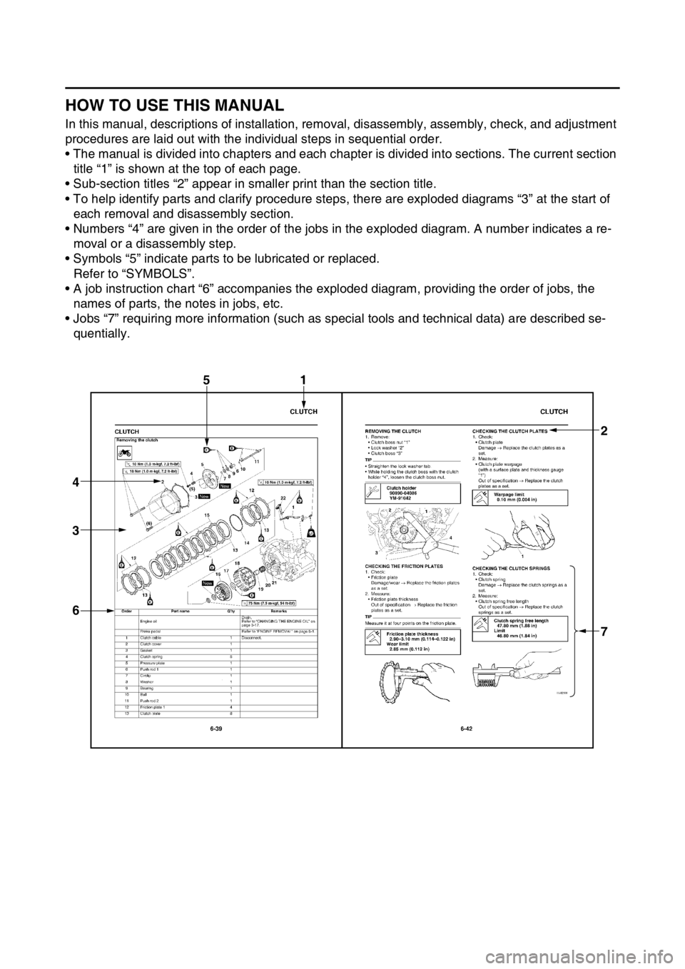
In this manual, descriptions of installation, removal, disassembly, assembly, check, and adjustment
procedures are laid out with the individual steps in sequential order.
• The manual is divided into chapters and each chapter is divided into sections. The current section
title “1” is shown at the top of each page.
• Sub-section titles “2” appear in smaller print than the section title.
• To help identify parts and clarify procedure steps, there are exploded diagrams “3” at the start of
each removal and disassembly section.
• Numbers “4” are given in the order of the jobs in the exploded diagram. A number indicates a re-
moval or a disassembly step.
• Symbols “5” indicate parts to be lubricated or replaced.
Refer to “SYMBOLS”.
• A job instruction chart “6” accompanies the exploded diagram, providing the order of jobs, the
names of parts, the notes in jobs, etc.
• Jobs “7” requiring more information (such as special tools and technical data) are described se-
quentially.
1
7 3 4
6
2
5
Page 14 of 432

MULTI-FUNCTION DISPLAY......................................................................... 1-22
DESCRIPTION ......................................................................................... 1-22
BASIC MODE ........................................................................................... 1-22
CHANGEOVER TO BASIC MODE/RACE MODE.................................... 1-23
RACE MODE ............................................................................................ 1-24
FUNCTION DIAGRAM ............................................................................. 1-28
STARTING AND BREAK-IN.......................................................................... 1-30
FUEL ........................................................................................................ 1-30
HANDLING NOTE .................................................................................... 1-30
AIR FILTER MAINTENANCE ................................................................... 1-30
STARTING A COLD ENGINE .................................................................. 1-30
STARTING A WARM ENGINE ................................................................. 1-32
BREAK-IN PROCEDURES ...................................................................... 1-32
MAINTENANCE AFTER BREAK-IN.............................................................. 1-33
MAJOR MAINTENANCE .......................................................................... 1-33
TORQUE-CHECK POINTS............................................................................ 1-34
MOTORCYCLE CARE AND STORAGE........................................................ 1-36
CARE........................................................................................................ 1-36
STORAGE ................................................................................................ 1-37
Page 42 of 432
MULTI-FUNCTION DISPLAY
1-28
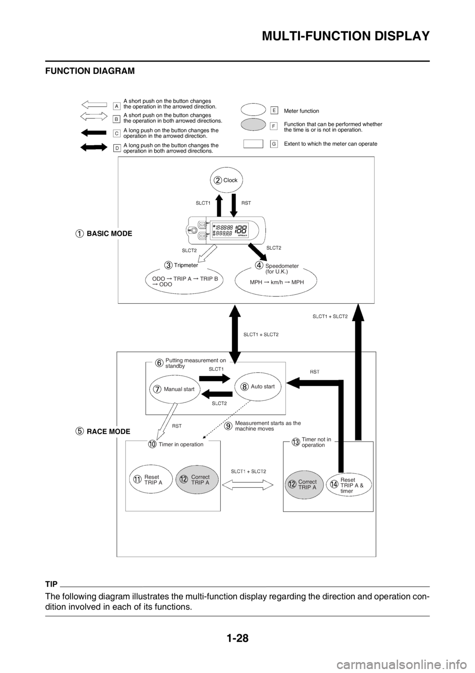
FUNCTION DIAGRAM
TIP
The following diagram illustrates the multi-function display regarding the direction and operation con-
dition involved in each of its functions.
A short push on the button changes
the operation in the arrowed direction.
A short push on the button changes
the operation in both arrowed directions.
A long push on the button changes the
operation in the arrowed direction.
A long push on the button changes the
operation in both arrowed directions.Meter function
Function that can be performed whether
the time is or is not in operation.
Extent to which the meter can operate
Clock
BASIC MODE
Tripmeter
ODO TRIP A TRIP B ODO
Speedometer
(for U.K.)
MPH
km/h MPH
Putting measurement on
standby
Manual startAuto start
RACE MODE
Timer in operation
Reset
TRIP ACorrect
TRIP AMeasurement starts as the
machine moves
Timer not in
operation
Correct
TRIP AReset
TRIP A &
timer
Page 53 of 432

2
SPECIFICATIONS
GENERAL SPECIFICATIONS......................................................................... 2-1
ENGINE SPECIFICATIONS............................................................................. 2-2
CHASSIS SPECIFICATIONS........................................................................... 2-7
ELECTRICAL SPECIFICATIONS.................................................................. 2-10
TIGHTENING TORQUES............................................................................... 2-12
GENERAL TIGHTENING TORQUE SPECIFICATIONS .......................... 2-12
ENGINE TIGHTENING TORQUES .......................................................... 2-13
CHASSIS TIGHTENING TORQUES ........................................................ 2-16
LUBRICATION POINTS AND LUBRICANT TYPES..................................... 2-20
ENGINE .................................................................................................... 2-20
CHASSIS .................................................................................................. 2-21
LUBRICATION SYSTEM CHART AND DIAGRAMS..................................... 2-23
LUBRICATION DIAGRAMS ..................................................................... 2-23
CABLE ROUTING DIAGRAM........................................................................ 2-31
Page 76 of 432
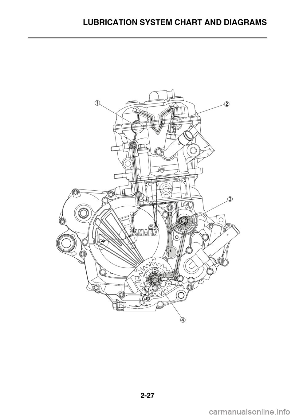
LUBRICATION SYSTEM CHART AND DIAGRAMS
2-23
EAS2GBB071
LUBRICATION SYSTEM CHART AND DIAGRAMS
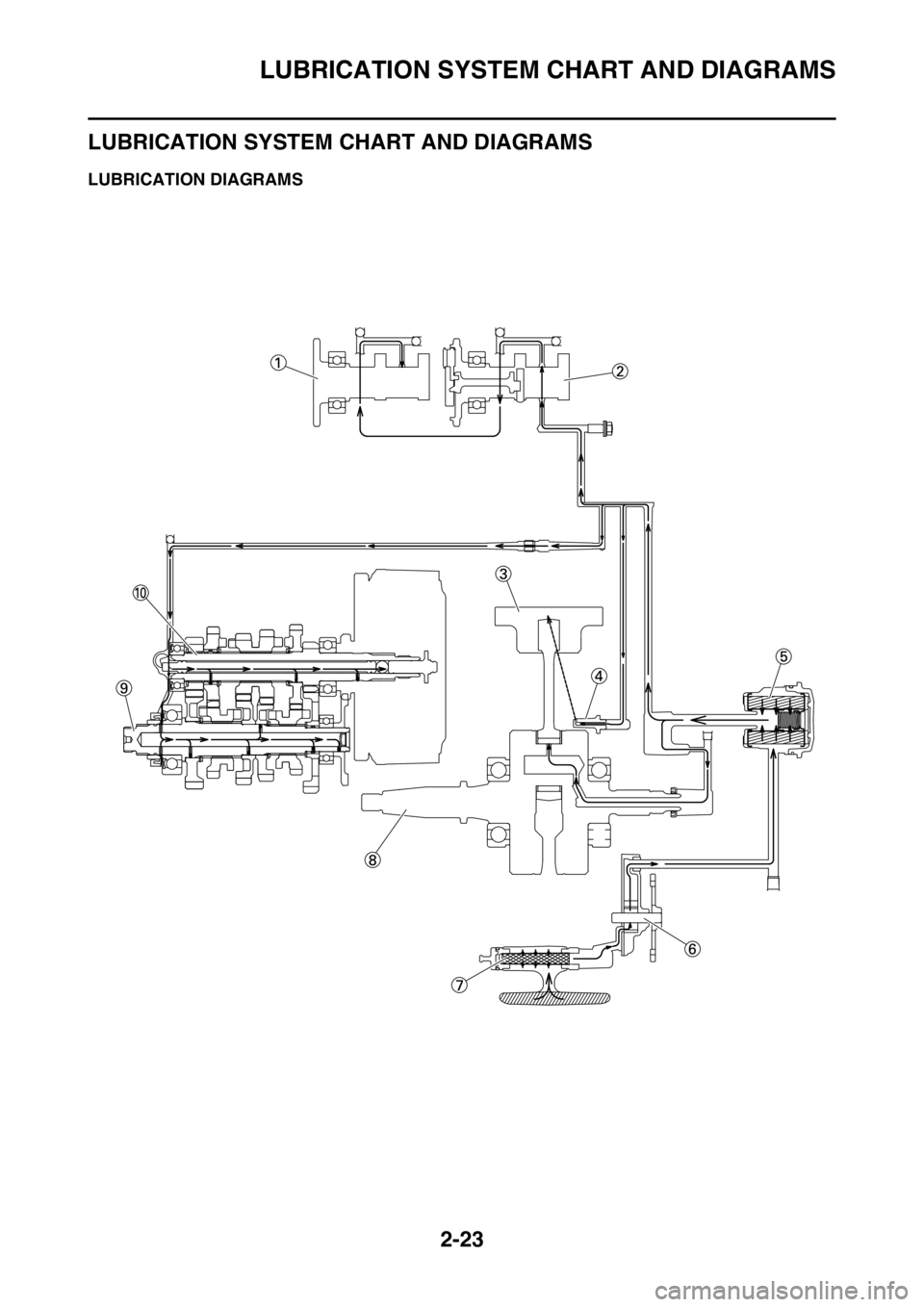
EAS2GBB072LUBRICATION DIAGRAMS
Page 77 of 432

LUBRICATION SYSTEM CHART AND DIAGRAMS
2-24
1. Intake camshaft
2. Exhaust camshaft
3. Piston
4. Oil nozzle
5. Oil filter element
6. Oil pump
7. Oil strainer
8. Crankshaft
9. Drive axle
10. Main axle
Page 78 of 432
LUBRICATION SYSTEM CHART AND DIAGRAMS
2-25
Page 79 of 432

LUBRICATION SYSTEM CHART AND DIAGRAMS
2-26
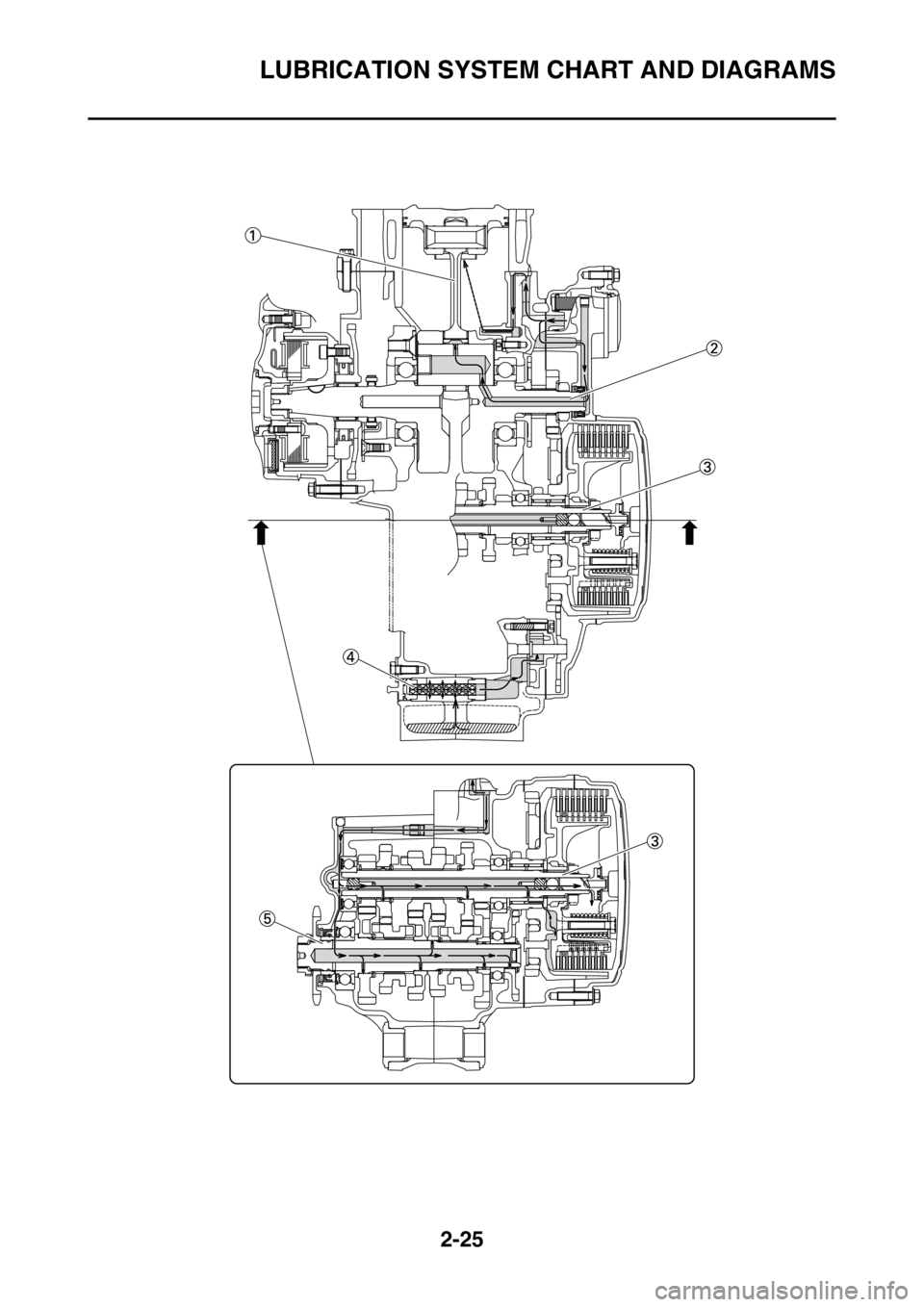
1. Connecting rod
2. Crankshaft
3. Main axle
4. Oil strainer
5. Drive axle
Page 80 of 432
LUBRICATION SYSTEM CHART AND DIAGRAMS
2-27
Page 81 of 432

LUBRICATION SYSTEM CHART AND DIAGRAMS
2-28
1. Exhaust camshaft
2. Intake camshaft
3. Oil filter element
4. Oil pump