reset YAMAHA WR 250F 2017 Owners Manual
[x] Cancel search | Manufacturer: YAMAHA, Model Year: 2017, Model line: WR 250F, Model: YAMAHA WR 250F 2017Pages: 432, PDF Size: 14.14 MB
Page 24 of 432
BASIC SERVICE INFORMATION
1-10
ECA
NOTICE
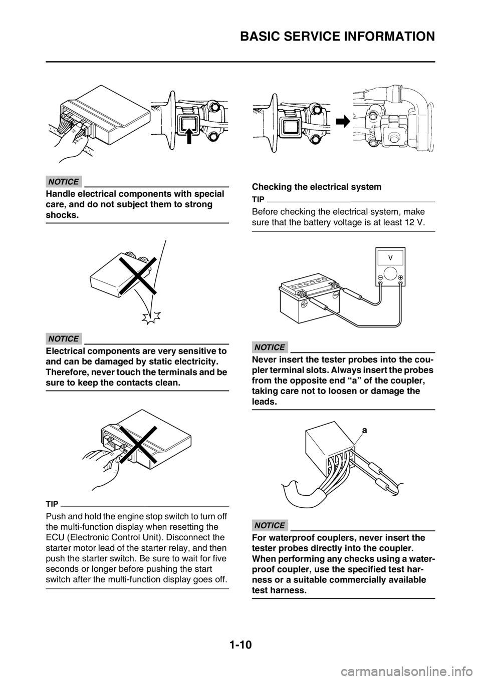
Handle electrical components with special
care, and do not subject them to strong
shocks.
ECA
NOTICE
Electrical components are very sensitive to
and can be damaged by static electricity.
Therefore, never touch the terminals and be
sure to keep the contacts clean.
TIP
Push and hold the engine stop switch to turn off
the multi-function display when resetting the
ECU (Electronic Control Unit). Disconnect the
starter motor lead of the starter relay, and then
push the starter switch. Be sure to wait for five
seconds or longer before pushing the start
switch after the multi-function display goes off.Checking the electrical system
TIP
Before checking the electrical system, make
sure that the battery voltage is at least 12 V.
ECA
NOTICE
Never insert the tester probes into the cou-
pler terminal slots. Always insert the probes
from the opposite end “a” of the coupler,
taking care not to loosen or damage the
leads.
ECA
NOTICE
For waterproof couplers, never insert the
tester probes directly into the coupler.
When performing any checks using a water-
proof coupler, use the specified test har-
ness or a suitable commercially available
test harness.
a
Page 36 of 432
MULTI-FUNCTION DISPLAY
1-22
EAS2GBB042
MULTI-FUNCTION DISPLAYEWA
WARNING
Be sure to stop the machine before making
any setting changes to the multi-function
display.
The multi-function display is equipped with the
following:
BASIC MODE:
• Speedometer
•Clock
• Two tripmeters (which shows the distance
that has been traveled since it was last set to
zero)
RACE MODE:
• Timer (which shows the time that has been
accumulated since the start of timer measure-
ment)
• Tripmeter (which shows the accumulated
travel distance in timer measurement)
• Change tripmeter digits (capable of change to
any given ones)
EAS2GBB043DESCRIPTION
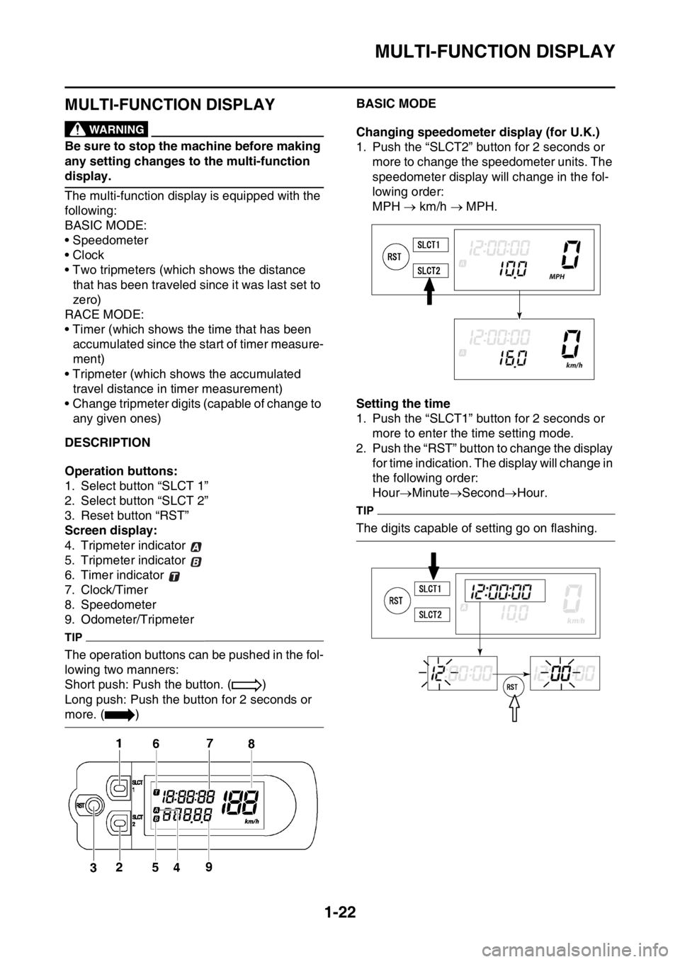
Operation buttons:
1. Select button “SLCT 1”
2. Select button “SLCT 2”
3. Reset button “RST”
Screen display:
4. Tripmeter indicator
5. Tripmeter indicator
6. Timer indicator
7. Clock/Timer
8. Speedometer
9. Odometer/Tripmeter
TIP
The operation buttons can be pushed in the fol-
lowing two manners:
Short push: Push the button. ( )
Long push: Push the button for 2 seconds or
more. ( )
EAS2GBB044BASIC MODE
Changing speedometer display (for U.K.)
1. Push the “SLCT2” button for 2 seconds or
more to change the speedometer units. The
speedometer display will change in the fol-
lowing order:
MPH km/h MPH.
Setting the time
1. Push the “SLCT1” button for 2 seconds or
more to enter the time setting mode.
2. Push the “RST” button to change the display
for time indication. The display will change in
the following order:
HourMinuteSecondHour.
TIP
The digits capable of setting go on flashing.
Page 37 of 432
MULTI-FUNCTION DISPLAY
1-23
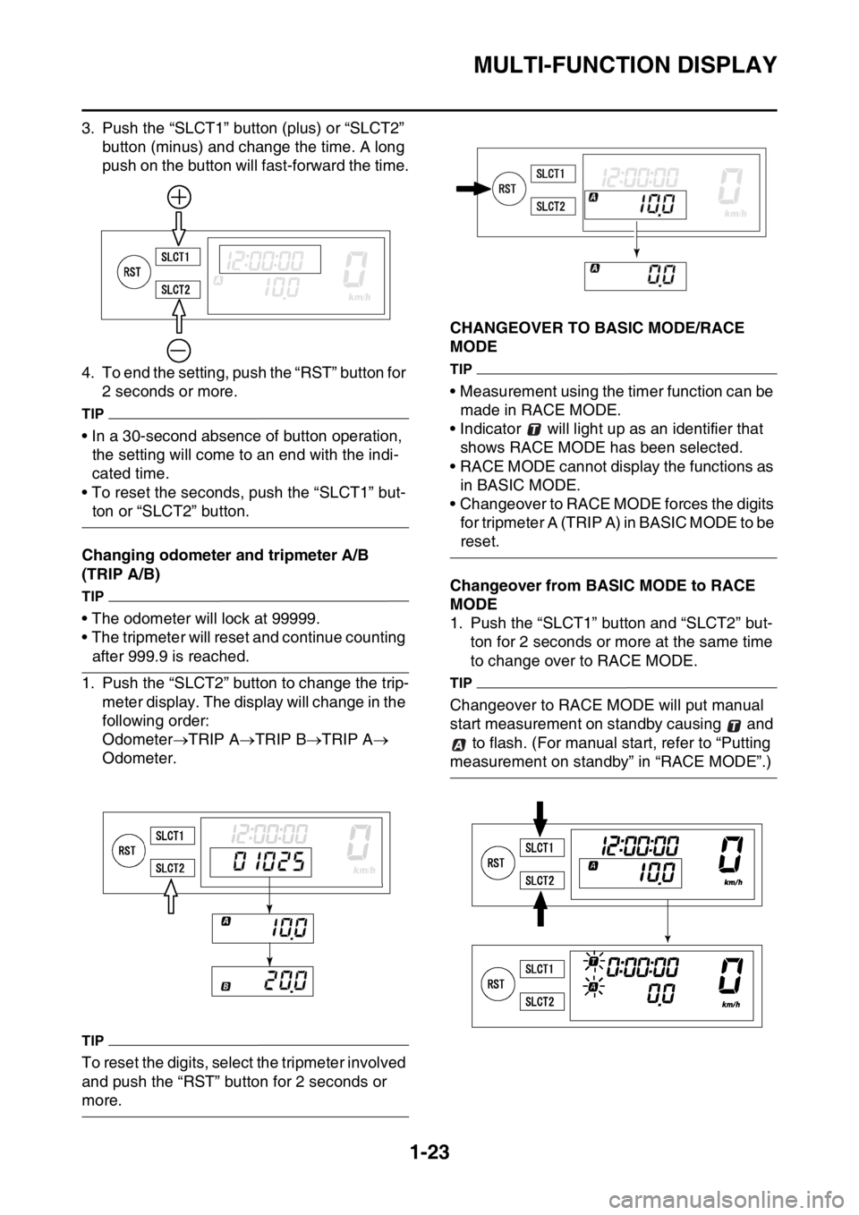
3. Push the “SLCT1” button (plus) or “SLCT2”
button (minus) and change the time. A long
push on the button will fast-forward the time.
4. To end the setting, push the “RST” button for
2 seconds or more.
TIP
• In a 30-second absence of button operation,
the setting will come to an end with the indi-
cated time.
• To reset the seconds, push the “SLCT1” but-
ton or “SLCT2” button.
Changing odometer and tripmeter A/B
(TRIP A/B)
TIP
• The odometer will lock at 99999.
• The tripmeter will reset and continue counting
after 999.9 is reached.
1. Push the “SLCT2” button to change the trip-
meter display. The display will change in the
following order:
OdometerTRIP ATRIP BTRIP A
Odometer.
TIP
To reset the digits, select the tripmeter involved
and push the “RST” button for 2 seconds or
more.
EAS2GBB045CHANGEOVER TO BASIC MODE/RACE
MODE
TIP
• Measurement using the timer function can be
made in RACE MODE.
• Indicator will light up as an identifier that
shows RACE MODE has been selected.
• RACE MODE cannot display the functions as
in BASIC MODE.
• Changeover to RACE MODE forces the digits
for tripmeter A (TRIP A) in BASIC MODE to be
reset.
Changeover from BASIC MODE to RACE
MODE
1. Push the “SLCT1” button and “SLCT2” but-
ton for 2 seconds or more at the same time
to change over to RACE MODE.
TIP
Changeover to RACE MODE will put manual
start measurement on standby causing and
to flash. (For manual start, refer to “Putting
measurement on standby” in “RACE MODE”.)
Page 39 of 432
MULTI-FUNCTION DISPLAY
1-25
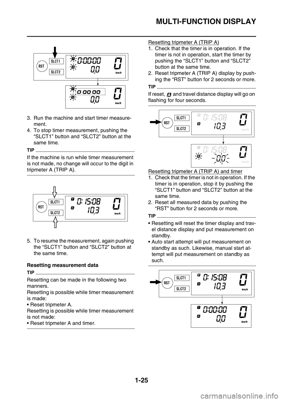
3. Run the machine and start timer measure-
ment.
4. To stop timer measurement, pushing the
“SLCT1” button and “SLCT2” button at the
same time.
TIP
If the machine is run while timer measurement
is not made, no change will occur to the digit in
tripmeter A (TRIP A).
5. To resume the measurement, again pushing
the “SLCT1” button and “SLCT2” button at
the same time.
Resetting measurement data
TIP
Resetting can be made in the following two
manners.
Resetting is possible while timer measurement
is made:
• Reset tripmeter A.
Resetting is possible while timer measurement
is not made:
• Reset tripmeter A and timer.Resetting tripmeter A (TRIP A)
1. Check that the timer is in operation. If the
timer is not in operation, start the timer by
pushing the “SLCT1” button and “SLCT2”
button at the same time.
2. Reset tripmeter A (TRIP A) display by push-
ing the “RST” button for 2 seconds or more.
TIP
If reset, and travel distance display will go on
flashing for four seconds.
Resetting tripmeter A (TRIP A) and timer
1. Check that the timer is not in operation. If the
timer is in operation, stop it by pushing the
“SLCT1” button and “SLCT2” button at the
same time.
2. Reset all measured data by pushing the
“RST” button for 2 seconds or more.
TIP
• Resetting will reset the timer display and trav-
el distance display and put measurement on
standby.
• Auto start attempt will put measurement on
standby as such. Likewise, manual start at-
tempt will put measurement on standby as
such.
Page 42 of 432
MULTI-FUNCTION DISPLAY
1-28
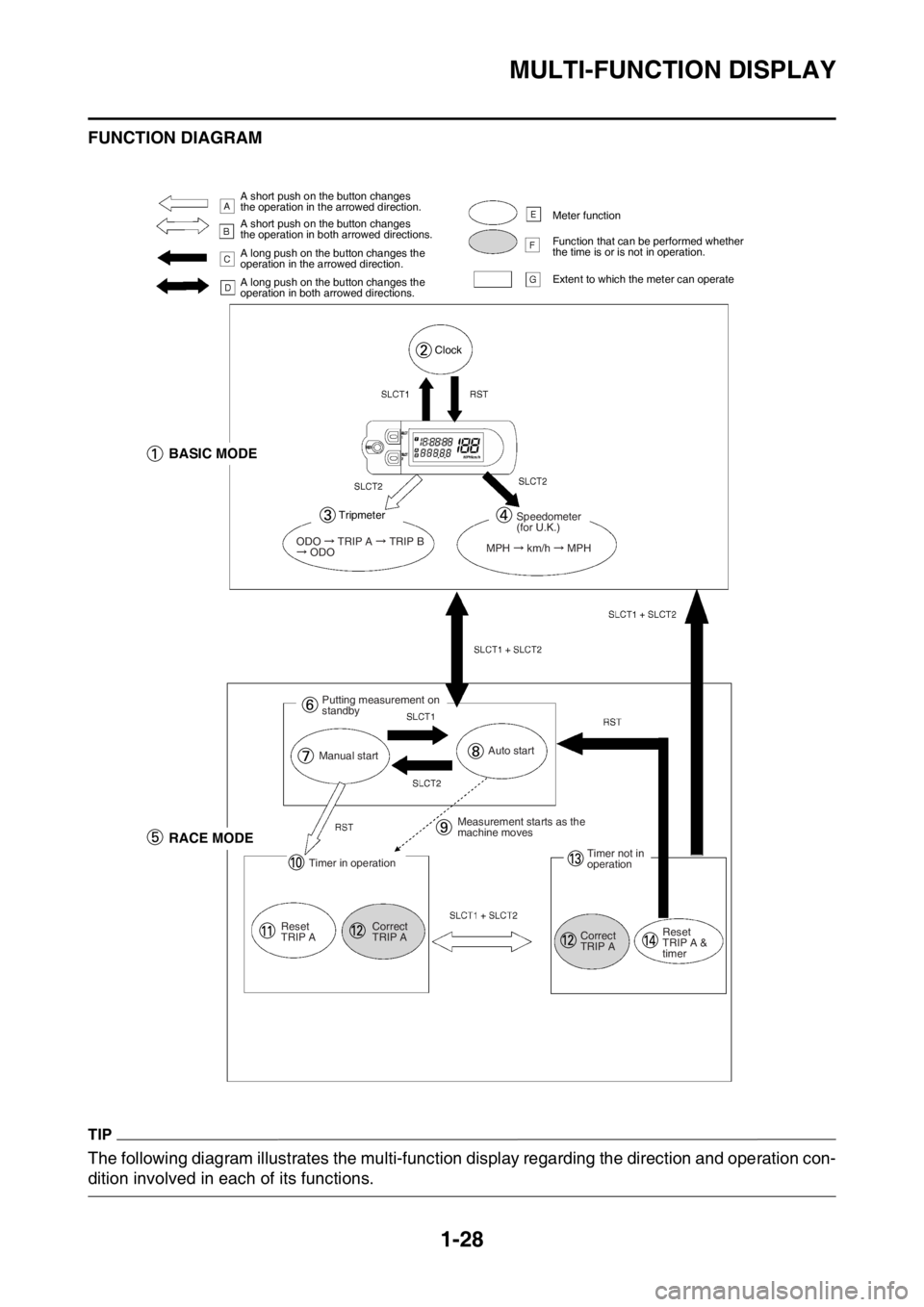
FUNCTION DIAGRAM
TIP
The following diagram illustrates the multi-function display regarding the direction and operation con-
dition involved in each of its functions.
A short push on the button changes
the operation in the arrowed direction.
A short push on the button changes
the operation in both arrowed directions.
A long push on the button changes the
operation in the arrowed direction.
A long push on the button changes the
operation in both arrowed directions.Meter function
Function that can be performed whether
the time is or is not in operation.
Extent to which the meter can operate
Clock
BASIC MODE
Tripmeter
ODO TRIP A TRIP B ODO
Speedometer
(for U.K.)
MPH
km/h MPH
Putting measurement on
standby
Manual startAuto start
RACE MODE
Timer in operation
Reset
TRIP ACorrect
TRIP AMeasurement starts as the
machine moves
Timer not in
operation
Correct
TRIP AReset
TRIP A &
timer
Page 43 of 432

MULTI-FUNCTION DISPLAY
1-29
A.A short push on the button changes the oper-
ation in the arrowed direction.
B.A short push on the button changes the oper-
ation in both arrowed directions.
C.A long push on the button changes the oper-
ation in the arrowed direction.
D.A long push on the button changes the oper-
ation in both arrowed directions.
E.Meter function
F.Function that can be performed whether the
time is or is not in operation.
G.Extent to which the meter can operate
1. BASIC MODE
2. Clock
3. Trip meter
4. Speedometer (for U.K.)
5. RACE MODE
6. Putting measurement on standby
7. Manual start
8. Auto start
9. Measurement starts as the machine moves
10.Timer in operation
11.Reset TRIP A
12.Correct TRIP A
13.Timer not in operation
14.Reset TRIP A and timer
Page 149 of 432
CHASSIS
4-6
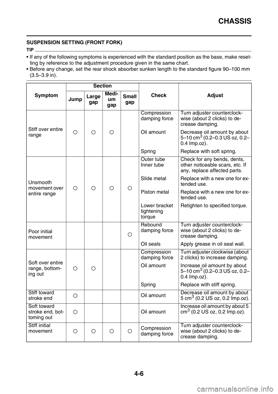
EAS2GBB148SUSPENSION SETTING (FRONT FORK)
TIP
• If any of the following symptoms is experienced with the standard position as the base, make reset-
ting by reference to the adjustment procedure given in the same chart.
• Before any change, set the rear shock absorber sunken length to the standard figure 90–100 mm
(3.5–3.9 in).
SymptomSection
Check Adjust
JumpLarge
gapMedi-
um
gapSmall
gap
Stiff over entire
rangeCompression
damping forceTurn adjuster counterclock-
wise (about 2 clicks) to de-
crease damping.
Oil amount Decrease oil amount by about
5–10 cm
3 (0.2–0.3 US oz, 0.2–
0.4 Imp.oz).
Spring Replace with soft spring.
Unsmooth
movement over
entire rangeOuter tube
Inner tubeCheck for any bends, dents,
other noticeable scars, etc. If
any, replace affected parts.
Slide metal Replace with a new one for ex-
tended use.
Piston metal Replace with a new one for ex-
tended use.
Lower bracket
tightening
torqueRetighten to specified torque.
Poor initial
movementRebound
damping forceTurn adjuster counterclock-
wise (about 2 clicks) to de-
crease damping.
Oil seals Apply grease in oil seal wall.
Soft over entire
range, bottom-
ing outCompression
damping forceTurn adjuster clockwise (about
2 clicks) to increase damping.
Oil amount Increase oil amount by about
5–10 cm
3 (0.2–0.3 US oz, 0.2–
0.4 Imp.oz).
Spring Replace with stiff spring.
Stiff toward
stroke endOil amountDecrease oil amount by about
5 cm
3 (0.2 US oz, 0.2 Imp.oz).
Soft toward
stroke end, bot-
toming outOil amountIncrease oil amount by about 5
cm
3 (0.2 US oz, 0.2 Imp.oz).
Stiff initial
movementCompression
damping forceTurn adjuster counterclock-
wise (about 2 clicks) to de-
crease damping.
Page 150 of 432
CHASSIS
4-7
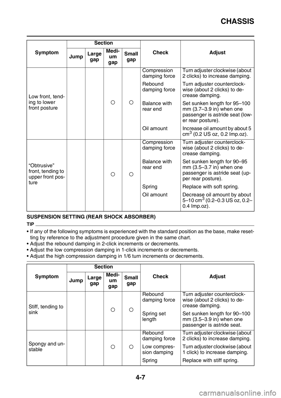
EAS2GBB149SUSPENSION SETTING (REAR SHOCK ABSORBER)
TIP
• If any of the following symptoms is experienced with the standard position as the base, make reset-
ting by reference to the adjustment procedure given in the same chart.
• Adjust the rebound damping in 2-click increments or decrements.
• Adjust the low compression damping in 1-click increments or decrements.
• Adjust the high compression damping in 1/6 turn increments or decrements. Low front, tend-
ing to lower
front postureCompression
damping forceTurn adjuster clockwise (about
2 clicks) to increase damping.
Rebound
damping forceTurn adjuster counterclock-
wise (about 2 clicks) to de-
crease damping.
Balance with
rear endSet sunken length for 95–100
mm (3.7–3.9 in) when one
passenger is astride seat (low-
er rear posture).
Oil amount Increase oil amount by about 5
cm
3 (0.2 US oz, 0.2 Imp.oz).
“Obtrusive”
front, tending to
upper front pos-
tureCompression
damping forceTurn adjuster counterclock-
wise (about 2 clicks) to de-
crease damping.
Balance with
rear endSet sunken length for 90–95
mm (3.5–3.7 in) when one
passenger is astride seat (up-
per rear posture).
Spring Replace with soft spring.
Oil amount Decrease oil amount by about
5–10 cm
3 (0.2–0.3 US oz, 0.2–
0.4 Imp.oz).
SymptomSection
Check Adjust
JumpLarge
gapMedi-
um
gapSmall
gap
Stiff, tending to
sinkRebound
damping forceTurn adjuster counterclock-
wise (about 2 clicks) to de-
crease damping.
Spring set
lengthSet sunken length for 90–100
mm (3.5–3.9 in) when one
passenger is astride seat.
Spongy and un-
stableRebound
damping forceTurn adjuster clockwise (about
2 clicks) to increase damping.
Low compres-
sion dampingTurn adjuster clockwise (about
1 click) to increase damping.
Spring Replace with stiff spring. SymptomSection
Check Adjust
JumpLarge
gapMedi-
um
gapSmall
gap
Page 371 of 432

FUEL INJECTION SYSTEM
9-35
6. Condition
The current conditions are displayed. (Detected/Recovered)
7. Symptom
The symptoms of the detected malfunction are displayed.
8. Diagnosis code
The diagnosis codes related to the detected malfunction are displayed.
9. FFD (only for models that can display freeze frame data)
The mark “ ” is displayed when the freeze frame data is available.
10.ECU conduction time (hour: minute: second)
The total ECU conduction time (total hours the vehicle’s start switch was ON) when the malfunc-
tion was detected is displayed.
11.Number of main switch operation after detection
The number of times the meter light comes on by pushing the start switch between the malfunction
detection and code reading is displayed.
12.Number of occurrences
The number of malfunction occurrences between the malfunction detection and code reading is
displayed.
EAS2GBB377TROUBLESHOOTING DETAILS
This section describes the measures per fault code number displayed on the diagnostic tool. Check
and service the items or components that are the probable cause of the malfunction following the or-
der given.
After the check and service of the malfunctioning part have been completed, reset the diagnostic tool
display according to the reinstatement method.
Fault code No.:
Fault code number displayed on the diagnostic tool when the engine failed to work normally.
Diagnostic code No.:
Diagnostic code number to be used when the diagnostic mode is operated.
Fault code No. 12
ItemCrankshaft position sensor: no normal signals are received
from the crankshaft position sensor.
Fail-safe systemUnable to start engine
Unable to drive vehicle
Diagnostic code No.—
Diagnostic tool display—
Procedure—
ItemProbable cause of malfunc-
tion and checkMaintenance jobConfirmation of service
completion
1 Connection of crankshaft po-
sition sensor coupler.
Check the locking condition
of the coupler.
Disconnect the coupler and
check the pins (bent or bro-
ken terminals and locking
condition of the pins).Improperly connected
Connect the coupler securely
or repair/replace the wire har-
ness.Crank the engine.
Fault code number is not dis-
played Service is finished.
Fault code number is dis-
played Go to item 2.
Page 425 of 432

LIST OF SELF-DIAGNOSTIC AND FAIL-SAFE ACTIONS
10-6
SENSOR OPERATION TABLE
Diag-
nostic
code
No.Item Display Procedure
01 Throttle position sensor sig-
nal
• Fully closed position
• Fully opened position• 11–14
• 109–116• Check with throttle valve
fully closed.
• Check with throttle valve
fully open.
03 Intake air pressure Displays the intake air pres-
sure.Operate the throttle while
pushing the start switch. (If
the display value changes,
the performance is OK.)
05 Intake air temperature Displays the intake air tem-
perature.Compare the actually mea-
sured intake air tempera-
ture with the Yamaha
diagnostic tool display val-
ue.
06 Coolant temperature When engine is cold: Dis-
plays temperature closer to
air temperature.
When engine is hot: Displays
current coolant temperature.Compare the actually mea-
sured coolant temperature
with the Yamaha diagnostic
tool display value.
07 Vehicle speed pulses Vehicle speed pulse
0–999Check that the number in-
creases when the front
wheel is rotated. The num-
ber is cumulative and does
not reset each time the
wheel is stopped.
08 Lean angle sensor
• Upright
• OverturnedDisplays the output voltage.
• 0.4–1.4
• 3.7–4.4Remove the lean angle
sensor, and incline it more
than 45 degrees.
09 Monitor voltage Displays the fuel system volt-
age.
• Approximately 12.0 (V)—
21 Neutral switch
• Gear in neutral
• Gear not in neutral•ON
•OFFOperate the shift pedal.
60 EEPROM fault code display
• No fault
• CO adjustment value
• Setting tool adjustment
values 0–8 for fuel injec-
tion amount or ignition tim-
ing•00
•01
•07—
61 Malfunction history ( )
code display *1
• There is no history.
• There is some history.•00
• Other: Displays the fault
code of ( ).—