width YAMAHA WR 250F 2017 Owners Manual
[x] Cancel search | Manufacturer: YAMAHA, Model Year: 2017, Model line: WR 250F, Model: YAMAHA WR 250F 2017Pages: 432, PDF Size: 14.14 MB
Page 54 of 432

GENERAL SPECIFICATIONS
2-1
EAS2GBB061
GENERAL SPECIFICATIONS
Model
Model 2GBB (USA)
2GBC (CAN)
2GBD (EUR)
2GBE (AUS) (NZL) (ZAF)
Dimensions
Overall length 2165 mm (85.2 in)
Overall width 825 mm (32.5 in)
Overall height 1280 mm (50.4 in)
Seat height 965 mm (38.0 in)
Wheelbase 1465 mm (57.7 in)
Ground clearance 325 mm (12.80 in)
Weight
Curb weight 117 kg (258 lb) (USA) (CAN)
118 kg (260 lb) (EUR) (AUS) (NZL) (ZAF)
Page 55 of 432

ENGINE SPECIFICATIONS
2-2
EAS2GBB062
ENGINE SPECIFICATIONS
Engine
Engine type Liquid cooled 4-stroke, DOHC
Displacement 250 cm
3
Number of cylinders Single cylinder
Bore stroke 77.0 53.6 mm (3.03 2.11 in)
Compression ratio 13.5:1
Starting system Electric starter and kickstarter
Fuel
Recommended fuel Premium unleaded gasoline only
Fuel tank capacity 7.5 L (2.0 US gal, 1.7 Imp.gal)
Fuel reserve amount 2.1 L (0.55 US gal, 0.46 lmp.gal)
Engine oil
Lubrication system Wet sump
Recommended brand YAMALUBE
Type SAE 10W-40, SAE 10W-50, SAE 15W-40,
SAE 20W-40 or SAE 20W-50
Recommended engine oil grade API service SG type or higher, JASO standard
MA
Engine oil quantity
Quantity (disassembled) 1.10 L (1.16 US qt, 0.97 Imp.qt)
Oil change 0.83 L (0.88 US qt, 0.73 Imp.qt)
With oil filter removal 0.85 L (0.90 US qt, 0.75 Imp.qt)
Oil filter
Oil filter type Paper
Bypass valve opening pressure 40.0–80.0 kPa (0.40–0.80 kgf/cm
2,
5.8–11.6 psi)
Oil pump
Oil pump type Trochoid
Inner-rotor-to-outer-rotor-tip clearance 0.000–0.150 mm (0.0000–0.0059 in)
Limit 0.23 mm (0.0091 in)
Outer-rotor-to-oil-pump-housing clearance 0.13–0.18 mm (0.0051–0.0071 in)
Limit 0.25 mm (0.0098 in)
Oil-pump-housing-to-inner-and-outer-rotor
clearance 0.06–0.11 mm (0.0024–0.0043 in)
Limit 0.18 mm (0.0071 in)
Cooling system
Radiator (including all routes) 1.00 L (1.06 US qt, 0.88 Imp.qt)
Radiator capacity 0.56 L (0.59 US qt, 0.49 Imp.qt)
Radiator cap valve opening pressure 107.9–137.3 kPa (1.08–1.37 kg/cm
2,
15.6–19.9 psi)
Radiator core
Width 112.6 mm (4.43 in)
Height 235.0 mm (9.25 in)
Depth 28.0 mm (1.10 in)
Water pump
Water pump type Single suction centrifugal pump
Spark plug(s)
Manufacturer/model NGK/LMAR8G
Spark plug gap 0.7–0.8 mm (0.028–0.031 in)
Page 56 of 432

ENGINE SPECIFICATIONS
2-3
Cylinder head
Combustion chamber volume 12.07–12.87 cm3 (0.74–0.79 cu.in)
Warpage limit 0.05 mm (0.0020 in)
Camshaft
Drive system Chain drive (left)
Camshaft cap inside diameter 22.000–22.021 mm (0.8661–0.8670 in)
Camshaft journal diameter 21.959–21.972 mm (0.8645–0.8650 in)
Camshaft-journal-to-camshaft-cap clearance 0.028–0.062 mm (0.0011–0.0024 in)
Camshaft lobe dimensions
Lobe height (Intake) 31.730–31.830 mm (1.2492–1.2531 in)
Limit 31.630 mm (1.2453 in)
Base circle diameter (Intake) 22.450–22.550 mm (0.8839–0.8878 in)
Limit 22.350 mm (0.8799 in)
Lobe height (Exhaust) 33.370–33.470 mm (1.3138–1.3177 in)
Limit 33.270 mm (1.3098 in)
Base circle diameter (Exhaust) 25.211–25.311 mm (0.9926–0.9965 in)
Limit 25.111 mm (0.9886 in)
Camshaft runout limit 0.030 mm (0.0012 in)
Timing chain
Tensioning system Automatic
Valve, valve seat, valve guide
Valve clearance (cold)
Intake 0.12–0.19 mm (0.0047–0.0075 in)
Exhaust 0.17–0.24 mm (0.0067–0.0094 in)
Valve dimensions
Valve head diameter (intake) 30.90–31.10 mm (1.2165–1.2244 in)
Valve head diameter (exhaust) 24.90–25.10 mm (0.9803–0.9882 in)
Valve face width (intake) 1.697 mm (0.0668 in)
Valve face width (exhaust) 1.909 mm (0.0752 in)
Valve seat contact width (intake) 0.90–1.10 mm (0.0354–0.0433 in)
Valve seat contact width (exhaust) 0.90–1.10 mm (0.0354–0.0433 in)
Valve margin thickness (intake) 1.20 mm (0.0472 in)
Valve margin thickness (exhaust) 0.85 mm (0.0335 in)
Valve stem diameter (intake) 4.975–4.990 mm (0.1959–0.1965 in)
Limit 4.945 mm (0.1947 in)
Valve stem diameter (exhaust) 4.460–4.475 mm (0.1756–0.1762 in)
Limit 4.430 mm (0.1744 in)
Valve guide inside diameter (intake) 5.000–5.012 mm (0.1969–0.1973 in)
Limit 5.050 mm (0.1988 in)
Valve guide inside diameter (exhaust) 4.500–4.512 mm (0.1772–0.1776 in)
Limit 4.550 mm (0.1791 in)
Valve-stem-to-valve-guide clearance (intake) 0.010–0.037 mm (0.0004–0.0015 in)
Limit 0.080 mm (0.0032 in)
Valve-stem-to-valve-guide clearance (exhaust) 0.025–0.052 mm (0.0010–0.0020 in)
Limit 0.100 mm (0.0039 in)
Valve stem runout 0.010 mm (0.0004 in)
Page 57 of 432

ENGINE SPECIFICATIONS
2-4
Valve spring
Free length (intake) 36.69 mm (1.44 in)
Limit 34.85 mm (1.37 in)
Free length (exhaust) 34.86 mm (1.37 in)
Limit 33.11 mm (1.30 in)
Installed length (intake) 31.40 mm (1.24 in)
Installed length (exhaust) 28.50 mm (1.12 in)
Spring rate K1 (intake) 29.65 N/mm (3.02 kgf/mm, 169.30 lbf/in)
Spring rate K2 (intake) 39.31 N/mm (4.01 kgf/mm, 224.46 lbf/in)
Spring rate K1 (exhaust) 23.11 N/mm (2.36 kgf/mm, 131.96 lbf/in)
Spring rate K2 (exhaust) 30.88 N/mm (3.15 kgf/mm, 176.32 lbf/in)
Installed compression spring force (intake) 146.00–168.00 N (14.89–17.13 kgf,
32.82–37.77 lbf)
Installed compression spring force (exhaust) 137.00–157.00 N (13.97–16.01 kgf,
30.80–35.29 lbf)
Spring tilt (intake) 2.5 °/1.6 mm (2.5 °/0.06 in)
Spring tilt (exhaust) 2.5 °/1.5 mm (2.5 °/0.06 in)
Winding direction (intake) Clockwise
Winding direction (exhaust) Clockwise
Cylinder
Bore 77.000–77.010 mm (3.0315–3.0319 in)
Taper limit 0.050 mm (0.0020 in)
Out of round limit 0.050 mm (0.0020 in)
Piston
Piston-to-cylinder clearance 0.030–0.055 mm (0.0012–0.0022 in)
Limit 0.15 mm (0.006 in)
Diameter 76.955–76.970 mm (3.0297–3.0303 in)
Measuring point (from piston skirt bottom) 6.0 mm (0.24 in)
Offset 0.00 mm (0.0000 in)
Piston pin bore inside diameter 16.002–16.013 mm (0.6300–0.6304 in)
Limit 16.043 mm (0.6316 in)
Piston pin outside diameter 15.991–16.000 mm (0.6296–0.6299 in)
Limit 15.971 mm (0.6288 in)
Piston ring
Top ring
Ring type Barrel
Dimensions (B T) 0.90 2.70 mm (0.04 0.11 in)
End gap (installed) 0.15–0.25 mm (0.0059–0.0098 in)
Limit 0.50 mm (0.0197 in)
Ring side clearance 0.030–0.065 mm (0.0012–0.0026 in)
Limit 0.115 mm (0.0045 in)
Oil ring
Dimensions (B T) 1.50 2.25 mm (0.06 0.89 in)
End gap (installed) 0.10–0.35 mm (0.0039–0.0138 in)
Crankshaft
Crank assembly width 55.95–56.00 mm (2.203–2.205 in)
Runout limit 0.030 mm (0.0012 in)
Big end side clearance 0.150–0.450 mm (0.0059–0.0177 in)
Balancer
Balancer drive method Gear
Page 245 of 432
CAMSHAFT
6-16
c. Install the dowel pins and the camshaft
caps.
TIP
• Tighten the camshaft cap bolts in a crisscross
pattern from innermost to outer caps.
• Do not turn the camshaft when measuring the
camshaft journal-to-camshaft cap clearance.
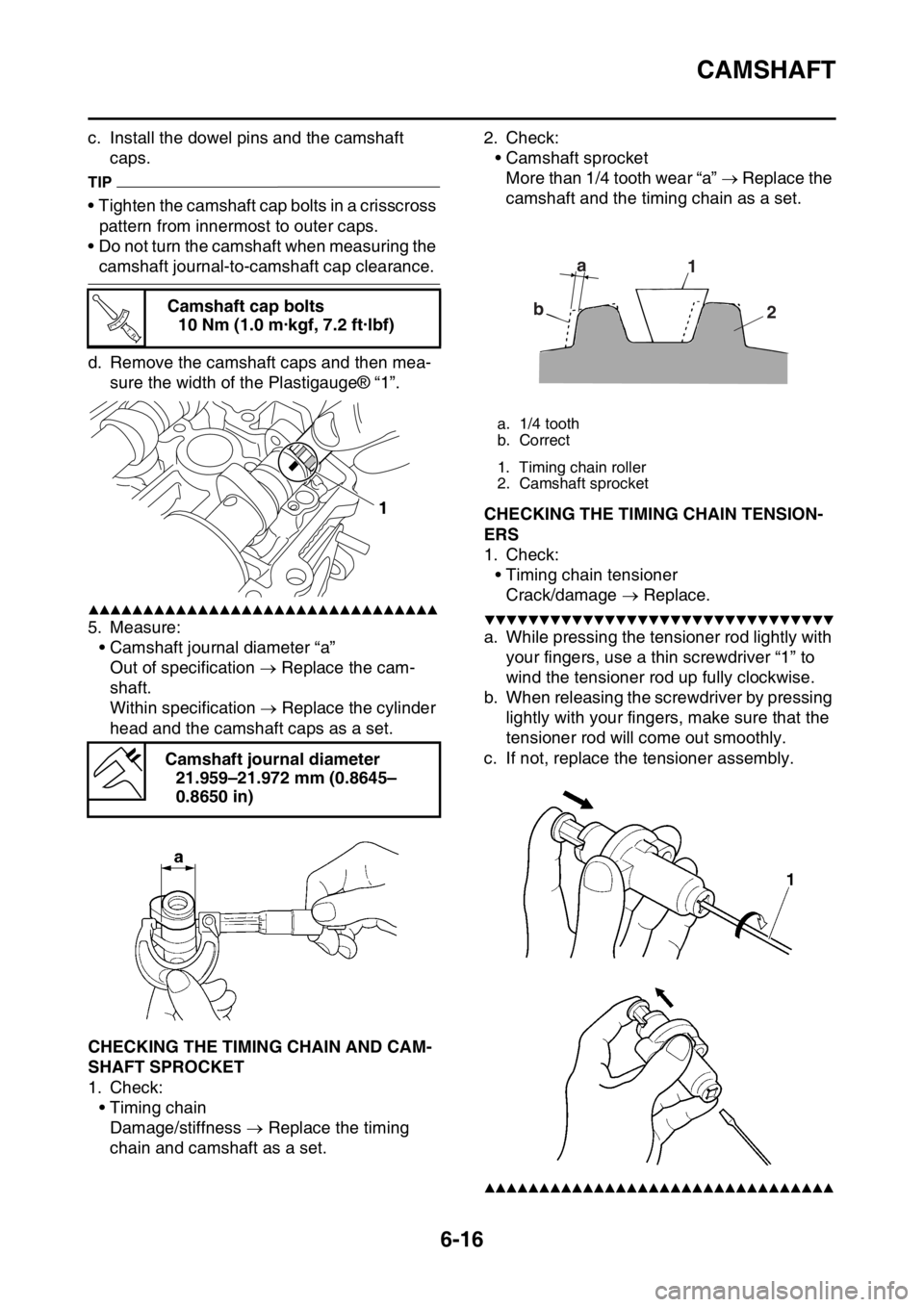
d. Remove the camshaft caps and then mea-
sure the width of the Plastigauge® “1”.
▲▲▲▲▲▲▲▲▲▲▲▲▲▲▲▲▲▲▲▲▲▲▲▲▲▲▲▲▲▲▲▲
5. Measure:
• Camshaft journal diameter “a”
Out of specification Replace the cam-
shaft.
Within specification Replace the cylinder
head and the camshaft caps as a set.
EAS2GBB240CHECKING THE TIMING CHAIN AND CAM-
SHAFT SPROCKET
1. Check:
•Timing chain
Damage/stiffness Replace the timing
chain and camshaft as a set.2. Check:
• Camshaft sprocket
More than 1/4 tooth wear “a” Replace the
camshaft and the timing chain as a set.
EAS2GBB241CHECKING THE TIMING CHAIN TENSION-
ERS
1. Check:
• Timing chain tensioner
Crack/damage Replace.
▼▼▼▼▼▼▼▼▼▼▼▼▼▼▼▼▼▼▼▼▼▼▼▼▼▼▼▼▼▼▼▼
a. While pressing the tensioner rod lightly with
your fingers, use a thin screwdriver “1” to
wind the tensioner rod up fully clockwise.
b. When releasing the screwdriver by pressing
lightly with your fingers, make sure that the
tensioner rod will come out smoothly.
c. If not, replace the tensioner assembly.
▲▲▲▲▲▲▲▲▲▲▲▲▲▲▲▲▲▲▲▲▲▲▲▲▲▲▲▲▲▲▲▲
Camshaft cap bolts
10 Nm (1.0 m·kgf, 7.2 ft·lbf)
Camshaft journal diameter
21.959–21.972 mm (0.8645–
0.8650 in)
T R..
1
a. 1/4 tooth
b. Correct
1. Timing chain roller
2. Camshaft sprocket
a
b1
2
Page 254 of 432
VALVES AND VALVE SPRINGS
6-25
EAS2GBB250REMOVING THE VALVES
TIP
Before removing the internal parts of the cylin-
der head (e.g., valves, valve springs, valve
seats), make sure that the valves are properly
sealed.
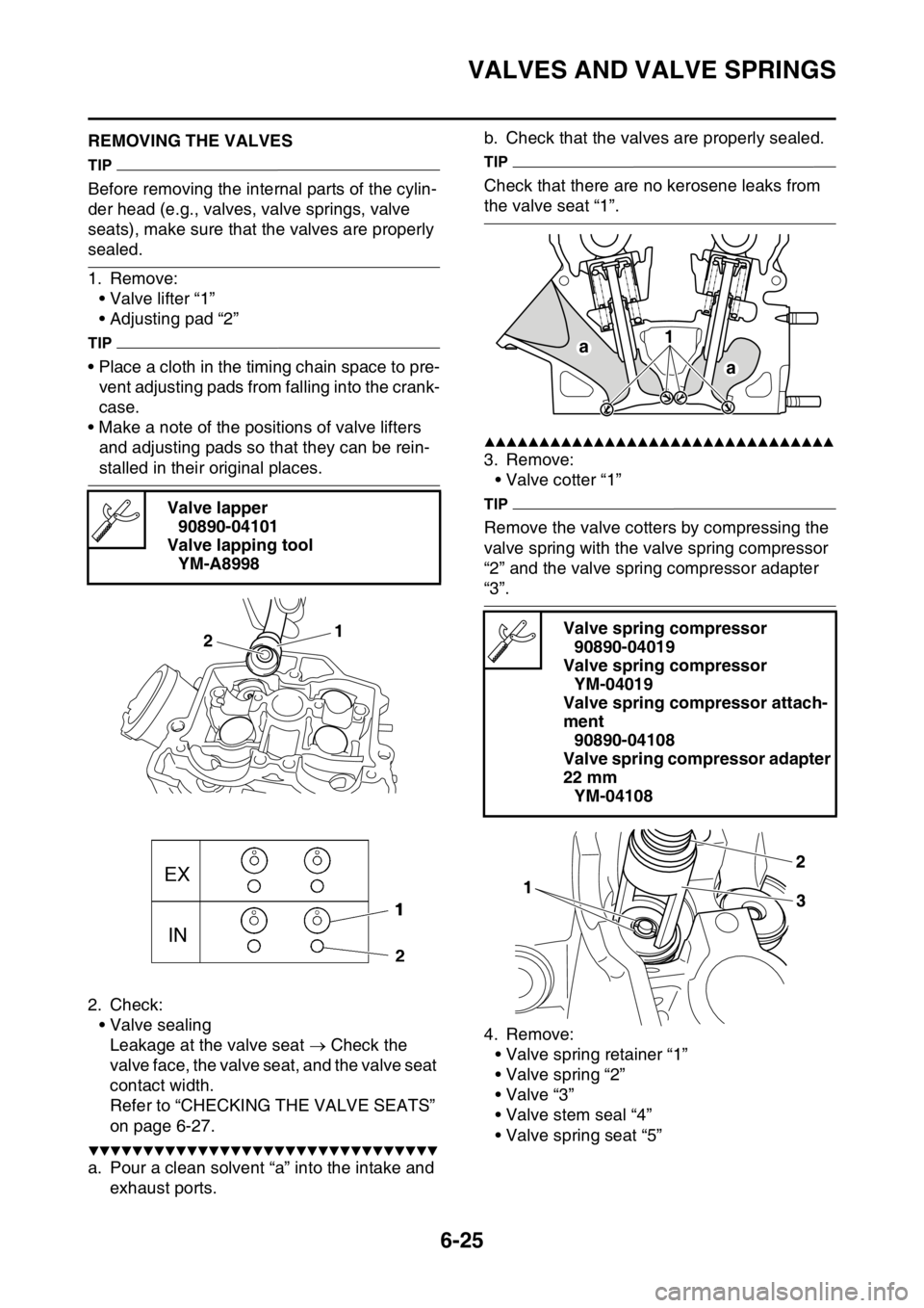
1. Remove:
• Valve lifter “1”
• Adjusting pad “2”
TIP
• Place a cloth in the timing chain space to pre-
vent adjusting pads from falling into the crank-
case.
• Make a note of the positions of valve lifters
and adjusting pads so that they can be rein-
stalled in their original places.
2. Check:
• Valve sealing
Leakage at the valve seat Check the
valve face, the valve seat, and the valve seat
contact width.
Refer to “CHECKING THE VALVE SEATS”
on page 6-27.
▼▼▼▼▼▼▼▼▼▼▼▼▼▼▼▼▼▼▼▼▼▼▼▼▼▼▼▼▼▼▼▼
a. Pour a clean solvent “a” into the intake and
exhaust ports.b. Check that the valves are properly sealed.
TIP
Check that there are no kerosene leaks from
the valve seat “1”.
▲▲▲▲▲▲▲▲▲▲▲▲▲▲▲▲▲▲▲▲▲▲▲▲▲▲▲▲▲▲▲▲
3. Remove:
• Valve cotter “1”
TIP
Remove the valve cotters by compressing the
valve spring with the valve spring compressor
“2” and the valve spring compressor adapter
“3”.
4. Remove:
• Valve spring retainer “1”
• Valve spring “2”
•Valve “3”
• Valve stem seal “4”
• Valve spring seat “5” Valve lapper
90890-04101
Valve lapping tool
YM-A8998
1
2Valve spring compressor
90890-04019
Valve spring compressor
YM-04019
Valve spring compressor attach-
ment
90890-04108
Valve spring compressor adapter
22 mm
YM-04108
a1
a
Page 256 of 432
VALVES AND VALVE SPRINGS
6-27
TIP
After replacing the valve guide, reface the valve
seat.
▲▲▲▲▲▲▲▲▲▲▲▲▲▲▲▲▲▲▲▲▲▲▲▲▲▲▲▲▲▲▲▲
3. Eliminate:
• Carbon deposits
(from the valve face and valve seat)
4. Check:
• Valve face
Pitting/wear Grind the valve face.
• Valve stem end
Mushroom shape or diameter larger than
the body of the valve stem Replace the
valve.
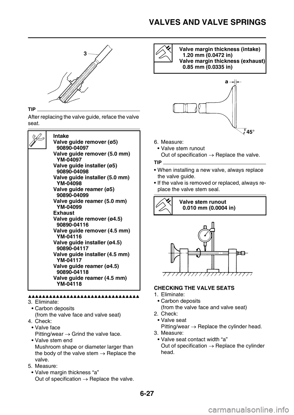
5. Measure:
• Valve margin thickness “a”
Out of specification Replace the valve.6. Measure:
• Valve stem runout
Out of specification Replace the valve.
TIP
• When installing a new valve, always replace
the valve guide.
• If the valve is removed or replaced, always re-
place the valve stem seal.
EAS2GBB252CHECKING THE VALVE SEATS
1. Eliminate:
• Carbon deposits
(from the valve face and valve seat)
2. Check:
• Valve seat
Pitting/wear Replace the cylinder head.
3. Measure:
• Valve seat contact width “a”
Out of specification Replace the cylinder
head. Intake
Valve guide remover (ø5)
90890-04097
Valve guide remover (5.0 mm)
YM-04097
Valve guide installer (ø5)
90890-04098
Valve guide installer (5.0 mm)
YM-04098
Valve guide reamer (ø5)
90890-04099
Valve guide reamer (5.0 mm)
YM-04099
Exhaust
Valve guide remover (ø4.5)
90890-04116
Valve guide remover (4.5 mm)
YM-04116
Valve guide installer (ø4.5)
90890-04117
Valve guide installer (4.5 mm)
YM-04117
Valve guide reamer (ø4.5)
90890-04118
Valve guide reamer (4.5 mm)
YM-04118
Valve margin thickness (intake)
1.20 mm (0.0472 in)
Valve margin thickness (exhaust)
0.85 mm (0.0335 in)
Valve stem runout
0.010 mm (0.0004 in)
Page 257 of 432
VALVES AND VALVE SPRINGS
6-28
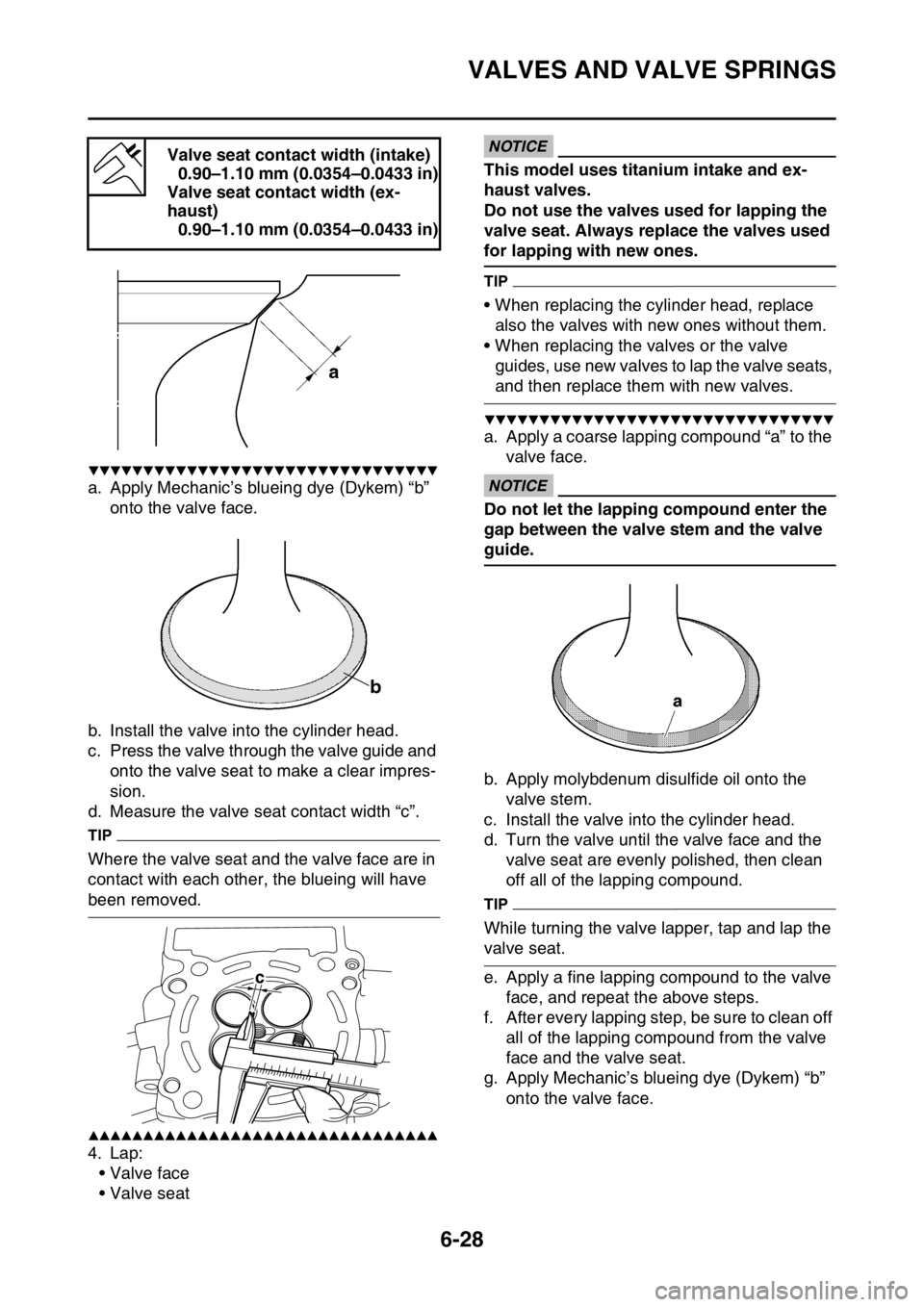
▼▼▼▼▼▼▼▼▼▼▼▼▼▼▼▼▼▼▼▼▼▼▼▼▼▼▼▼▼▼▼▼
a. Apply Mechanic’s blueing dye (Dykem) “b”
onto the valve face.
b. Install the valve into the cylinder head.
c. Press the valve through the valve guide and
onto the valve seat to make a clear impres-
sion.
d. Measure the valve seat contact width “c”.
TIP
Where the valve seat and the valve face are in
contact with each other, the blueing will have
been removed.
▲▲▲▲▲▲▲▲▲▲▲▲▲▲▲▲▲▲▲▲▲▲▲▲▲▲▲▲▲▲▲▲
4. Lap:
• Valve face
• Valve seat
ECA
NOTICE
This model uses titanium intake and ex-
haust valves.
Do not use the valves used for lapping the
valve seat. Always replace the valves used
for lapping with new ones.
TIP
• When replacing the cylinder head, replace
also the valves with new ones without them.
• When replacing the valves or the valve
guides, use new valves to lap the valve seats,
and then replace them with new valves.
▼▼▼▼▼▼▼▼▼▼▼▼▼▼▼▼▼▼▼▼▼▼▼▼▼▼▼▼▼▼▼▼
a. Apply a coarse lapping compound “a” to the
valve face.
ECA
NOTICE
Do not let the lapping compound enter the
gap between the valve stem and the valve
guide.
b. Apply molybdenum disulfide oil onto the
valve stem.
c. Install the valve into the cylinder head.
d. Turn the valve until the valve face and the
valve seat are evenly polished, then clean
off all of the lapping compound.
TIP
While turning the valve lapper, tap and lap the
valve seat.
e. Apply a fine lapping compound to the valve
face, and repeat the above steps.
f. After every lapping step, be sure to clean off
all of the lapping compound from the valve
face and the valve seat.
g. Apply Mechanic’s blueing dye (Dykem) “b”
onto the valve face. Valve seat contact width (intake)
0.90–1.10 mm (0.0354–0.0433 in)
Valve seat contact width (ex-
haust)
0.90–1.10 mm (0.0354–0.0433 in)
c
Page 258 of 432
VALVES AND VALVE SPRINGS
6-29
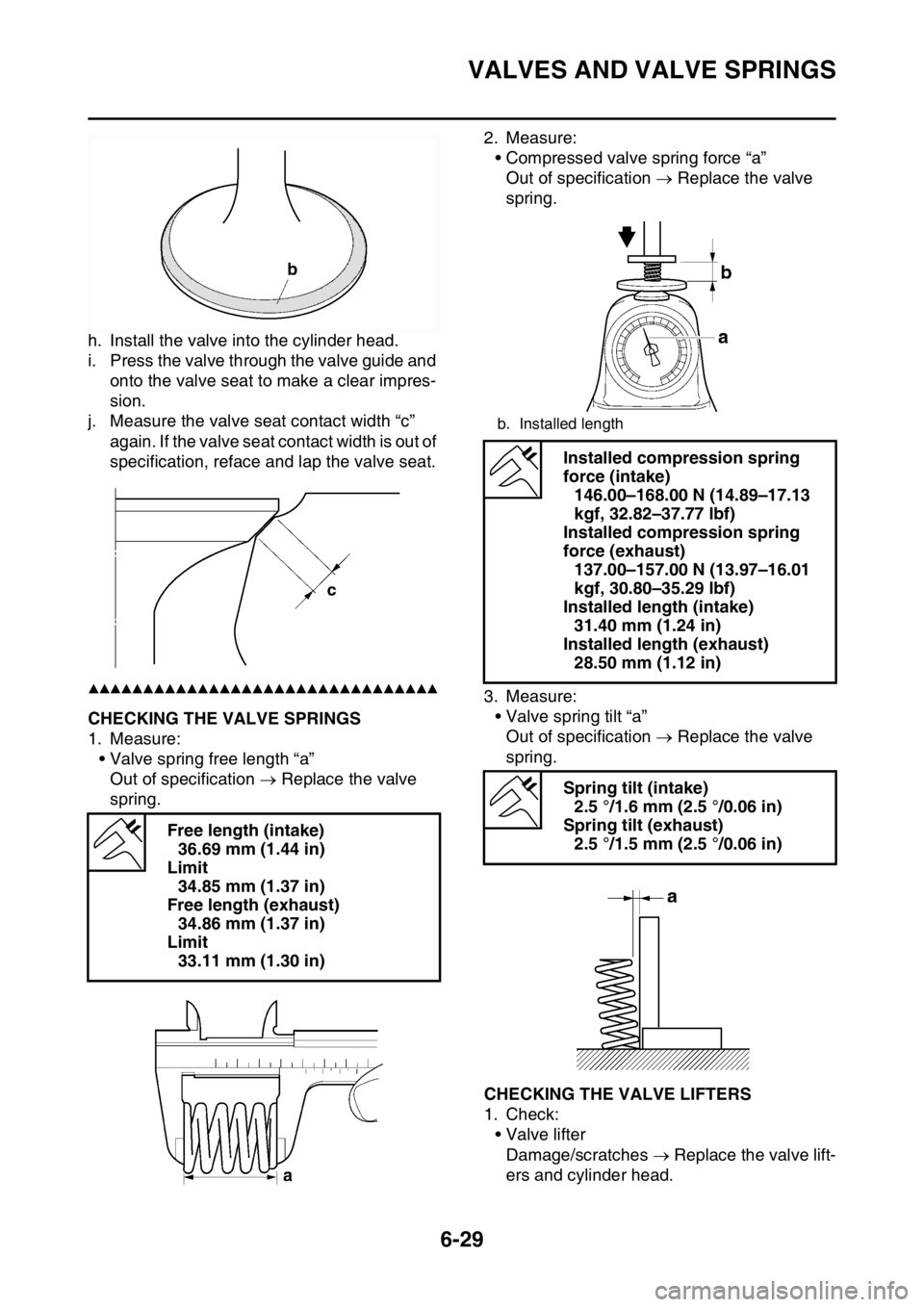
h. Install the valve into the cylinder head.
i. Press the valve through the valve guide and
onto the valve seat to make a clear impres-
sion.
j. Measure the valve seat contact width “c”
again. If the valve seat contact width is out of
specification, reface and lap the valve seat.
▲▲▲▲▲▲▲▲▲▲▲▲▲▲▲▲▲▲▲▲▲▲▲▲▲▲▲▲▲▲▲▲
EAS2GBB253CHECKING THE VALVE SPRINGS
1. Measure:
• Valve spring free length “a”
Out of specification Replace the valve
spring.2. Measure:
• Compressed valve spring force “a”
Out of specification Replace the valve
spring.
3. Measure:
• Valve spring tilt “a”
Out of specification Replace the valve
spring.
EAS2GBB254CHECKING THE VALVE LIFTERS
1. Check:
• Valve lifter
Damage/scratches Replace the valve lift-
ers and cylinder head. Free length (intake)
36.69 mm (1.44 in)
Limit
34.85 mm (1.37 in)
Free length (exhaust)
34.86 mm (1.37 in)
Limit
33.11 mm (1.30 in)
b. Installed length
Installed compression spring
force (intake)
146.00–168.00 N (14.89–17.13
kgf, 32.82–37.77 lbf)
Installed compression spring
force (exhaust)
137.00–157.00 N (13.97–16.01
kgf, 30.80–35.29 lbf)
Installed length (intake)
31.40 mm (1.24 in)
Installed length (exhaust)
28.50 mm (1.12 in)
Spring tilt (intake)
2.5 °/1.6 mm (2.5 °/0.06 in)
Spring tilt (exhaust)
2.5 °/1.5 mm (2.5 °/0.06 in)
Page 308 of 432
CRANKSHAFT ASSEMBLY AND BALANCER SHAFT
6-79
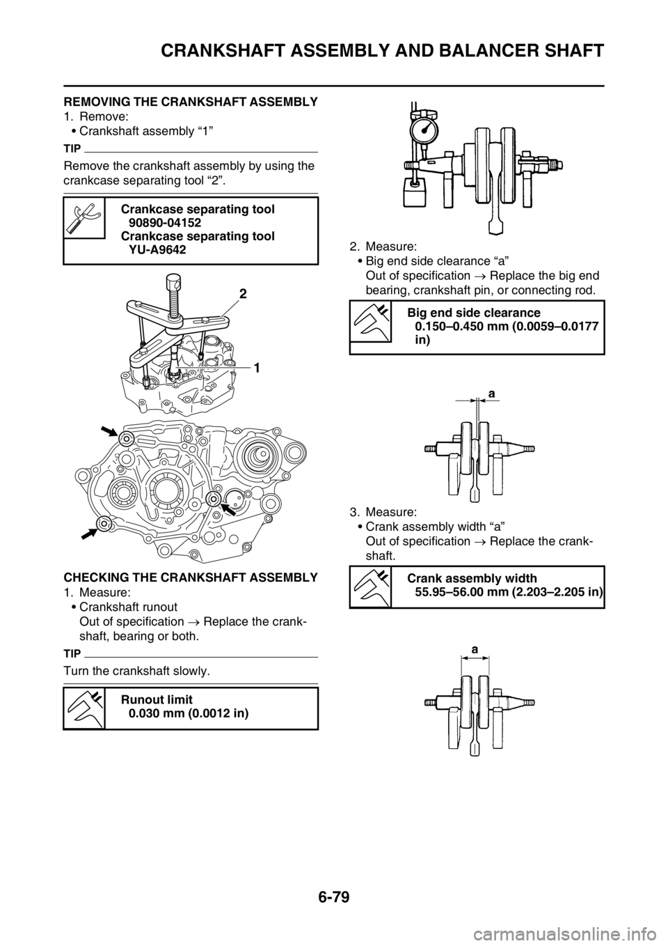
EAS2GBB318REMOVING THE CRANKSHAFT ASSEMBLY
1. Remove:
• Crankshaft assembly “1”
TIP
Remove the crankshaft assembly by using the
crankcase separating tool “2”.
EAS2GBB319CHECKING THE CRANKSHAFT ASSEMBLY
1. Measure:
• Crankshaft runout
Out of specification Replace the crank-
shaft, bearing or both.
TIP
Turn the crankshaft slowly.2. Measure:
• Big end side clearance “a”
Out of specification Replace the big end
bearing, crankshaft pin, or connecting rod.
3. Measure:
• Crank assembly width “a”
Out of specification Replace the crank-
shaft. Crankcase separating tool
90890-04152
Crankcase separating tool
YU-A9642
Runout limit
0.030 mm (0.0012 in)
2
1
Big end side clearance
0.150–0.450 mm (0.0059–0.0177
in)
Crank assembly width
55.95–56.00 mm (2.203–2.205 in)