wiring YAMAHA WR 250F 2017 Owners Manual
[x] Cancel search | Manufacturer: YAMAHA, Model Year: 2017, Model line: WR 250F, Model: YAMAHA WR 250F 2017Pages: 432, PDF Size: 14.14 MB
Page 341 of 432

IGNITION SYSTEM
9-5
8. Check the lean angle sensor.
Refer to “CHECKING THE LEAN
ANGLE SENSOR” on page 9-75.NG
Replace the lean angle sensor.
OK
9. Check the entire ignition system’s
wiring.
Refer to “CIRCUIT DIAGRAM” on
page 9-2.NG
Properly connect or repair the ignition sys-
tem’s wiring.
OK
Replace the ECU.
Page 347 of 432

ELECTRIC STARTING SYSTEM
9-11
8. Check the main relay.
Refer to “CHECKING THE RE-
LAYS” on page 9-72.NG
Replace the main relay.
OK
9. Check the neutral switch.
Refer to “CHECKING THE
SWITCHES” on page 9-64.NG
Replace the neutral switch.
OK
10.Check the clutch switch.
Refer to “CHECKING THE
SWITCHES” on page 9-64.NG
Replace the clutch switch.
OK
11.Check the engine stop switch.
Refer to “CHECKING THE
SWITCHES” on page 9-64.NG
Replace the engine stop switch.
OK
12.Check the start switch.
Refer to “CHECKING THE
SWITCHES” on page 9-64.NG
Replace the start switch.
OK
13.Check the entire starting system’s
wiring.
Refer to “CIRCUIT DIAGRAM” on
page 9-6.NG
Properly connect or repair the starting sys-
tem’s wiring.
OK
Replace the ECU.
Page 350 of 432
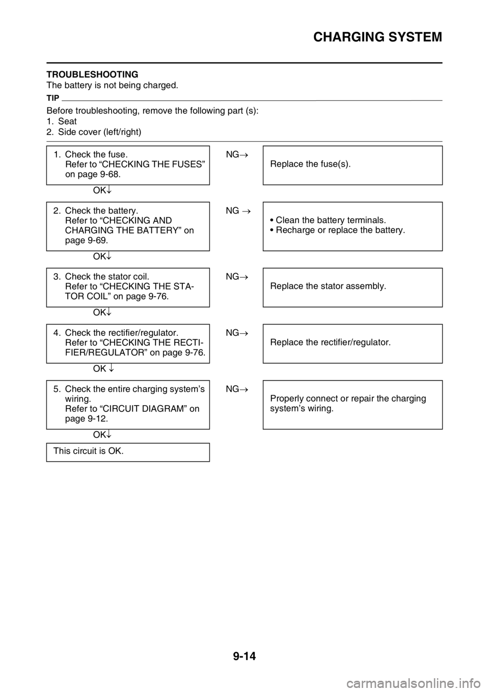
CHARGING SYSTEM
9-14
EAS2GBB364TROUBLESHOOTING
The battery is not being charged.
TIP
Before troubleshooting, remove the following part (s):
1. Seat
2. Side cover (left/right)
1. Check the fuse.
Refer to “CHECKING THE FUSES”
on page 9-68.NG
Replace the fuse(s).
OK
2. Check the battery.
Refer to “CHECKING AND
CHARGING THE BATTERY” on
page 9-69.NG
• Clean the battery terminals.
• Recharge or replace the battery.
OK
3. Check the stator coil.
Refer to “CHECKING THE STA-
TOR COIL” on page 9-76.NG
Replace the stator assembly.
OK
4. Check the rectifier/regulator.
Refer to “CHECKING THE RECTI-
FIER/REGULATOR” on page 9-76.NG
Replace the rectifier/regulator.
OK
5. Check the entire charging system’s
wiring.
Refer to “CIRCUIT DIAGRAM” on
page 9-12.NG
Properly connect or repair the charging
system’s wiring.
OK
This circuit is OK.
Page 354 of 432
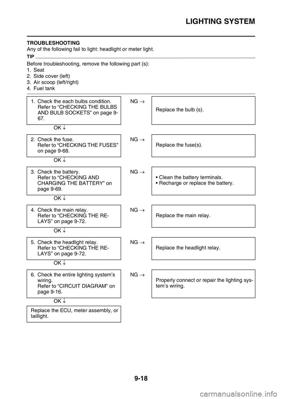
LIGHTING SYSTEM
9-18
EAS2GBB366TROUBLESHOOTING
Any of the following fail to light: headlight or meter light.
TIP
Before troubleshooting, remove the following part (s):
1. Seat
2. Side cover (left)
3. Air scoop (left/right)
4. Fuel tank
1. Check the each bulbs condition.
Refer to “CHECKING THE BULBS
AND BULB SOCKETS” on page 9-
67.NG
Replace the bulb (s).
OK
2. Check the fuse.
Refer to “CHECKING THE FUSES”
on page 9-68.NG
Replace the fuse(s).
OK
3. Check the battery.
Refer to “CHECKING AND
CHARGING THE BATTERY” on
page 9-69.NG
• Clean the battery terminals.
• Recharge or replace the battery.
OK
4. Check the main relay.
Refer to “CHECKING THE RE-
LAYS” on page 9-72.NG
Replace the main relay.
OK
5. Check the headlight relay.
Refer to “CHECKING THE RE-
LAYS” on page 9-72.NG
Replace the headlight relay.
OK
6. Check the entire lighting system’s
wiring.
Refer to “CIRCUIT DIAGRAM” on
page 9-16.NG
Properly connect or repair the lighting sys-
tem’s wiring.
OK
Replace the ECU, meter assembly, or
taillight.
Page 358 of 432

SIGNALING SYSTEM
9-22
EAS2GBB368TROUBLESHOOTING
• The speedometer does not operate normally.
• The fuel indicator light does not come on.
TIP
Before troubleshooting, remove the following part (s):
1. Seat
2. Side cover (left/right)
3. Air scoop (left/right)
4. Fuel tank
Check the signaling system
The speedometer fails to operate.
1. Check the fuse.
Refer to “CHECKING THE FUSES”
on page 9-68.NG
Replace the fuse(s).
OK
2. Check the battery.
Refer to “CHECKING AND
CHARGING THE BATTERY” on
page 9-69.NG
• Clean the battery terminals.
• Recharge or replace the battery.
OK
3. Check the main relay.
Refer to “CHECKING THE RE-
LAYS” on page 9-72.NG
Replace the main relay.
OK
4. Check the entire signaling system’s
wiring.
Refer to “CIRCUIT DIAGRAM” on
page 9-20.NG
Properly connect or repair the signaling
system’s wiring.
OK
This circuit is OK.
1. Check the speed sensor.
Refer to “CHECKING THE SPEED
SENSOR” on page 9-77.NG
Replace the speed sensor.
OK
2. Check the entire signaling system’s
wiring.
Refer to “CIRCUIT DIAGRAM” on
page 9-20.NG
Properly connect or repair the signaling
system’s wiring.
OK
Replace the meter assembly.
Page 359 of 432

SIGNALING SYSTEM
9-23
The fuel level warning light fails to come on.
1. Check the fuel sender.
Refer to “CHECKING THE FUEL
SENDER” on page 9-77.NG
Replace the fuel sender assembly.
OK
2. Check the resistor.
Refer to “CHECKING THE RESIST-
ER” on page 9-78.NG
Replace the resistor.
OK
3. Check the entire signaling system’s
wiring.
Refer to “CIRCUIT DIAGRAM” on
page 9-20.NG
Properly connect or repair the signaling
system’s wiring.
OK
Replace the indicator light assembly.
Page 362 of 432
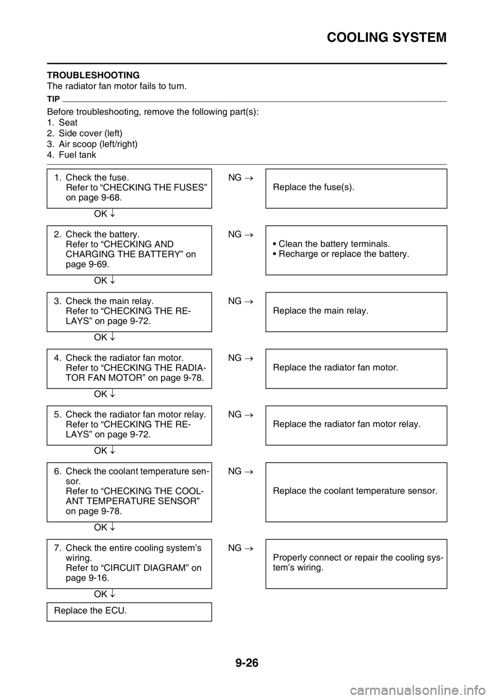
COOLING SYSTEM
9-26
EAS2GBB371TROUBLESHOOTING
The radiator fan motor fails to turn.
TIP
Before troubleshooting, remove the following part(s):
1. Seat
2. Side cover (left)
3. Air scoop (left/right)
4. Fuel tank
1. Check the fuse.
Refer to “CHECKING THE FUSES”
on page 9-68.NG
Replace the fuse(s).
OK
2. Check the battery.
Refer to “CHECKING AND
CHARGING THE BATTERY” on
page 9-69.NG
• Clean the battery terminals.
• Recharge or replace the battery.
OK
3. Check the main relay.
Refer to “CHECKING THE RE-
LAYS” on page 9-72.NG
Replace the main relay.
OK
4. Check the radiator fan motor.
Refer to “CHECKING THE RADIA-
TOR FAN MOTOR” on page 9-78.NG
Replace the radiator fan motor.
OK
5. Check the radiator fan motor relay.
Refer to “CHECKING THE RE-
LAYS” on page 9-72.NG
Replace the radiator fan motor relay.
OK
6. Check the coolant temperature sen-
sor.
Refer to “CHECKING THE COOL-
ANT TEMPERATURE SENSOR”
on page 9-78.NG
Replace the coolant temperature sensor.
OK
7. Check the entire cooling system’s
wiring.
Refer to “CIRCUIT DIAGRAM” on
page 9-16.NG
Properly connect or repair the cooling sys-
tem’s wiring.
OK
Replace the ECU.
Page 394 of 432
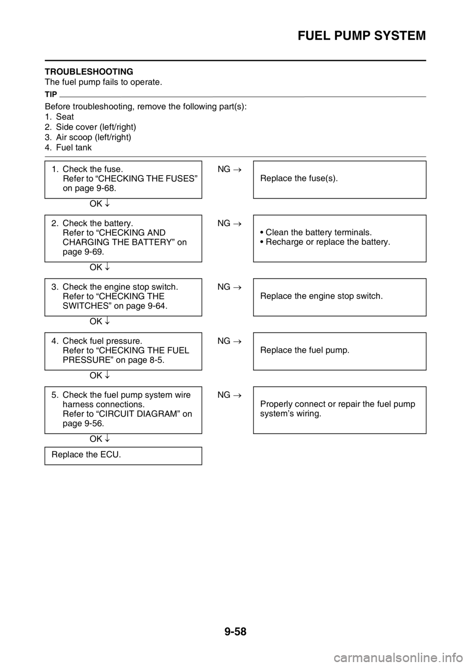
FUEL PUMP SYSTEM
9-58
EAS2GBB380TROUBLESHOOTING
The fuel pump fails to operate.
TIP
Before troubleshooting, remove the following part(s):
1. Seat
2. Side cover (left/right)
3. Air scoop (left/right)
4. Fuel tank
1. Check the fuse.
Refer to “CHECKING THE FUSES”
on page 9-68.NG
Replace the fuse(s).
OK
2. Check the battery.
Refer to “CHECKING AND
CHARGING THE BATTERY” on
page 9-69.NG
• Clean the battery terminals.
• Recharge or replace the battery.
OK
3. Check the engine stop switch.
Refer to “CHECKING THE
SWITCHES” on page 9-64.NG
Replace the engine stop switch.
OK
4. Check fuel pressure.
Refer to “CHECKING THE FUEL
PRESSURE” on page 8-5.NG
Replace the fuel pump.
OK
5. Check the fuel pump system wire
harness connections.
Refer to “CIRCUIT DIAGRAM” on
page 9-56.NG
Properly connect or repair the fuel pump
system’s wiring.
OK
Replace the ECU.
Page 402 of 432
ELECTRICAL COMPONENTS
9-66
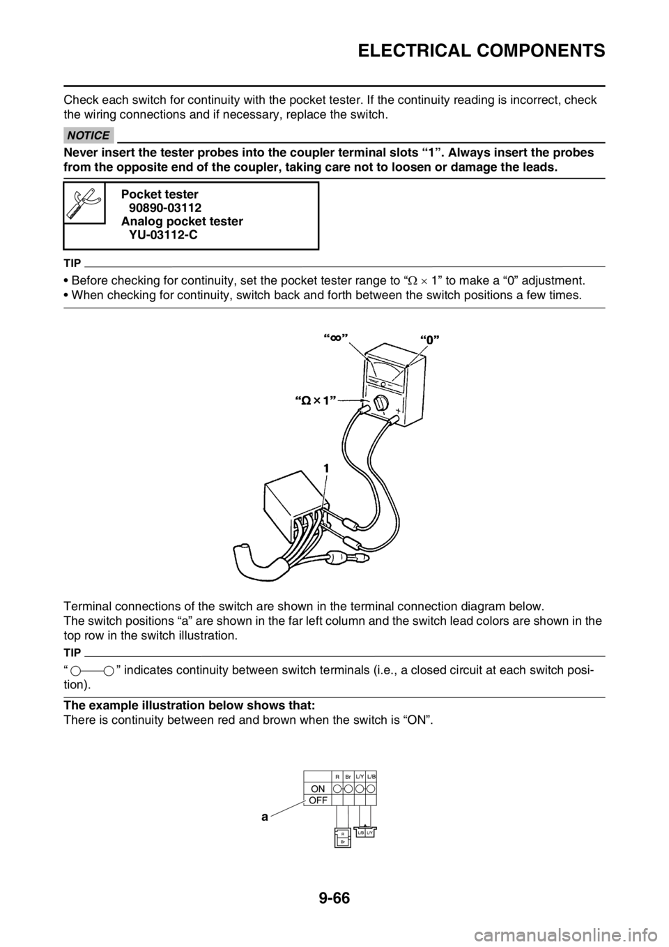
Check each switch for continuity with the pocket tester. If the continuity reading is incorrect, check
the wiring connections and if necessary, replace the switch.
ECA
NOTICE
Never insert the tester probes into the coupler terminal slots “1”. Always insert the probes
from the opposite end of the coupler, taking care not to loosen or damage the leads.
TIP
• Before checking for continuity, set the pocket tester range to “ 1” to make a “0” adjustment.
• When checking for continuity, switch back and forth between the switch positions a few times.
Terminal connections of the switch are shown in the terminal connection diagram below.
The switch positions “a” are shown in the far left column and the switch lead colors are shown in the
top row in the switch illustration.
TIP
“ ” indicates continuity between switch terminals (i.e., a closed circuit at each switch posi-
tion).
The example illustration below shows that:
There is continuity between red and brown when the switch is “ON”.Pocket tester
90890-03112
Analog pocket tester
YU-03112-C
a
Page 420 of 432
TROUBLESHOOTING
10-1
EAS2GBB405
TROUBLESHOOTING
EAS2GBB406GENERAL INFORMATION
TIP
The following guide for troubleshooting does
not cover all the possible causes of trouble. It
should be helpful, however, as a guide to basic
troubleshooting. Refer to the relative procedure
in this manual for checks, adjustments, and re-
placement of parts.
EAS2GBB407STARTING FAILURES
Engine
1. Cylinder and cylinder head
• Loose spark plug
• Loose cylinder head or cylinder
• Damaged cylinder head gasket
• Damaged cylinder gasket
• Worn or damaged cylinder
• Incorrect valve clearance
• Improperly sealed valve
• Incorrect valve-to-valve-seat contact
• Incorrect valve timing
• Faulty valve spring
• Seized valve
2. Piston and piston ring(s)
• Improperly installed piston ring
• Damaged, worn or fatigued piston ring
• Seized piston ring
• Seized or damaged piston
3. Air filter
• Improperly installed air filter
• Clogged air filter element
4. Crankcase and crankshaft
• Improperly assembled crankcase
• Seized crankshaft
Fuel system
1. Fuel tank
• Empty fuel tank
• Clogged fuel tank breather hose
• Deteriorated or contaminated fuel
• Clogged or damaged fuel hose
2. Fuel pump
• Faulty fuel pump
3. Throttle body
• Deteriorated or contaminated fuel
• Sucked-in airElectrical system
1. Battery
• Discharged battery
• Faulty battery
2. Fuse
• Blown, damaged or incorrect fuse
• Improperly installed fuse
3. Spark plug
• Incorrect spark plug gap
• Incorrect spark plug heat range
• Fouled spark plug
• Worn or damaged electrode
• Worn or damaged insulator
4. Ignition coil
• Cracked or broken ignition coil body
• Broken or shorted primary or secondary
coils
5. Ignition system
• Faulty ECU
• Faulty crankshaft position sensor
• Broken generator rotor woodruff key
6. Switches and wiring
• Faulty ECU
• Faulty engine stop switch
• Broken or shorted wiring
• Faulty neutral switch
• Improperly grounded circuit
• Loose connections
7. Starting system
• Faulty starter motor
• Faulty starter relay
• Faulty starting circuit cut-off relay
• Faulty starter clutch
EAS2GBB408INCORRECT ENGINE IDLING SPEED
Engine
1. Cylinder and cylinder head
• Incorrect valve clearance
• Damaged valve train components
2. Air filter
• Clogged air filter element
Fuel system
1. Throttle body
• Damaged or loose throttle body joint
• Improperly synchronized throttle bodies
• Improper throttle cable free play
• Flooded throttle body