check engine YAMAHA WR 250R 2011 Owner's Manual
[x] Cancel search | Manufacturer: YAMAHA, Model Year: 2011, Model line: WR 250R, Model: YAMAHA WR 250R 2011Pages: 98, PDF Size: 2.57 MB
Page 58 of 98
PERIODIC MAINTENANCE AND ADJUSTMENT
6-16
1
2
3
4
56
7
8
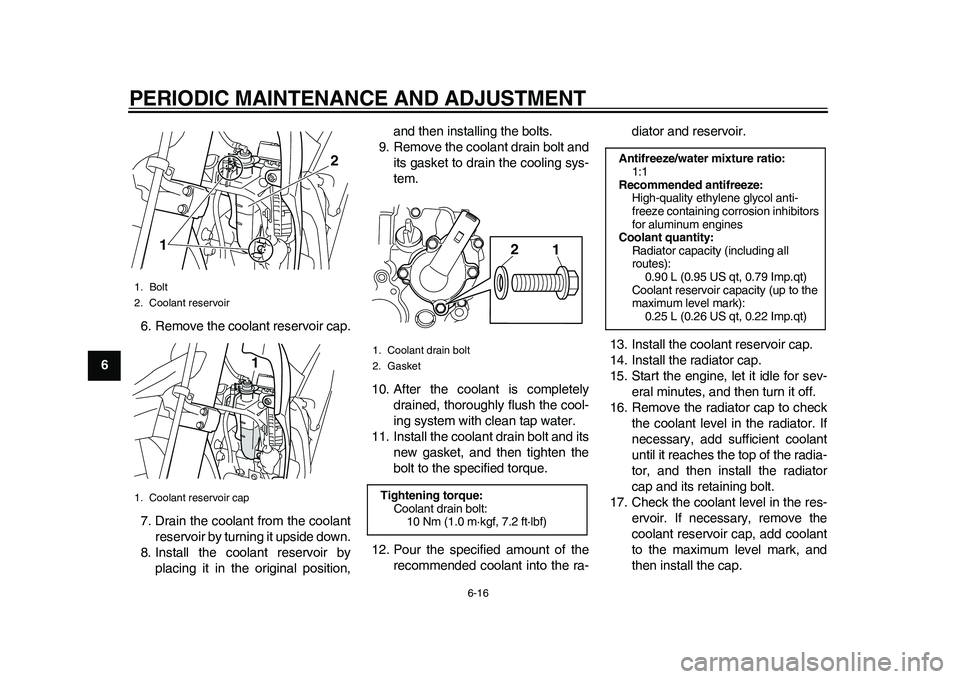
96. Remove the coolant reservoir cap.
7. Drain the coolant from the coolant
reservoir by turning it upside down.
8. Install the coolant reservoir by
placing it in the original position,and then installing the bolts.
9. Remove the coolant drain bolt and
its gasket to drain the cooling sys-
tem.
10. After the coolant is completely
drained, thoroughly flush the cool-
ing system with clean tap water.
11. Install the coolant drain bolt and its
new gasket, and then tighten the
bolt to the specified torque.
12. Pour the specified amount of the
recommended coolant into the ra-diator and reservoir.
13. Install the coolant reservoir cap.
14. Install the radiator cap.
15. Start the engine, let it idle for sev-
eral minutes, and then turn it off.
16. Remove the radiator cap to check
the coolant level in the radiator. If
necessary, add sufficient coolant
until it reaches the top of the radia-
tor, and then install the radiator
cap and its retaining bolt.
17. Check the coolant level in the res-
ervoir. If necessary, remove the
coolant reservoir cap, add coolant
to the maximum level mark, and
then install the cap.
1. Bolt
2. Coolant reservoir
1. Coolant reservoir cap
12
1
1. Coolant drain bolt
2. GasketTightening torque:
Coolant drain bolt:
10 Nm (1.0 m·kgf, 7.2 ft·lbf)
1 2
Antifreeze/water mixture ratio:
1:1
Recommended antifreeze:
High-quality ethylene glycol anti-
freeze containing corrosion inhibitors
for aluminum engines
Coolant quantity:
Radiator capacity (including all
routes):
0.90 L (0.95 US qt, 0.79 Imp.qt)
Coolant reservoir capacity (up to the
maximum level mark):
0.25 L (0.26 US qt, 0.22 Imp.qt)
32D-9-E6.book 16 ページ 2011年1月7日 金曜日 午後3時10分
Page 59 of 98
PERIODIC MAINTENANCE AND ADJUSTMENT
6-17
2
3
4
567
8
9 18. Start the engine, and then check
the vehicle for coolant leakage. If
coolant is leaking, have a Yamaha
dealer check the cooling system.
19. Install the panels.
EAU44323
Cleaning the air filter element
and check hose The air filter element should be cleaned
or replaced at the intervals specified in
the periodic maintenance and lubrica-
tion chart. Clean or, if necessary, re-
place the air filter element more
frequently if you are riding in unusually
wet or dusty areas. In addition, the air
filter check hose must be frequently
checked and cleaned if necessary.
To clean the air filter element
1. Remove panel B. (See page 6-8.)
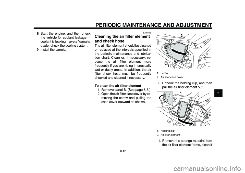
2. Open the air filter case cover by re-
moving the screw and pulling the
case cover outward as shown.3. Unhook the holding clip, and then
pull the air filter element out.
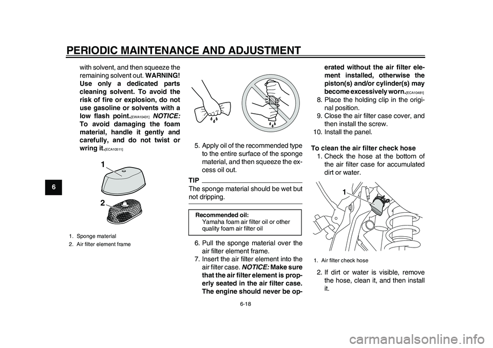
4. Remove the sponge material from
the air filter element frame, clean it
1. Screw
2. Air filter case cover
1. Holding clip
2. Air filter element
2
11
2
32D-9-E6.book 17 ページ 2011年1月7日 金曜日 午後3時10分
Page 60 of 98
PERIODIC MAINTENANCE AND ADJUSTMENT
6-18
1
2
3
4
56
7
8
9with solvent, and then squeeze the
remaining solvent out. WARNING!
Use only a dedicated parts
cleaning solvent. To avoid the
risk of fire or explosion, do not
use gasoline or solvents with a
low flash point.
[EWA10431]
NOTICE:
To avoid damaging the foam
material, handle it gently and
carefully, and do not twist or
wring it.
[ECA10511]
5. Apply oil of the recommended type
to the entire surface of the sponge
material, and then squeeze the ex-
cess oil out.
TIPThe sponge material should be wet butnot dripping.
6. Pull the sponge material over the
air filter element frame.
7. Insert the air filter element into the
air filter case. NOTICE: Make sure
that the air filter element is prop-
erly seated in the air filter case.
The engine should never be op-erated without the air filter ele-
ment installed, otherwise the
piston(s) and/or cylinder(s) may
become excessively worn.
[ECA10481]
8. Place the holding clip in the origi-
nal position.
9. Close the air filter case cover, and
then install the screw.
10. Install the panel.
To clean the air filter check hose
1. Check the hose at the bottom of
the air filter case for accumulated
dirt or water.
2. If dirt or water is visible, remove
the hose, clean it, and then install
it.
1. Sponge material
2. Air filter element frame
1
2
Recommended oil:
Yamaha foam air filter oil or other
quality foam air filter oil
1. Air filter check hose
1
32D-9-E6.book 18 ページ 2011年1月7日 金曜日 午後3時10分
Page 61 of 98
PERIODIC MAINTENANCE AND ADJUSTMENT
6-19
2
3
4
567
8
9
EAU45322
Adjusting the engine idling
speed The engine idling speed must be
checked and, if necessary, adjusted as
follows.TIPA digital tachometer is needed to makethis adjustment.
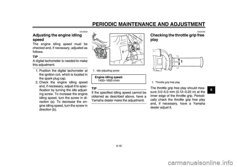
1. Position the digital tachometer at
the ignition coil, which is located in
the spark plug cap.
2. Check the engine idling speed
and, if necessary, adjust it to spec-
ification by turning the idle adjust-
ing screw. To increase the engine
idling speed, turn the screw in di-
rection (a). To decrease the en-
gine idling speed, turn the screw in
direction (b).
TIPIf the specified idling speed cannot be
obtained as described above, have aYamaha dealer make the adjustment.
EAU21384
Checking the throttle grip free
play The throttle grip free play should mea-
sure 3.0–5.0 mm (0.12–0.20 in) at the
inner edge of the throttle grip. Periodi-
cally check the throttle grip free play
and, if necessary, have a Yamaha
dealer adjust it.
1. Idle adjusting screwEngine idling speed:
1450–1650 r/min
1
(b)
(a)
1. Throttle grip free play
1
32D-9-E6.book 19 ページ 2011年1月7日 金曜日 午後3時10分
Page 62 of 98
PERIODIC MAINTENANCE AND ADJUSTMENT
6-20
1
2
3
4
56
7
8
9
EAU21401
Valve clearance The valve clearance changes with use,
resulting in improper air-fuel mixture
and/or engine noise. To prevent this
from occurring, the valve clearance
must be adjusted by a Yamaha dealer
at the intervals specified in the periodic
maintenance and lubrication chart.
EAU21643
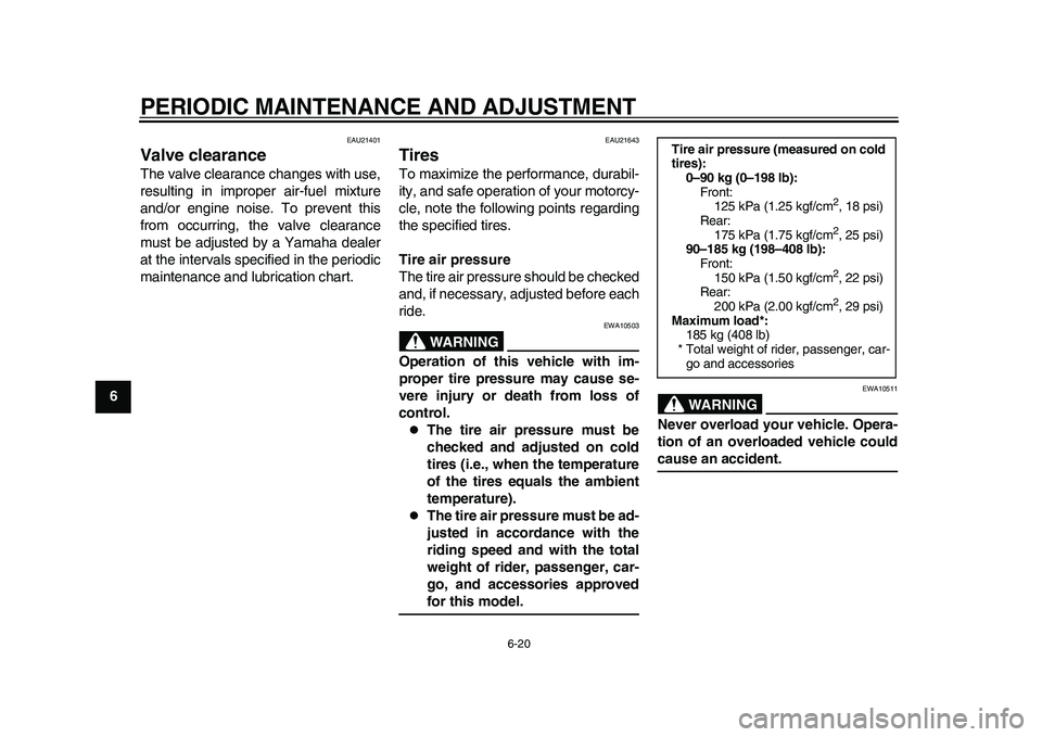
Tires To maximize the performance, durabil-
ity, and safe operation of your motorcy-
cle, note the following points regarding
the specified tires.
Tire air pressure
The tire air pressure should be checked
and, if necessary, adjusted before each
ride.
WARNING
EWA10503
Operation of this vehicle with im-
proper tire pressure may cause se-
vere injury or death from loss of
control.
The tire air pressure must be
checked and adjusted on cold
tires (i.e., when the temperature
of the tires equals the ambient
temperature).
The tire air pressure must be ad-
justed in accordance with the
riding speed and with the total
weight of rider, passenger, car-
go, and accessories approvedfor this model.
WARNING
EWA10511
Never overload your vehicle. Opera-
tion of an overloaded vehicle couldcause an accident.Tire air pressure (measured on cold
tires):
0–90 kg (0–198 lb):
Front:
125 kPa (1.25 kgf/cm
2, 18 psi)
Rear:
175 kPa (1.75 kgf/cm2, 25 psi)
90–185 kg (198–408 lb):
Front:
150 kPa (1.50 kgf/cm2, 22 psi)
Rear:
200 kPa (2.00 kgf/cm2, 29 psi)
Maximum load*:
185 kg (408 lb)
* Total weight of rider, passenger, car-
go and accessories
32D-9-E6.book 20 ページ 2011年1月7日 金曜日 午後3時10分
Page 71 of 98
PERIODIC MAINTENANCE AND ADJUSTMENT
6-29
2
3
4
567
8
9
EAU23095
Checking and lubricating the
cables The operation of all control cables and
the condition of the cables should be
checked before each ride, and the ca-
bles and cable ends should be lubricat-
ed if necessary. If a cable is damaged
or does not move smoothly, have a
Yamaha dealer check or replace it.
WARNING! Damage to the outer
housing of cables may result in in-
ternal rusting and cause interfer-
ence with cable movement. Replace
damaged cables as soon as possi-
ble to prevent unsafe condi-
tions.
[EWA10711]
EAU23114
Checking and lubricating the
throttle grip and cable The operation of the throttle grip should
be checked before each ride. In addi-
tion, the cable should be lubricated by a
Yamaha dealer at the intervals speci-
fied in the periodic maintenance chart.
The throttle cable is equipped with a
rubber cover. Make sure that the cover
is securely installed. Even though the
cover is installed correctly, it does not
completely protect the cable from water
entry. Therefore, use care not to pour
water directly onto the cover or cable
when washing the vehicle. If the cable
or cover becomes dirty, wipe clean with
a moist cloth.
EAU23142
Checking and lubricating the
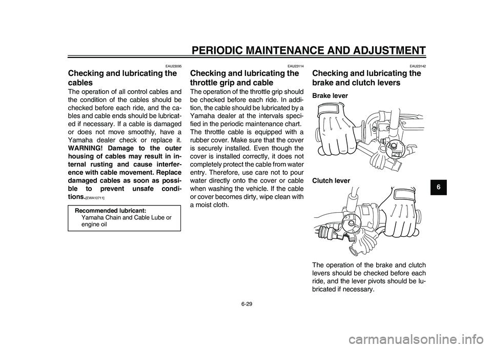
brake and clutch levers Brake lever
Clutch lever
The operation of the brake and clutch
levers should be checked before each
ride, and the lever pivots should be lu-
bricated if necessary.
Recommended lubricant:
Yamaha Chain and Cable Lube or
engine oil
32D-9-E6.book 29 ページ 2011年1月7日 金曜日 午後3時10分
Page 74 of 98
PERIODIC MAINTENANCE AND ADJUSTMENT
6-32
1
2
3
4
56
7
8
9
EAU23283
Checking the steering Worn or loose steering bearings may
cause danger. Therefore, the operation
of the steering must be checked as fol-
lows at the intervals specified in the pe-
riodic maintenance and lubrication
chart.
1. Place a stand under the engine to
raise the front wheel off the
ground. (See page 6-38 for more
information.) WARNING! To
avoid injury, securely support
the vehicle so there is no danger
of it falling over.
[EWA10751]
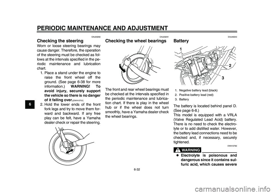
2. Hold the lower ends of the front
fork legs and try to move them for-
ward and backward. If any free
play can be felt, have a Yamaha
dealer check or repair the steering.
EAU23291
Checking the wheel bearings The front and rear wheel bearings must
be checked at the intervals specified in
the periodic maintenance and lubrica-
tion chart. If there is play in the wheel
hub or if the wheel does not turn
smoothly, have a Yamaha dealer check
the wheel bearings.
EAU46343
Battery The battery is located behind panel D.
(See page 6-8.)
This model is equipped with a VRLA
(Valve Regulated Lead Acid) battery.
There is no need to check the electro-
lyte or to add distilled water. However,
the battery lead connections need to be
checked and, if necessary, securely
tightened.
WARNING
EWA10760
Electrolyte is poisonous and
dangerous since it contains sul-
furic acid, which causes severe
1. Negative battery lead (black)
2. Positive battery lead (red)
3. Battery
3
2
1
32D-9-E6.book 32 ページ 2011年1月7日 金曜日 午後3時10分
Page 80 of 98
PERIODIC MAINTENANCE AND ADJUSTMENT
6-38
1
2
3
4
56
7
8
9
EAU45222
Replacing an auxiliary light
bulb If the auxiliary light bulb burns out, re-
place it as follows.
1. Remove the headlight unit. (See
page 6-35.)
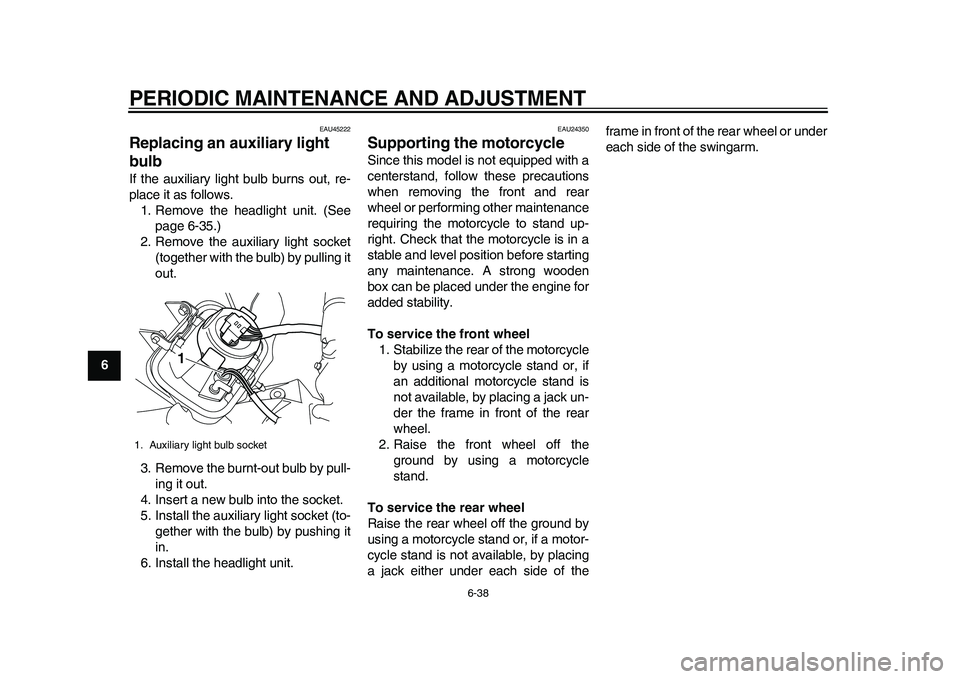
2. Remove the auxiliary light socket
(together with the bulb) by pulling it
out.
3. Remove the burnt-out bulb by pull-
ing it out.
4. Insert a new bulb into the socket.
5. Install the auxiliary light socket (to-
gether with the bulb) by pushing it
in.
6. Install the headlight unit.
EAU24350
Supporting the motorcycle Since this model is not equipped with a
centerstand, follow these precautions
when removing the front and rear
wheel or performing other maintenance
requiring the motorcycle to stand up-
right. Check that the motorcycle is in a
stable and level position before starting
any maintenance. A strong wooden
box can be placed under the engine for
added stability.
To service the front wheel
1. Stabilize the rear of the motorcycle
by using a motorcycle stand or, if
an additional motorcycle stand is
not available, by placing a jack un-
der the frame in front of the rear
wheel.
2. Raise the front wheel off the
ground by using a motorcycle
stand.
To service the rear wheel
Raise the rear wheel off the ground by
using a motorcycle stand or, if a motor-
cycle stand is not available, by placing
a jack either under each side of theframe in front of the rear wheel or under
each side of the swingarm.
1. Auxiliary light bulb socket
1
32D-9-E6.book 38 ページ 2011年1月7日 金曜日 午後3時10分
Page 85 of 98
PERIODIC MAINTENANCE AND ADJUSTMENT
6-43
2
3
4
567
8
9
EAU42133
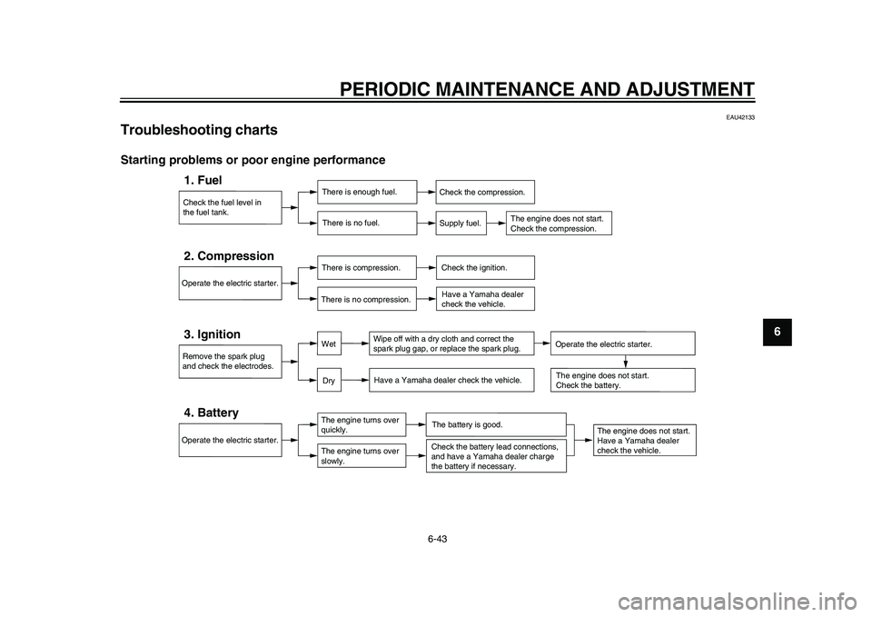
Troubleshooting charts Starting problems or poor engine performance
Check the fuel level in
the fuel tank.1. Fuel
There is enough fuel.
There is no fuel.
Check the compression.
Supply fuel.
The engine does not start.
Check the compression.
Operate the electric starter.2. Compression
There is compression.
There is no compression.
Check the ignition.
Have a Yamaha dealer
check the vehicle.
Remove the spark plug
and check the electrodes.3. Ignition
Wipe off with a dry cloth and correct the
spark plug gap, or replace the spark plug.
Have a Yamaha dealer check the vehicle.
The engine does not start.
Have a Yamaha dealer
check the vehicle.
The engine does not start.
Check the battery.
Operate the electric starter.4. Battery
The engine turns over
quickly.
The engine turns over
slowly.
The battery is good.
DryWet
Operate the electric starter.
Check the battery lead connections,
and have a Yamaha dealer charge
the battery if necessary.
32D-9-E6.book 43 ページ 2011年1月7日 金曜日 午後3時10分
Page 86 of 98
PERIODIC MAINTENANCE AND ADJUSTMENT
6-44
1
2
3
4
56
7
8
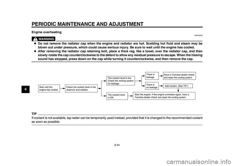
9Engine overheating
WARNING
EWA10400
Do not remove the radiator cap when the engine and radiator are hot. Scalding hot fluid and steam may be
blown out under pressure, which could cause serious injury. Be sure to wait until the engine has cooled.
After removing the radiator cap retaining bolt, place a thick rag, like a towel, over the radiator cap, and then
slowly rotate the cap counterclockwise to the detent to allow any residual pressure to escape. When the hissingsound has stopped, press down on the cap while turning it counterclockwise, and then remove the cap.
TIPIf coolant is not available, tap water can be temporarily used instead, provided that it is changed to the recommended coolantas soon as possible.
Wait until the
engine has cooled.
Check the coolant level in the
reservoir and radiator.
The coolant level
is OK.The coolant level is low.
Check the cooling system
for leakage.
Have a Yamaha dealer checkand repair the cooling system.Add coolant. (See TIP.)
Start the engine. If the engine overheats again,
have a
Yamaha dealer check
and repair the cooling system.
There is
leakage.
There is
no leakage.
32D-9-E6.book 44 ページ 2011年1月7日 金曜日 午後3時10分